Polar Capacitors: Types,Polarity Guide,Testing & Applications
What Are Polar Capacitors?
Polar capacitors are electrochemical energy storage components characterized by clear positive (anode) and negative (cathode) terminals. Their operation depends on strict polarity alignment with the circuit; incorrect wiring disrupts internal electrochemical balance, leading to failure. In contrast, non-polar capacitors (e.g., mica capacitors, Paper Capacitors, film capacitors) have no polarity restrictions. They can be connected in any direction, each tailored to specific high-frequency, high-voltage, or low-loss scenarios. You can also read our related article, What's the capacitor polarity
How Polar Capacitors Work
Polar capacitors operate based on electrochemical reactions, while non-polar types rely on physical polarization—both leveraging a dielectric layer to separate charge:
• Polar capacitors: When connected to Direct Current (DC), metal atoms on the anode (typically made of valve metals like aluminum or tantalum) lose electrons, forming a positive charge layer. The electrolyte generates negative charges through ion movement, interacting with the cathode to form a negative charge layer. A thin dielectric oxide layer (e.g., aluminum oxide for aluminum electrolytic capacitors, tantalum oxide for tantalum types) forms on the anode surface, acting as the charge-separating medium.
• Non-polar capacitors (e.g., Mica Capacitors): Store energy via electrostatic polarization of the dielectric (mica sheets). Mica’s high dielectric strength and low dissipation factor (DF, a measure of energy loss) make it ideal for high-frequency circuits like RF broadcast transmitters or resonance circuits.
Structure & Dielectric
The basic structure consists of two polar electrodes, an intermediate dielectric, and an electrolyte. Electrodes are typically metallic, forming charge accumulation layers with the electrolyte. The dielectric is the core component that determines capacitor performance; the fundamental difference between polar capacitor types lies in the dielectric material, with common examples including aluminum oxide and tantalum oxide.
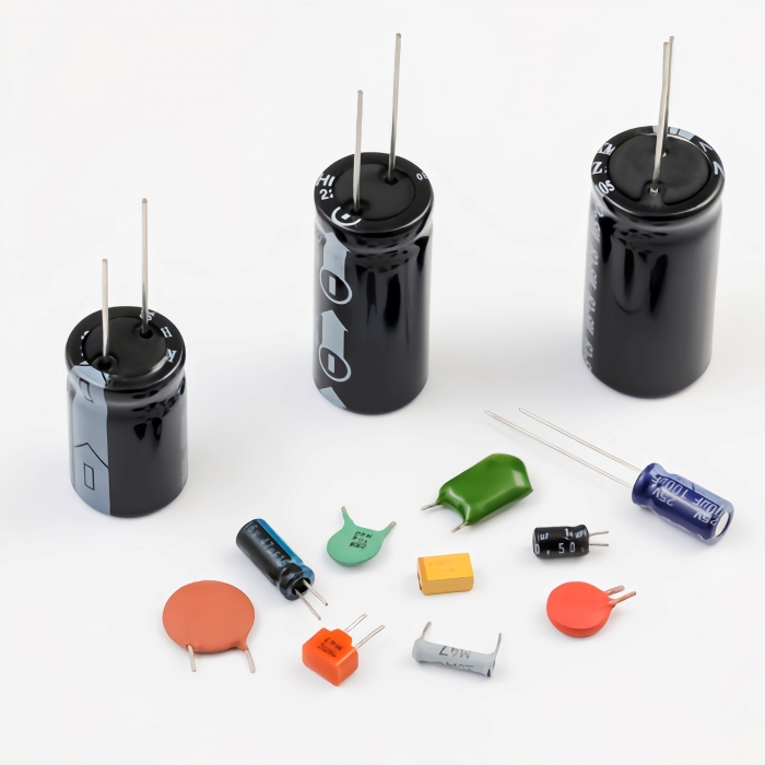
Common types
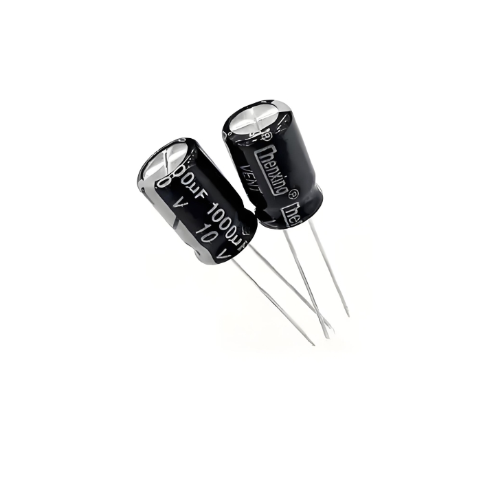
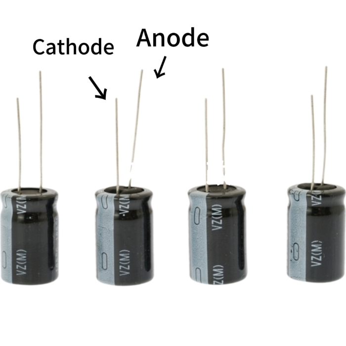
Aluminium Electrolytic Capacitor
Features aluminium foil electrodes and aluminium oxide dielectric. Offers low cost and high capacitance, suitable for power filtering and low-frequency circuits. However, it has a relatively short lifespan and is significantly affected by temperature.
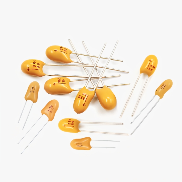
Tantalum Electrolytic Capacitors
It utilizes tantalum metal for the anode, tantalum oxide as the dielectric, and manganese dioxide or a polymer as the cathode (or part of the cathode layer). Features compact size, high stability, and low leakage current, making it suitable for high-precision circuits. However, it has a higher cost and lower high-voltage resistance.
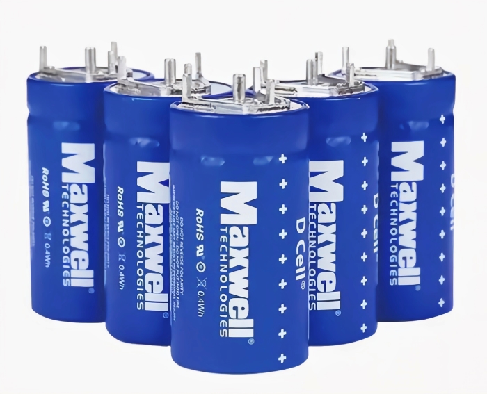
Supercapacitor
Also known as Electric Double-Layer Capacitors (EDLC), these utilize high-surface-area porous materials, such as activated carbon, as electrodes to maximize the surface area for charge accumulation. They offer far greater capacitance than traditional capacitors and feature rapid charge/discharge speeds, making them suitable for short-term energy storage and emergency power supply scenarios.
Polar vs Non-Polar Capacitors
Key Differences
Polar and non-polar capacitors exhibit significant differences in polarity requirements, structural principles, and performance characteristics.
|
Comparison of Dimensions |
Polar Capacitors |
Non-Polar Capacitors |
|
Polarity Characteristics |
Has clearly defined positive and negative terminals; must be connected to the circuit in the correct orientation |
No specific polarity; can be connected to the circuit in any direction |
|
Structural Differences |
Contains an electrolyte internally, storing energy through electrochemical effects |
Primarily composed of inorganic media (e.g., ceramics, thin films), storing energy through physical polarization |
|
Advantages |
High capacitance, relatively low cost |
Excellent high-frequency characteristics, low loss, long lifespan, stable performance |
|
Disadvantages |
Poor high-frequency performance, relatively short lifespan, and leakage current |
Typically lower capacitance, relatively larger size |
When to use polar capacitors
When you need a capacitor offering "high capacity, compact size, and low cost," choose polar capacitors. For instance, in power supply filtering to smooth alternating current ripple into a stable direct current, aluminium electrolytic or tantalum capacitors above 100 μF provide the best value. Similarly, for decoupling microcontrollers or amplifiers, they instantly supply current. As long as the voltage remains stable and polarity is fixed ( i.e., the positive terminal always connects to the positive power source), polar capacitors save both space and money. If circuits are at risk of voltage spikes or reverse polarity connections, switching to non-polar capacitors is still an option.
Equivalent Non-Polar Alternatives
• Non-polar replacements for polar capacitors:
In applications requiring small capacitance, non-polarized capacitors such as ceramic capacitors (MLCC) or film capacitors can be used to directly replace polarized capacitors like tantalum electrolytic capacitors, so as to completely avoid the risk of reverse polarity connection and improve high-frequency performance.
• Special-scenario substitutions:
In high-frequency circuits requiring large capacitance, the standard approach is to use bipolar/non-polar electrolytic capacitors or, more commonly, a combination of polar electrolytic capacitors in parallel with non-polar high-frequency ceramic capacitors to achieve a balance between high capacitance and excellent high-frequency response.
How to Identify Capacitor Polarity
Identifying capacitor polarity can be approached from three aspects: polarity marks on the PCB board, markings on the capacitor itself, and polarity indicators exclusive to tantalum electrolytic capacitors. You can also read our related article, Capacitor Symbol Analysis: Meaning, Types, and How to Read Them in Circuits.
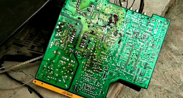
PCB Polarity Marks
On circuit boards, capacitor mounting locations typically feature explicit polarity markings, serving as the first line of defense against soldering errors.
• "+" Mark: The pad marked with a "+" sign corresponds to the positive terminal of the capacitor.
• Solid white line or thick line: An area outside the pad marked with a solid white line or thick line corresponds to the negative terminal. This is a very common marking.
• Silk Screen Fill: Occasionally, an entire pad area is filled with white silk screen ink. This filled area corresponds to the negative terminal.
Component Markings
Direct marking on the capacitor body is the most straightforward method for identification..
• Aluminium electrolytic capacitors: The longer lead is the positive terminal, and the shorter lead is the negative terminal. The side of the case marked with a "-" symbol corresponds to the negative terminal.
• Snap-In Electrolytic capacitors: The end face may be marked with "+" or "-" symbols or a color dot (the side with the color dot is usually the positive terminal in some older standards, but the negative terminal is the modern common mark)
• Some polarized film capacitors: The case is printed with an arrow or text indicating the positive terminal direction.
Polarity of Tantalum Electrolytic Capacitors
• Through-hole tantalum electrolytic capacitors: The "+" symbol is printed near the base of the leads, or the longer lead indicates the positive terminal. For metal-cased tantalum capacitors, the positive terminal is on the side with the engraved line at the top of the case.
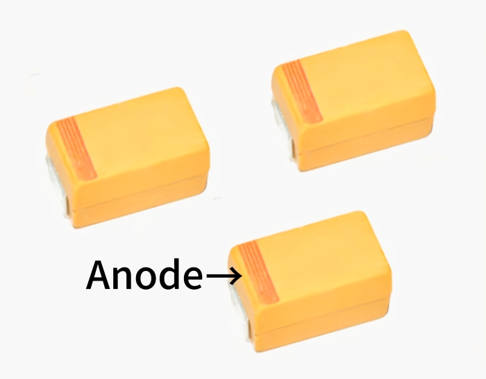
• Surface-mount tantalum electrolytic capacitors: The body surface typically displays color bands or a directly printed "+" symbol. Some types distinguish polarity solely by lead position (the lead near the marking side is positive).
How to Test a Capacitor With a Multimeter
Capacitance Mode
This is the most direct and recommended quantitative testing method.
• Discharge: Ensure the capacitor is fully discharged.
• Wiring: Set the multimeter to capacitance mode (symbol F or CAP). For polarized capacitors, ensure the red probe connects to the positive terminal and the black probe to the negative terminal.
• Reading: Read the capacitance value displayed on the screen.
• Evaluation:
Discharge: Ensure the capacitor is fully discharged.
Wiring: Set the multimeter to the high resistance range (e.g., R×1k or R×10k). For polarized capacitors, connect the red probe to the positive terminal and the black probe to the negative terminal (since the black probe is the positive terminal in the resistance mode of analog multimeters)."
Observation: Monitor the changing reading closely.
Digital meter: The resistance value starts from a small number and gradually increases until displaying "OL" or "1" (overflow). This confirms the charging process of the capacitor.
Analog Multimeter: The needle will first swing rapidly to the right (toward lower resistance) and then slowly return to the left (toward higher resistance).
Judgment:
Good: Noticeable charging/discharging phenomenon observed (resistance value continuously changes).
Short circuit: Resistance remains at zero or a minimal fixed value.
Open circuit: Resistance value consistently displays OL and shows no change.
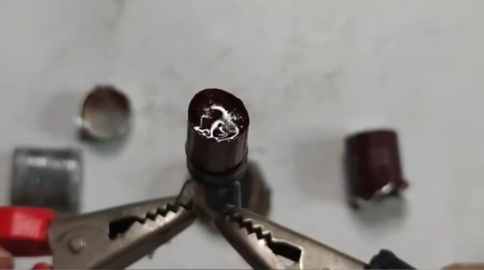
Real testing demo + video
Below is a video demonstrating how to test capacitor integrity:
A reverse voltage connection will disrupt the internal electrochemical balance of the capacitor, leading to electrolyte decomposition, breakdown of the dielectric material (electrolytic layer), a sharp increase in the capacitor's leakage current, accompanied by continuous heating, and instantaneous failure of its core performance.
Electrolyte Breakdown
Reversing polarity disrupts the electrochemical equilibrium within the capacitor, causing electrolyte decomposition and breakdown of the dielectric layer (the oxide layer). This results in a sharp increase in leakage current, accompanied by sustained heating, which leads to instantaneous failure of core performance.
Swelling & Explosion
Sustained heating generates significant gas buildup inside the capacitor, causing a rapid pressure increase. This leads to swelling of the casing and electrolyte leakage. If pressure exceeds the seal's limit, the capacitor may rupture. Splattered electrolyte can corrode circuits and damage surrounding components.
Real examples
• Aluminium electrolytic capacitors with reverse connection will cause the top explosion-proof vent to bulge, which leads to electrolyte leakage (brown corrosive liquid) and ultimately results in the corrosion of PCB traces.
• Tantalum electrolytic capacitors exposed to reverse voltage will cause the sintered pellet to overheat; this overheating makes the capacitor body blacken and the leads oxidize, and may even lead to the burning of nearby components (e.g., resistors).
Application Guide & Selection Tips
When selecting polarized capacitors, it is essential to consider not only the voltage ratings and capacitance but also proper matching based on specific application scenarios. Below are recommended practices and selection techniques for several common circuit applications:
Why do power supply filtering circuits require polar capacitors?
At power supply inputs and outputs, polar capacitors effectively suppress ripple voltage, absorb transient pulses, and filter noise. Their high capacitance smooths power fluctuations, ensuring stable operation of voltage regulators and connected loads.
Selection Recommendations:
• Select aluminium electrolytic capacitors with capacitance between 10μF and 1000μF.
• The voltage ratings should be 1.5 to 2 times that of the working voltage to avoid long-term overvoltage.
• For high-frequency switching power supplies, parallel a 0.1μF to 1μF ceramic non-polar capacitor with the polar capacitor to improve high-frequency response.
Why do audio circuits require polar capacitors?
In audio signal paths, polar capacitors enable audio signal coupling (blocking Direct Current components while transmitting Alternating Current audio signals) while bypassing high-frequency noise introduced by the power supply, thereby reducing signal distortion. Their low leakage current and low noise characteristics ensure the transmission of a pure audio signal, resulting in clearer and more stable sound quality.
Selection Recommendations:
•Select tantalum electrolytic capacitors or high-frequency aluminum electrolytic capacitors with a capacitance between 1μF and 10μF.
•The voltage ratings should be 1.5 to 2 times that of the circuit’s working voltage to prevent damage caused by overvoltage.
• Prioritize models with low ESR (equivalent series resistance) to minimize audio signal loss and avoid compromising sound quality.
Why do MCU decoupling circuits require polar capacitors?
In MCU power supply circuits, polar capacitors rapidly suppress transient voltage fluctuations at the power supply terminals. They provide instantaneous high-current supplementation to the MCU, preventing program runaway or performance anomalies caused by unstable power supply. Their low ESR (Equivalent Series Resistance) characteristics enable rapid response to current changes, enhancing decoupling effectiveness. (Note: Tantalum and Ceramic are preferred for low ESR decoupling; Aluminum electrolytic may have higher ESR but is used for bulk storage.).
Selection Recommendations:
• Select ceramic capacitors (MLCC) or tantalum electrolytic capacitors with capacitance between 0.1μF and 1μF for high-frequency decoupling. For bulk energy storage, use aluminum electrolytic or tantalum capacitors (e.g., 10 μF to 100 μF) near the power input.
• The voltage ratings should be no less than 1.2 to 1.5 times that of the MCU's working voltage, to balance safety and economy.
• Solder capacitors directly adjacent to MCU power pins. For significant high-frequency interference, parallel a 0.01μF to 0.1μF ceramic capacitor.
Datasheet Reading Tips
• Prioritize focusing on core parameters: Pay close attention to voltage ratings and nominal capacity to confirm they meet the circuit voltage margin (1.2 to 2 times the working voltage) and capacity requirements (e.g., 10μF to 1000μF for power supply filtering).
• Prioritize application-specific parameters: For power filtering circuits, emphasize ripple current; for audio circuits, focus on leakage current and low ESR; for MCU decoupling, consider package size and miniaturization compatibility.
• Correlate lifespan with temperature rise: Examine operating temperature ranges and lifespan curves to understand high-temperature degradation patterns (e.g., lifespan halves per 10°C temperature increase). Prevent premature failure caused by overlooked temperature rise.
• Verify polarity and packaging: Cross-reference polarity markings in datasheets with component/PCB wiring rules. Confirm that the packaging type (through-hole/surface mount) aligns with the soldering requirements to prevent installation errors.
• Consult Parallel Pairing Recommendations: Some manuals list recommended parallel capacitor models (e.g., ceramic capacitors for high-frequency applications). Directly reference these to optimize circuit response performance, aligning with the parallel solutions for different circuits discussed earlier.
• Supercapacitors: Focus on double-layer capacitance (EDLC) vs. pseudo-capacitance ratio, cycle life (≥100,000 cycles), and self-discharge rate (<1%/day at 25℃).
Mica/Glass Capacitors: Check DF (at 1kHz) and temperature coefficient (e.g., ±50ppm/℃ for precision applications).
• Bi-Polar/Non-Polar Electrolytic: Confirm AC voltage rating and reverse voltage tolerance (usually <10% of DC rating).
• Failure Rate: Refer to manufacturer’s MTBF (Mean Time Between Failures) data—silver mica capacitor and Nichicon MUSE series have ultra-low failure rates (<1 FIT, 1 failure per 10⁹ hours).
Recommended Polar Capacitor Series & Manufacturer
Panasonic
• FR Series: Long lifespan, low impedance, 105°C operating temperature. Suitable for general power supply filtering and industrial equipment. Recommended available products: EEUFR0J182, EEU-FR1V681.
• FM Series: Ultra-low ESR, high ripple current, suitable for high-frequency filtering in switching power supplies and CPU power supplies. Recommended available products include EEU-FM0J821L, EEUFM1C681.
•UPW (PW) Series: Low impedance, long lifespan, operating temperature 105°C. Suitable for general-purpose and power supply input/output filtering. Recommended available products include UPW0J101MDD, UPW0J102MPD.
•UFW (FW) Series: Audio-specific, low-loss, suitable for audio coupling, bypassing, and Hi-Fi equipment. Recommended available products include UFW0J102MPD and UFW0J103MHD.
Rubycon
•ZLH Series: Long lifespan (105°C for 10,000 hours), low impedance, suitable for high-performance power supplies, industrial, and automotive electronics. Recommended available products include 100ZLH470MEFC18X25, 100ZLH820M18X40.
KEMET / AVX
• Tantalum Series: Compact size, stable capacitance, low ESR, suitable for space-constrained power filtering and communication equipment. Recommended products include KEMET's T495D337M010ATE125(330 μF/10V) and T495D227K010ATE045(220 μF/10V), as well as AVX's TAJB157M004RNJ(150 μF/4V) and TAJB105K035RNJ(1 μF/35V).
Common Mistakes When Using Polar Capacitors
Reverse Polarity Connection
• Manifestation: Failure to distinguish polarity during installation, resulting in capacitor polarity opposing the circuit voltage direction.
• Core Consequences: Rapidly causes electrolyte layer breakdown and a surge in leakage current, leading to case swelling, electrolyte leakage, or even explosion, damaging surrounding circuits.
• Prevention: Verify capacitor markings against PCB polarity labels before installation. Use a multimeter to confirm polarity if uncertain.
Replacing Non-Polarized Capacitors with Polarized Ones
• Error Manifestation: Directly substituting polarized capacitors (e.g., aluminium electrolytic, tantalum electrolytic capacitors) for non-polarized capacitors (e.g., ceramic disc, film capacitors) in circuits.
• Core Consequences: Alternating Current circuits, circuits with reverse voltage, or circuits without a fixed Direct Current bias, the capacitor will fail rapidly, potentially causing short circuits or burnout.
• Mitigation: Strictly prohibit such replacements in Alternating Current or pulsating circuits. Consideration may be given only in theoretically pure DC-biased scenarios, but with extreme caution and as a non-recommended practice.
Ignoring Environmental Factors
• Manifestation: Failure to account for the actual operating conditions (humidity factor in humid environments, temperature factor in high-temperature circuits) during selection, and incorrectly using paper capacitors and supercapacitors regardless of their incompatible characteristics with such conditions—paper capacitors are not resistant to humidity (prone to DF/tan$\delta$ increase), and supercapacitors are sensitive to high temperatures (prone to lifespan decay due to thermal resistance).
• Core Consequences: Paper capacitors used in humid environments experience performance degradation (e.g., increased capacitance, leakage current, or dissipation factor) due to moisture ingress; supercapacitors used in high-temperature circuits suffer from lifespan decay caused by thermal resistance. Both issues directly affect the stable operation of the circuit or equipment.
• Mitigation: During selection, ensure the capacitor's environmental ratings match the application requirements: use capacitors with appropriate humidity resistance (e.g., IP67-rated capacitors for humid areas) instead of paper capacitors. For high-temperature circuit scenarios, use capacitors rated for high temperatures (e.g., 125°C or 150°C rated aluminum electrolytic capacitors) or ensure the operating temperature remains within the specified limits outlined in the datasheet to mitigate the impact of high temperatures on their lifespan.
Misselecting Capacitor Type for High-Frequency/High-Voltage
• Manifestation: Failure to account for the actual operating conditions (high frequency of RF broadcast transmitters, high voltage of high voltage inverters) during selection, and incorrectly using aluminum electrolytic capacitors regardless of their incompatible characteristics with such conditions.
• Core Consequences: Aluminum electrolytic capacitors lead to excessive signal attenuation and power loss (due to high ESR/ESL) when applied in RF broadcast transmitters and failure/breakdown when used in high voltage inverters
• Mitigation: During selection, choose capacitors that match the key operating parameters of the application: use MLCC or Film capacitors (e.g., Polypropylene) for general high-frequency filtering, and Silver Mica or Ceramic capacitors for precision RF applications. For high-voltage scenarios, use Film (Polypropylene) or Ceramic (Class 1) capacitors designed for HV applications. Meanwhile, refer to circuit laws (e.g., impedance vs. frequency) to verify the compatibility between the capacitor and the target circuit.