Capacitor Symbol Analysis: Meaning, Types, and How to Read Them in Circuits
Mastering capacitor symbols and capacitance values is fundamental to electronic circuit design, maintenance, and troubleshooting. Misinterpreting symbols or misreading values can cause circuit malfunctions, component damage, or even safety hazards. This article systematically breaks down capacitor symbol types, capacitance calculation methods, circuit identification techniques, and measurement methods to help professionals and learners efficiently grasp core concepts.
Understanding the Importance of Capacitor Symbols and Capacitance
In electronic engineering, the capacitor symbol serves as the "visual language" conveying capacitor characteristics, while capacitance (the core parameter determining capacitor functionality) complements it. Mastery of both directly impacts reliability throughout the entire circuit lifecycle—from design to application.
Why is learning capacitor symbols important?
The capacitor symbol serves as the "visual language" for communication among design, manufacturing, and maintenance teams in electronics engineering. Its learning value spans the entire circuit lifecycle, with three core reasons:
- Avoiding safety and functional risks: Capacitor symbols directly relate to component characteristics. For example, confusing polarized capacitors (symbols with a "+" sign or a curved line) with non-polarized capacitors (parallel line symbols) can lead to reverse-polarity soldering. This causes electrolyte leakage, bulging, or even circuit burnout in electrolytic capacitors. If a variable capacitor (symbol with an arrow) is mistakenly used as a fixed capacitor, the circuit may fail to achieve its intended parameter adjustment function (e.g., oscillation frequency calibration).
- Enhancing Work Efficiency: When interpreting circuit diagrams, proficiently recognizing capacitor symbols enables rapid identification of component functions. For instance, seeing the "straight line + curved line" symbol immediately indicates an electrolytic capacitor requiring polarity distinction, prompting priority verification of its connection to the power supply's positive terminal. During repairs, matching symbols to physical components enables swift determination of replacement part types (e.g., the "Tr" symbol for trimmer capacitors matches only identical-specification trimmers), preventing procurement and installation errors.
- Integration with professional knowledge systems: Capacitor symbols form the foundation for understanding capacitance units and measurement methods. For instance, the symbol "104K" can lead to learning the three-digit coding rule (the first two digits are significant figures, the third is the multiplier), enabling conversion to the actual capacitance (100 nF). Without recognizing basic symbols, subsequent unit conversion and parameter interpretation become impossible.
Capacitor Symbol Types and Schematic Representation Methods
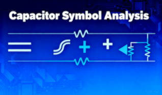
Based on polarity, function, and international standards, capacitor symbols fall into three major categories. Each symbol in schematics carries distinct functional meanings and must be accurately distinguished.
1. Basic Capacitor Circuit Symbols
Basic symbols distinguish polarity through line shapes and markings, representing the most common form in circuits:
- Non-polarized Capacitor Symbol
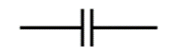
Composed of two parallel lines of equal length, indicating that the component has no specific polarity and can be connected to the circuit in either direction. Typical applications include ceramic and film capacitors.
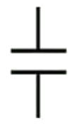
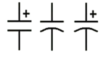
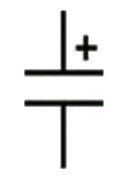
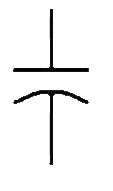
- Polarized Capacitor Symbol
Two primary representations exist:
-
- A single straight line (representing the positive terminal) paired with a curved line (representing the negative terminal);
- A straight line indicates the positive terminal, often labeled with a "+" sign. In contrast, the negative terminal is still represented by a curved line or omitted in some cases (depending on the circuit layout).
- A single straight line (representing the positive terminal) paired with a curved line (representing the negative terminal);
Typical applications of polarized capacitors include electrolytic capacitors and tantalum capacitors. When connecting to a circuit, the positive terminal must be connected to a high potential and the negative terminal to a low potential. A reverse connection will damage the component's internal dielectric layer, leading to failure.
2. Symbol Variants and International Standards (Capacitance and Capacitance Symbol Meaning)
Symbol standards vary slightly across regions and organizations. The actual application must adhere to the standards adopted by the project:
|
Standard System |
Polarized Capacitor Symbol |
Voltage-dependent capacitor symbol |
|
Institute of Electrical and Electronics Engineers (IEEE) |
Positive terminal marked with a "+" sign; negative terminal lacks curved lines (represented only by a short straight line)
|
A shape with a short parallel line on each side to indicate voltage dependency.
|
|
International Electrotechnical Commission (IEC) |
Positive terminal represented by a long straight line; negative terminal represented by a curved line (without a "+" sign)
|
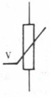
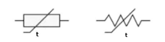
A rectangle with a diagonal line through the center, accompanied by a small "V" or arrow beside the diagonal line.
|

3. Special Capacitor Symbols
For capacitors with special functions or structures, their symbols include additional markings to reflect their characteristics:
- Variable/trimmer capacitor Symbols
Specific functional markers are added to the non-polar capacitor symbol for differentiation:
-
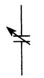
- Variable Capacitor (e.g., air variable capacitor): An arrow pointing toward one of the parallel lines is added, indicating the capacitance value can be adjusted over a wide range.
- Variable Capacitor (e.g., air variable capacitor): An arrow pointing toward one of the parallel lines is added, indicating the capacitance value can be adjusted over a wide range.
-
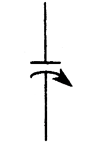
- Trimmer Capacitor (e.g., ceramic trimmer capacitor): A small rotary symbol (or the abbreviation "Tr" for "Trimmer") is added beside the parallel lines, indicating the capacitance value can only be adjusted in small increments (typically used for circuit calibration).
- Trimmer Capacitor (e.g., ceramic trimmer capacitor): A small rotary symbol (or the abbreviation "Tr" for "Trimmer") is added beside the parallel lines, indicating the capacitance value can only be adjusted in small increments (typically used for circuit calibration).
- Feed-through capacitor symbol
The symbol consists of two parallel plates (two parallel lines) and a straight line passing through their center.
- Bipolar capacitor symbol
Formed by two polarized capacitor symbols connected in series with their polarities reversed (positive lines facing each other), indicating the component can withstand bidirectional voltage. Suitable for AC circuits or applications with undefined polarity (e.g., audio coupling circuits). The symbol lacks a "+" sign, curved lines, or any other polarity indicators. This signifies the capacitor can be connected to the circuit in either direction.
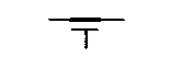
- Temperature-Dependent Capacitor (TDR) Symbol
A "T" appended to the non-polar capacitor symbol indicates that the capacitance value varies with temperature (e.g., certain ceramic capacitors). Careful selection is required in temperature-sensitive circuits.
Understanding Capacitance Quantity: Capacitance Formula, Units, and Values
Capacitance value is the core parameter of a capacitor. Its physical essence must be understood through the formula, and combined with unit conversion rules and coding interpretation methods to accurately read capacitance values.
1. Capacitance Formula and Physical Meaning
The magnitude of a capacitor's capacitance is determined by its physical structure. The core formula and influencing factors are as follows:
- Basic capacitance formula: C = Q/V
 , where:
- C represents capacitance value (unit: farad, symbol F);
- Q is the charge stored on the capacitor plates (unit: coulomb, symbol C);
- V is the applied voltage across the capacitor terminals (unit: volt, symbol V).
- C represents capacitance value (unit: farad, symbol F);
Physical Meaning: At a fixed voltage, a larger capacitance value indicates a greater ability of the plates to store charge, reflecting the strength of the capacitor's "energy storage capacity."
- Key factors affecting capacitance (based on the parallel-plate capacitor model):
Formula: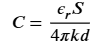 (where k is the electric constant).
This formula explains why ceramic capacitors of the same capacitance are significantly smaller than electrolytic capacitors, because ceramic has a much higher dielectric constant than electrolytic paper.
-
- Plate area (S): A larger plate area increases capacitance (the two are directly proportional) — a larger plate area can accommodate more charge;
- Dielectric constant (ε) of the medium between plates: Higher dielectric constant yields greater capacitance (directly proportional) — Different materials (e.g., ceramic, electrolytic paper) possess varying energy storage capacities;
- Distance between plates (d): The smaller the distance between plates, the greater the capacitance value (inversely proportional) — Closer plates create a stronger electric field strength between them, increasing the attractive force between charges.
- Plate area (S): A larger plate area increases capacitance (the two are directly proportional) — a larger plate area can accommodate more charge;
2. Capacitance Units Symbol, and Conversions
The fundamental unit of capacitance is the "farad (F)." However, due to its impracticality in real-world applications, derived units are commonly used instead. The conversion relationships between these units must be accurately memorized:
|
Unit Name |
Symbol |
Conversion Relationship with Farad (F) |
Typical Application Scenarios |
|
Picofarad (pF) |
pF |
High-frequency circuits (e.g., RF filtering), small-capacitance capacitors (e.g., ceramic capacitors) |
|
|
Nanofarad (nF) |
nF |
1 nF = 10⁻⁹ F |
Mid-frequency circuits (e.g., audio coupling), medium-capacitance capacitors |
|
Microfarad (μF) |
μF |
1 μF = 10⁻⁶ F |
Low-frequency circuits (e.g., power supply filtering), large-capacitance capacitors (e.g., electrolytic capacitors) |
|
Millifarad (mF) |
mF |
1 mF = 10⁻³ F |
Rarely used, only in ultra-high-capacity energy storage applications (e.g., certain industrial power supplies) |
Note: In datasheets and schematics, unit symbols are often omitted. Determine the unit based on the numerical value (e.g., "10" in high-frequency circuits typically denotes 10 picofarads; in power circuits, it usually denotes 10 microfarads).
3. Capacitor Value Identification, Capacitor Code, and Coding Methods
Capacitor values are primarily marked using two methods: "Direct Marking" and "Numeric Coding." Select the appropriate interpretation method based on the marking format:
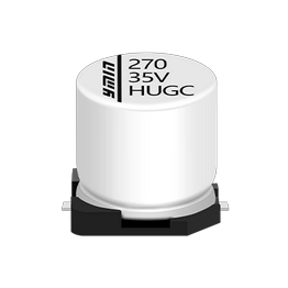
- Direct Marking Method
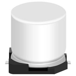
Capacitance values and units are directly printed on the capacitor body or in the datasheet. This straightforward interpretation method is commonly used for high-capacitance components (e.g., electrolytic capacitors):
-
- Example 1: "10μF 16V" — Indicates a capacitance of 10 microfarads and a rated voltage of 16 volts;
- Example 1: "10μF 16V" — Indicates a capacitance of 10 microfarads and a rated voltage of 16 volts;
-
- Example 2: "220nF" — indicates a capacitance of 220 nanofarads (equivalent to 0.22 microfarads).
- Example 2: "220nF" — indicates a capacitance of 220 nanofarads (equivalent to 0.22 microfarads).
- Numeric Coding Method
Primarily used for small-capacity capacitors (e.g., ceramic capacitors), employing a "three-digit code + letter tolerance" format. Core rules are as follows:
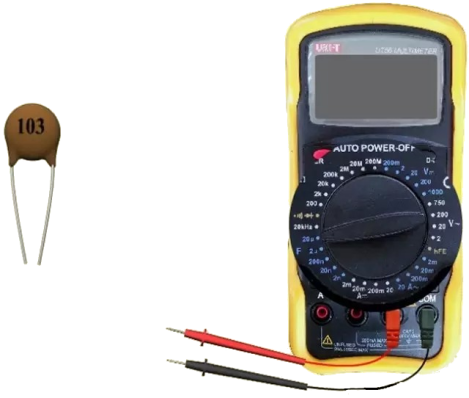
Complete example: "104K" — indicates a capacitance of 100 nanofarads with a tolerance range of ±10%.
-
- Three-digit code: The first two digits are significant figures, while the third digit represents the "multiplier" (i.e., a power of 10). The unit is implicitly picofarads (pF).
- Three-digit code: The first two digits are significant figures, while the third digit represents the "multiplier" (i.e., a power of 10). The unit is implicitly picofarads (pF).
-
-
- Example 2: "000" — Indicates a capacitance value of 0 pF (i.e., piaceholder/jumper, commonly used as a placeholder during circuit debugging);
- Example 2: "000" — Indicates a capacitance value of 0 pF (i.e., piaceholder/jumper, commonly used as a placeholder during circuit debugging);
-
-
- Letter Tolerance: Immediately following the three-digit code, it represents the permissible deviation range of the capacitance value. Common tolerance grades are as follows:
- Letter Tolerance: Immediately following the three-digit code, it represents the permissible deviation range of the capacitance value. Common tolerance grades are as follows:
|
Tolerance Letter |
Allowable Deviation Range |
Applicable Capacitor Types |
|
J |
±5% |
High-precision capacitors (e.g., tantalum capacitors) |
|
K |
±10% |
Medium-precision capacitors (e.g., ceramic capacitors) |
|
M |
±20% |
Standard-tolerance capacitors (e.g., film capacitors) |
Identifying Capacitor Symbols in Schematics
When identifying capacitor symbols in schematics, a comprehensive assessment of "symbol shape," "annotation information," and "circuit function" is essential to avoid confusion with other components and prevent common misidentifications.
1. How to Quickly Identify Capacitor Schematic Symbol
Master these three core identification techniques to locate capacitors in schematics within 10 seconds:
- Observe symbol shape: Prioritize checking whether the symbol features "parallel lines" (non-polar capacitors) or "straight lines + curved lines / '+' sign" (polar capacitors). This is the core distinguishing feature of capacitor symbols, clearly differentiating them from resistor (rectangular) and inductor (coil-shaped) symbols.
- Check the prefix: Components in schematics are typically labeled with fixed letter prefixes. Capacitors use the prefix "C," such as "C1" or "C20." If the prefix is "R" (resistor) or "L" (inductor), you can immediately rule out the possibility of a capacitor.
- Consider routing logic: If the symbol connects to a power supply positive terminal (e.g., VCC) and features a "+" sign or curved line, it is likely a polarized capacitor (e.g., electrolytic capacitor). If the symbol resides in a high-frequency signal path (e.g., RF circuitry) without polarity indicators, it is typically a ceramic or film capacitor.
2. Common Misidentification Cases and Standards for the Symbol for Capacitor
In practice, capacitor symbols are easily confused with resistors, inductors, and other components. Typical cases clarify differentiation methods:
- Confusion between polarized and non-polarized capacitor symbols:
-
- Misjudgment Case: Mistaking the "curved line" of a polarized capacitor for the parallel lines of a non-polarized capacitor, leading to the reverse connection of the component. For example, connecting an electrolytic capacitor with a curved line symbol, as if it were a ceramic capacitor, may cause leakage within 10 seconds of powering on after a reverse connection.
- Misjudgment Case: Mistaking the "curved line" of a polarized capacitor for the parallel lines of a non-polarized capacitor, leading to the reverse connection of the component. For example, connecting an electrolytic capacitor with a curved line symbol, as if it were a ceramic capacitor, may cause leakage within 10 seconds of powering on after a reverse connection.
-
- Prevention Method: Remember that "a curved line or '+' sign always indicates polarity." Only parallel lines without any additional markings represent non-polar capacitors.
- Prevention Method: Remember that "a curved line or '+' sign always indicates polarity." Only parallel lines without any additional markings represent non-polar capacitors.
- Distinguishing between Resistor and Inductor Symbols:
|
Component Type |
Core Symbol Feature |
Prefix Notation |
Circuit Function Differences |
|
Capacitor |
Parallel lines (non-polarized) / Straight line + curved line (polarized) |
C |
Passes AC, blocks DC; used for filtering and coupling. |
|
Resistor |
Rectangular (or folded), no parallel structure |
R |
Current limiting, or voltage division, is used to control current and voltage. |
|
Inductor |
Coil-shaped (typically 3-5 turns of folded wire), no parallel wires |
L |
Allows DC, blocks AC; used for energy storage and filtering. |
Misinterpretation Case: Mistaking the "coil-shaped" inductor symbol for a capacitor symbol — If an inductor (L) is mistakenly used as a capacitor (C) in a power supply filter circuit, the circuit will fail to filter out AC ripple, resulting in increased output voltage fluctuations.
Mastering Capacitor Measurement: How to Determine Capacitance
Capacitance measurement requires a multimeter (or LCR meter). Select appropriate measurement tools and equipment as follows:
|
Scenario Type |
Capacitor Characteristics (Capacitance / Type) |
Accuracy Requirement |
Recommended Equipment |
Key Considerations |
|
Routine Maintenance |
1nF to 1000μF (Ceramic / Electrolytic) |
±10% to ±20% |
Digital Multimeter with Capacitance Range |
Portable, fast, low-cost |
|
Laboratory R&D |
1 pF to 10 mF (high-frequency / precision capacitance) |
±0.1% to ±1% |
High-Precision LCR Meter |
Multi-frequency, multi-parameter (tanδ/ESR) |
|
Industrial Quality Control |
Full Specifications (Through-Hole / Surface Mount, Batch) |
±5% to ±10% |
Fully Automated LCR Test System |
Automated, high-efficiency, traceable |
Operations must strictly follow procedural steps while prioritizing safety and precision to prevent measurement errors or component damage from improper handling.
1. Multimeter Capacitance Measurement Symbol Steps
1.1 Multimeter Capacitance Symbols
There are two primary symbols for capacitance measurement on a multimeter. Verify the setting before operation:
- Main symbol: "–|(–" (resembling a simplified capacitor plate diagram);
- Alternative Marking: Some multimeters directly label "Cap" (abbreviation for "Capacitor") or "C". Range scales are typically denoted by "μF", "nF", or "pF" (e.g., 200pF, 2μF, 200μF).
Important Note: If the multimeter lacks a dedicated capacitance measurement range (e.g., on certain basic analog multimeters), direct capacitance measurement is not possible. Switch to an alternative piece of equipment (e.g., a digital multimeter or LCR meter).
1.2 Capacitance Measurement Procedure
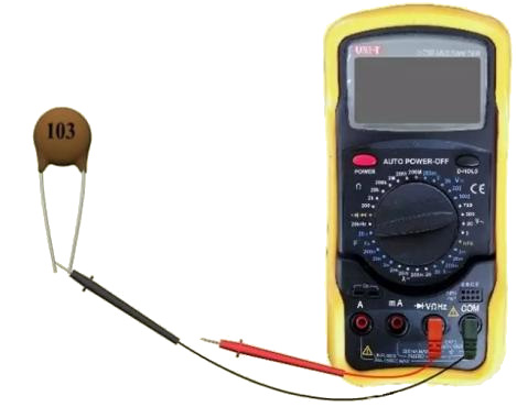
Using a digital multimeter to measure a 0.01μF (10³) capacitor as an example, follow these three steps to ensure safe operation and measurement accuracy:
Step 1: Power Off / Discharge (Critical Step):
-
- If the capacitor is soldered into a circuit, first disconnect the circuit's power source. Then use a screwdriver (or wire) to short-circuit both terminals of the capacitor (for at least 5 seconds) to discharge any residual charge within the component. Failure to discharge may damage the multimeter or cause measurement errors.
- For unmounted individual capacitors, verify no residual charge remains internally (by shorting the terminals).
- If the capacitor is soldered into a circuit, first disconnect the circuit's power source. Then use a screwdriver (or wire) to short-circuit both terminals of the capacitor (for at least 5 seconds) to discharge any residual charge within the component. Failure to discharge may damage the multimeter or cause measurement errors.
Step 2: Select Range:
-
- Select an appropriate range based on the estimated capacitance, following the principle of "slightly exceeding the estimated value" — for example, when measuring a 100 nF (0.1 μF) capacitor, choose the "2 μF" range (not "200 nF" or "20 μF"). A range that is too small will cause overflow (displaying "OL"), while a range that is too large will reduce measurement accuracy. Estimate the capacitance to select an appropriate range; the closer the range to the capacitance value, the more accurate the reading. If estimation is not possible, choose the maximum value of 20 μF.
- Select an appropriate range based on the estimated capacitance, following the principle of "slightly exceeding the estimated value" — for example, when measuring a 100 nF (0.1 μF) capacitor, choose the "2 μF" range (not "200 nF" or "20 μF"). A range that is too small will cause overflow (displaying "OL"), while a range that is too large will reduce measurement accuracy. Estimate the capacitance to select an appropriate range; the closer the range to the capacitance value, the more accurate the reading. If estimation is not possible, choose the maximum value of 20 μF.
Step 3: Connect the probes and read the value:
-
- Non-polarized capacitors: Connect the multimeter's red and black probes to any two pins of the capacitor without distinguishing polarity.
- Non-polarized capacitors: Connect the multimeter's red and black probes to any two pins of the capacitor without distinguishing polarity.
-
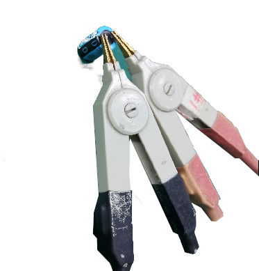
- Polarized capacitors: Connect the red probe to the positive terminal (marked "+") and the black probe to the negative terminal (corresponding to the curved line). Reversing polarity may cause measurement errors exceeding 30%.
- Polarized capacitors: Connect the red probe to the positive terminal (marked "+") and the black probe to the negative terminal (corresponding to the curved line). Reversing polarity may cause measurement errors exceeding 30%.
-
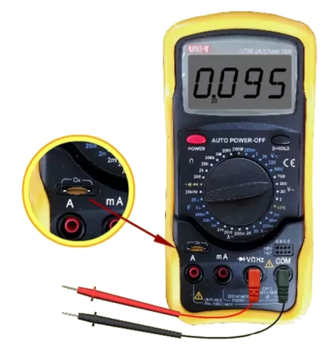
- Insert the capacitor into the multimeter's capacitance socket, turn on the multimeter power switch, and observe the reading. The measured capacitance is: 0.095μF. This capacitance value is relatively small; using the two μF range yields a closer, more accurate measurement.
- Insert the capacitor into the multimeter's capacitance socket, turn on the multimeter power switch, and observe the reading. The measured capacitance is: 0.095μF. This capacitance value is relatively small; using the two μF range yields a closer, more accurate measurement.
-
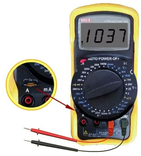
- Rotate to the 2μF capacitance range. The measured capacitance is: 0.103μF.
- Rotate to the 2μF capacitance range. The measured capacitance is: 0.103μF.
-
- After the multimeter display stabilizes (typically 1-2 seconds), read the measured value: - If the displayed value deviates from the capacitor's nominal value within the allowable tolerance range (e.g., a "104K" capacitor measured between 95 nF and 105 nF), the capacitor is functional. If the deviation exceeds the tolerance range (e.g., a "104K" capacitor measures only 50 nF), the capacitor is defective.
- After the multimeter display stabilizes (typically 1-2 seconds), read the measured value: - If the displayed value deviates from the capacitor's nominal value within the allowable tolerance range (e.g., a "104K" capacitor measured between 95 nF and 105 nF), the capacitor is functional. If the deviation exceeds the tolerance range (e.g., a "104K" capacitor measures only 50 nF), the capacitor is defective.
2. Core Parameters and Measurement Steps for Capacitance Testing with an LCR Meter
2.1 Core Parameters for Capacitance Measurement with LCR Meters
An LCR meter can measure multiple key parameters of capacitors, which must be preset based on the test objective. Core parameters are as follows:
- Capacitance (C): Core measurement value, units: pF, nF, μF, mF. Select a range matching the capacitor's nominal value to ensure accurate readings.
- Tangent of loss angle (tanδ): Reflects the degree of energy loss in the capacitor. For high-frequency capacitors (e.g., RF circuit capacitors), tanδ must be controlled below 0.001 to prevent signal distortion.
- Equivalent Series Resistance (ESR): Affects capacitor charging/discharging efficiency. Test ESR for tantalum capacitors in fast-charging circuits, typically requiring <50mΩ to prevent circuit overheating.
- Test Frequency (f): Must match the capacitor's actual operating frequency. High-frequency capacitors should be tested at 1 MHz to 10 MHz, while standard electrolytic capacitors should be tested at 100Hz to 1kHz.
- Precautions: Select the appropriate equivalent model for different capacitor types. High-frequency capacitors commonly use the "series model," while large-capacity electrolytic capacitors typically use the "parallel model." Incorrect model selection can cause measurement errors exceeding 20%.
2.2 Steps for Measuring Capacitance with an LCR Meter
LCR meters primarily measure capacitance and inductance. Capacitance is typically measured in parallel (P). Capacitance Test Items: Capacitance value - Loss angle (CP-D), Equivalent series resistance (Cs-Rs);
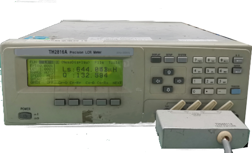
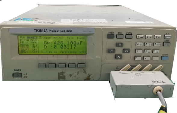
Measuring Capacitance Value and Loss Angle (CP-D) (Example: 50V, 470μF)
Step 1: Locate the datasheet and identify the nominal capacitance—470μF and operating frequency—120Hz
Step 2: Connect both terminals of the electrolytic capacitor (polarity does not matter), press the button to select CP-D, and input frequency 120Hz.
3. Measurement Precautions and Common Pitfalls
Avoiding these six common pitfalls can improve capacitance measurement accuracy to over 90%:
- Avoid direct measurement in circuits: Other components (e.g., resistors, inductors) introduce interference, causing over- or under-readings. For instance, measuring a 100 μF capacitor in a power filter circuit without removal may show 80 μF due to resistive shunting (while the capacitor itself functions normally).
- Avoid reverse polarity connections: Reverse polarity not only causes measurement errors but may also induce internal currents that damage the multimeter's capacitance measurement module (especially with high-voltage capacitors like 400V electrolytic capacitors).
- Eliminate environmental interference: Humid conditions (relative humidity >80%) increase probe contact resistance, leading to lower readings. Measure in dry environments or clean capacitor leads and probes with alcohol.
- Do not measure capacitors with excessively low capacitance: The minimum precision of a multimeter's capacitance range is typically one pF. If measuring capacitors with capacitance < 1 pF (e.g., certain high-frequency capacitors), measurement errors may exceed 50%. In such cases, an LCR meter must be used.
- Ensure complete capacitor discharge: If residual internal charge remains, the multimeter initially displays a higher value that gradually decreases, leading to misinterpretation as "capacitance decay." Adequate short-circuit discharge time is essential (10 seconds or more for large-capacitance components).
- Distinguish between "capacitance deviation" and "failure": If the measured value slightly exceeds tolerance limits (e.g., a "104K" capacitor reads 106 nF, a +6% deviation exceeding ±10% tolerance), but shows no leakage or bulging, it remains usable in non-critical circuits (such as standard filter circuits). If the measured value is zero or significantly below the nominal value (e.g., a "104K" capacitor measures only 10 nF), the capacitor is considered failed and must be replaced.
Application Scenarios and Summary
Capacitor symbols carry distinct functional meanings across different application circuits. Understanding their corresponding relationships enables rapid comprehension of circuit design intent. Crucially, core principles must be memorized to prevent operational errors.
1. Symbol Position in Typical Application Circuits
The type and labeling of capacitor symbols follow specific patterns across different circuit functions, allowing quick identification by context:
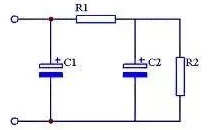
- Filter circuits: Typically employ polarized capacitors (symbols include a "+" sign or curved line), with larger rated capacities (e.g., "C1: 1000μF 16V"). These are usually connected between the positive power supply terminal and ground to filter out AC ripple.
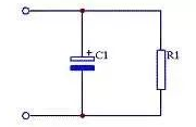
Capacitor Filter Circuit Diagram
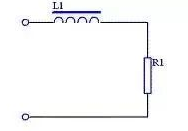
Inductive Filter Circuit Diagram
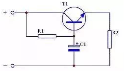
PC Filter Circuit Diagram
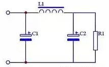
LC filter circuit diagram
Active filter circuit diagram
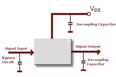
- Decoupling Circuit: Typically employs non-polarized capacitors (parallel lines symbol), marked with smaller capacitance values (e.g., "C2: 0.1μF"), usually positioned near the power pins of integrated circuits (ICs) to suppress high-frequency noise;
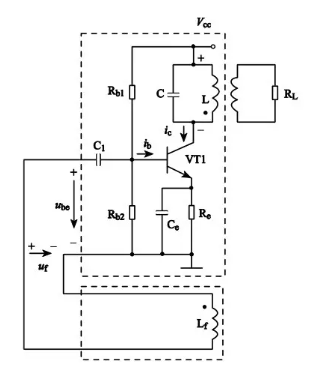
- Oscillation Circuit: Often employs variable capacitors (arrow symbol) or high-precision non-polarized capacitors (e.g., "C3: 100pF J"), connected in series/parallel with inductors (L) to form LC oscillation circuits that determine oscillation frequency;
- Timing circuits: Typically employ polarized capacitors (e.g., "C4: 10μF 5V") paired with resistors (R) to form RC charging/discharging circuits. The capacitor's charging/discharging times control circuit timing (e.g., the output duration of monostable triggers).
2. Summary and Practical Recommendations
This article systematically outlines key concepts surrounding capacitor symbols, units, measurement methods, and application scenarios, while addressing common questions to facilitate precise application of capacitor knowledge in circuit design and maintenance.
Core Knowledge Review
- Capacitor Symbols: Basic symbols include non-polar (parallel lines) and polar (straight line + curved line / "+" sign); note variations between IEEE and IEC standards; specialized symbols (e.g., through-hole, bipolar) have dedicated markings; variable/trimmer capacitors are distinguished by arrow and rotation symbols, respectively.
- Capacitance Units and Values: The fundamental unit is the farad (F). Standard derived units include pF, nF, and μF, with conversion relationships: 1 μF = 1000 nF = 10⁶ pF. Value reading methods include direct marking (e.g., "10μF 16V") and numerical coding (e.g., "104K" = 100nF ±10%).
- Measurement Method: Use the capacitance setting on a multimeter (symbol "–|(–" or labeled "Cap"/"C"). First disconnect power and discharge the capacitor, then select the appropriate range. For polarized capacitors, connect the red probe to the positive terminal and the black probe to the negative terminal. Finally, read the stable value. Avoid common pitfalls, such as measuring directly in the circuit.
Design and Practical Recommendations
- Dual Polarity Verification: During design and soldering, first confirm polarized capacitor symbols ("+" sign / curved line) against the schematic. Then cross-check the PCB silkscreen or physical pin markings to ensure that the positive terminal connects to the high-potential terminal and the negative terminal connects to the low-potential terminal. Avoid reverse connections, which can cause leakage or burnout.
- Component Selection and Matching: Choose capacitor types based on circuit function—e.g., small-capacity non-polar ceramic capacitors for high-frequency circuits, large-capacity polar electrolytic capacitors for power filtering. When replacing components, ensure the symbol matches the original part's type, capacitance value, and tolerance.
- Regular Inspection and Maintenance: Periodically measure capacitance values of critical circuit capacitors using a multimeter. Replace immediately if deviation exceeds the tolerance range or if leakage/bulging occurs to ensure stable circuit operation.
FAQs:
Understanding Capacitance Quantity — What symbol represents capacitance?
Capacitance (C) represents a capacitor's storage capacity and is the core parameter that determines its energy storage capability. Its physical meaning can be understood from the formula C = Q/V: at a fixed voltage, a higher capacitance allows for greater stored charge. In circuit calculations and annotations, "C" represents this physical quantity. For example, "C1=10μF" indicates that capacitor C1 has a capacitance of 10 microfarads.
Capacitor Symbol Types and Schematic Representation — What are capacitor symbols?
Capacitor symbols can be categorized into three main types:
Basic Symbols: Non-polar capacitors are represented by two parallel lines of equal length; polar capacitors are depicted as "straight line + curved line" or "straight line with a '+' symbol + curved line," corresponding to the positive and negative terminals, respectively.
Variant symbols: Influenced by international standards, IEEE standards mark the positive terminal of polarized capacitors with a "+" sign and omit the curved line for the negative terminal. IEC standards use a long straight line for the positive terminal and a curved line for the negative terminal, without a "+" sign.
Special symbols: Through-hole capacitors are represented by parallel lines with a central through-line; temperature-dependent capacitors are marked with a "T" symbol.
Capacitor Symbol on a Multimeter
There are primarily two symbols for capacitance measurement on a multimeter:
Mainstream symbol: Represented by "–|(–", this symbol mimics the structure of a capacitor's two plates, intuitively reflecting capacitance characteristics. It is the identification method used by most multimeters.
Alternative labeling: Some multimeters directly display "Cap" (abbreviation for "Capacitor") or "C". The measurement range is indicated in units such as "μF", "nF", or "pF" (e.g., "200pF", "2μF"), allowing users to select the appropriate range based on their estimated capacitance.
Capacitance Unit Conversion and Interpretation
Understand the conversion relationships between the fundamental unit farad (F) and its derived units (μF, nF, pF) (1μF = 1000nF = 10⁶pF). Also note methods for interpreting units when abbreviated (e.g., "10" typically denotes 10 pF in high-frequency circuits and "10" in power circuits usually denotes 10 μF), thereby resolving unit confusion in practical applications.
How to Accurately Measure Capacitance Values
Step-by-step explanation of multimeter measurement procedure (de-energize and discharge → select range → connect probes → read value), emphasizing polarized capacitor probe connection rules (red probe to "+", black probe to "-"). Common pitfalls are listed (e.g., measurement errors due to undischarged capacitors, interference during in-circuit measurement) to ensure measurement accuracy.
How to Read Capacitance Values from Markings
Covers two labeling methods: direct notation (e.g., "10μF 16V") with intuitive interpretation, and numerical coding (e.g., "104K") with rule breakdown (first two significant digits + third multiplier digit + tolerance letter). Examples (e.g., "104K" = 100 nF ±10%) help readers master capacitance calculations and avoid misreading codes.
Capacitor Symbol Recognition in Circuit Schematics
Representing capacitors in schematics requires integrating symbol form, annotation details, and circuit function:
Symbol Selection: Choose symbols based on capacitor polarity and type. Non-polar capacitors use parallel lines; polar capacitors use "straight line + curved line / '+' sign." Add a rotation symbol or label "Tr" for trimmer capacitors.
Labeling Information: Prefix components with "C" (e.g., "C1", "C20") to identify them as capacitors. Simultaneously label capacitance value and unit (or code), such as "C3: 104K" or "C4: 10μF 5V". Some may also include rated voltage and other parameters.
Routing Association: Capacitor symbol connections must align with circuit function. For example, filter capacitors connect between the power supply positive and ground, while decoupling capacitors are routed near IC power pins. Positioning further clarifies the capacitor's purpose.
Symbol Variants and International Standards—What is the difference between the standard capacitance symbol and variable capacitance symbols?
The core differences between standard capacitor symbols (using non-polar and fixed polar capacitors as examples) and variable capacitor symbols lie in functional markings and application scenarios:
Symbol Form: The standard non-polar capacitor symbol consists of two parallel lines, while the standard polar capacitor symbol features a "straight line + curved line / '+' sign." Variable capacitor symbols add an arrow pointing to one of the parallel lines on the non-polar capacitor base, indicating a wide-range adjustable capacitance.
Functional Differences: The standard capacitor symbol represents a fixed-capacitance component incapable of adjustment, suitable for applications such as filtering and coupling where parameter adjustment is unnecessary. The variable capacitor symbol denotes a capacitance-adjustable component, with the arrow highlighting its tunable nature. It is ideal for scenarios requiring flexible parameter adjustment, such as oscillation frequency calibration.
Subtypes: Variable-capacitor symbols are further categorized into standard variable capacitors (arrow only) and trimmer capacitors (with a rotation symbol or "Tr" notation). Trimmer capacitors offer finer adjustment ranges, primarily used for precise circuit calibration, while standard capacitor symbols lack such distinctions.
Common Issues Encountered in Schematics/PCBs/Datasheets (Identification, Polarity, Capacitance Errors)
In practical applications, capacitor-related issues in schematics, PCBs (printed circuit boards), and datasheets primarily fall into three categories: identification, polarity, and capacitance value. Specific scenarios include:
Identification errors: Component misjudgment due to symbol confusion
|
Error Category |
Error Scenario |
Specific Manifestation |
Consequences |
|
Symbol Recognition Error |
Circuit Diagram Symbol Confusion |
1. Capacitor "parallel lines" misidentified as resistor "rectangles"; 2. Inductor "coil shape" misidentified as a capacitor |
1. Filter circuit failure, unable to filter ripple; 2. Loss of high-frequency interference suppression in power supply circuits |
|
Symbol Recognition Errors |
PCB Silkscreen Fading |
Ceramic capacitor (silkscreen "C + number") misidentified as surface-mount resistor (silkscreen "R + number") |
Requires desoldering and replacement, increasing labor hours |
|
Incorrect polarity connection |
Deviation between Circuit Diagram and PCB |
Schematic labels the capacitor with "+", PCB silkscreen lacks polarity indication; soldered based on experience. |
Capacitor reverse-connected, failed after power-up |
|
Incorrect polarity connection |
Mismatch between physical component and schematic symbol |
Electrolytic capacitor labeled only with "-", without reference to schematic rule "curved line indicates negative terminal"; incorrect polarity connection |
Circuit short-circuited |
|
Capacitance value misinterpretation |
Misreading datasheet codes |
Mistaken Interpretation:Reading'223'as 223 pF.CorrectValue:22xthird digit'3' is the multiplier1000). |
Insufficient capacitance, e.g., excessive ripple voltage in filtering |
|
Capacitance value misinterpretation |
PCB silkscreen unit omission |
In high-frequency circuits, "10" (actual 10pF) is soldered incorrectly as 10μF |
Capacitance value too large, causing abnormal high-frequency circuit behavior (e.g., signal attenuation) |
Recommended Resistor:
Symbol of Varistor: From Theory to Practice