How to Convert AC to DC: Complete Guide to Converters, Circuits, and Efficiency
What is AC?
Alternating current (abbreviated as AC) is a current whose direction periodically changes. Compared with direct current (DC), AC has many advantages, such as reduced transmission losses and lower costs for power generation and transformer manufacturing. Consequently, AC power is widely adopted in electric systems. To manage and utilize alternating current more flexibly, various power electronic devices have emerged, with AC converters playing a central role. These devices enable precise control over AC parameters, such as AC-to-AC power converters, which further expand the application scope of alternating current.
Generation of Alternating Current
Alternating current is generated by an alternator. An alternator primarily consists of two parts: the stator and the rotor. The stator typically contains multiple sets of coils (such as three-phase windings) for outputting alternating current; the rotor is usually an excitation winding or a permanent magnet, which generates alternating current in the stator coils through the principle of electromagnetic induction. When the rotor rotates, alternating current is generated in the stator coils due to the principle of electromagnetic induction.
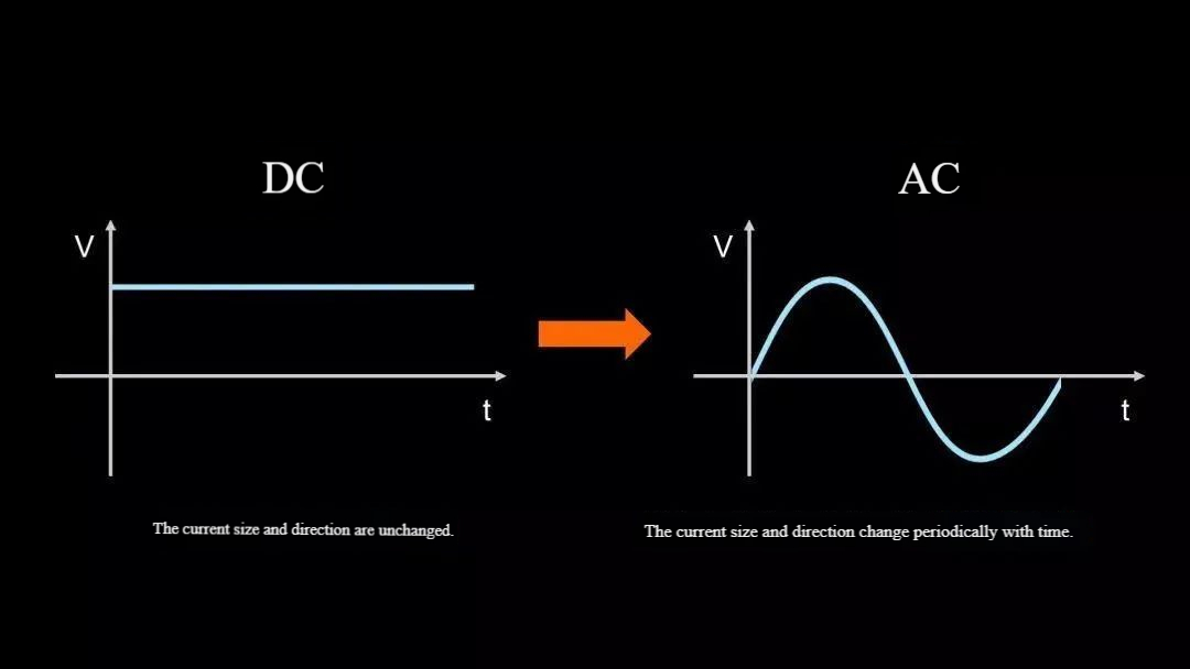
A sine wave can represent the variation pattern of alternating current. A sine wave is a periodically fluctuating waveform with defined maximum values, minimum values, and a fixed period. In alternating current, both the direction and magnitude of the current change periodically over time. This means that, within a complete cycle, the current direction changes twice: from positive to negative, then from negative to positive.
Characteristics of Alternating Current
Low transmission losses: As alternating current can be transmitted at extremely high voltages following step-up through transformers, this substantially reduces the current. According to the formula $P_{loss} = I^2 R$, this significantly minimises energy losses. This enables long-distance power transmission, enhancing the economic efficiency and reliability of power systems.
Low manufacturing costs for power generation and transformers: The alternators feature simple structures and lower manufacturing costs. Compared to complex DC-DC conversion equipment, AC transformers are structurally simpler, lower in cost, lighter in weight, and offer higher efficiency.
High adaptability: AC voltage can be adjusted by transformers to meet diverse equipment requirements. Furthermore, AC can be converted to DC by using rectifiers to satisfy DC power needs.
In summary, AC is a vital power source widely used in electrical systems. However, its use also necessitates the observance of safety precautions and the proper use of equipment, such as rectifiers, to meet diverse power requirements.
What are AC Converters?
The voltage supplied to residential buildings is 100V or 200V. However, most electrical appliances we use operate on DC voltage at 5V or 3.3V. This means that if the AC voltage is not converted to DC voltage, the appliances cannot function. At this time, the AC converter needs to come into play.
An AC converter is an electronic device that transforms alternating current (AC) into direct current (DC). Its applications are extensive, including electronic devices requiring DC power, household appliances, lighting systems, and electric vehicles.
Rectifier Topologies
The most crucial rectifier topologies are half-wave, full-wave (center-tapped transformer), and full-wave bridge (Graetz bridge). The half-wave rectifier is the simplest, only requiring a diode and a load. Figure 1 illustrates this circuit, which includes the following components:
- 50 Hz sine wave generator with 230 VAC (RMS) output voltage
- Voltage transformer stepping down from 230 VAC (RMS) to 195 VAC (RMS)
- Rectifier diode, in this case a SiC Schottky type rated at 650 V, 4 A, and 9 W in the worst-case scenario.
- A 50-ohm resistive load.
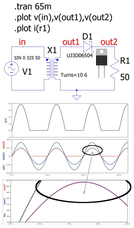
The first waveform above shows the current flowing through the load, which is identical to the current through the diode. The second waveform displays the traces of the input voltage (Vin), the sine-wave output voltage before the diode (Vout1), and the rectified voltage after the Rectifier Diode (Vout2). Thus, the average output voltage of the circuit is not zero. The issue with this circuit is low efficiency, and results in significant ripple. As shown in the waveform below, a slight voltage difference exists between the voltage before the diode and that after it. This is caused by the "forward voltage" parameter, which, for the diodes used, can range from 1.5 V to 2.25 V depending on operating conditions. Since DIODES are not ideal components, this potential difference prevents the peak from being reached. In this configuration, the load receives no power during half of the signal cycle, resulting in the loss of half the valuable signal cycle. In this type of circuit, the diode's operation is critical because it is subjected to high-current peaks during each signal cycle. To reduce the ripple factor, an LC filter can be employed.
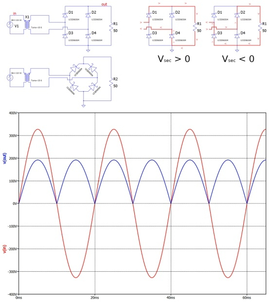
Another rectifier solution is the Graetz bridge, shown in the figure along with its fundamental waveforms: the input (Vin) and output (Vout) traces. To understand the bridge's operation, examine the AC voltage of the sinusoidal input signal and observe its algebraic sign. If the voltage is positive, diodes D1 and D4 conduct while D2 and D3 are off. Conversely, when the voltage is negative, diodes D2 and D3 conduct while D1 and D4 are cutoff. In either case, the current flowing through the load always points in the same direction. This configuration can also be used for continuous power supplies. Regardless of the input current's direction and magnitude, the output voltage maintains the same polarity, making it comparable to preliminary polarity protection circuits. The diagram illustrates two equivalent electrical representations of the bridge. In power applications, connecting two current-conducting diodes in series can dissipate significant power due to the relatively high voltage drop across them. In this configuration, the output signal frequency is twice that of the input signal.
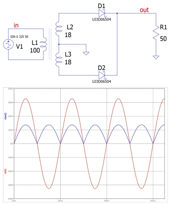
Using a rectifier with a center-tapped transformer allows the same effect as the Graetz bridge and reduces potentially high dissipation.
Furthermore, in this case, its operation is dual, depending on whether the input signal is a positive half-wave or a negative half-wave. If the induced voltage is positive, diode D1 conducts while D2 is cutoff. However, if the induced voltage is negative, diode D1 is cut off while D2 conducts. This circuit is fully equivalent to a full-wave rectifier of the input signal. Since only one diode operates at a time, there are no particular dissipation issues, and this solution is suitable for high-power applications.
From Pulsating Voltage to DC Voltage
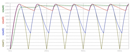
The output voltage must be completely stable, free of ripple and harmonics, and without pulsation.This objective is achieved by employing large-capacity capacitors with filtering capabilities. The rectifier seen earlier enables us to generate a non-zero-average waveform starting from a zero-average voltage. For most devices, the system operates with a positive DC voltage relative to a reference ground. Thus, it is necessary to extract the DC component from the rectified signal. Therefore, a filter circuit must be employed at the rectifier output to stabilize and raise the load voltage as much as possible. One of the most important solutions is the RC filter. A new complication arises when the load exhibits low impedance, as it absorbs most of the current. Consequently, because the signal is sinusoidal, the smoothing capacitor's task is to maintain a stable load voltage duiring the non-conductive period between rectifying pulsess. This configuration performs exceptionally well when the time constant t = RC is significantly larger than the signal ripple's characteristic time. The voltage across the capacitor reaches its maximum, and as the diode enters the blocking state, the capacitor gradually discharges to the load in an exponential manner. This cycle repeats continuously. A similar RC filter consists of a large-capacity electrolytic capacitor connected in parallel with the load. Beyond ensuring continuous positive voltage, designers must minimize or eliminate ripple signals, whose extent depends on signal frequency, filter capacitor values, and load voltage. Typically, the load voltage carries traces of the AC supply voltage superimposed on the DC voltage. This ripple exhibits a sawtooth pattern at twice the input frequency, caused by current absorbed by the load. The capacitor value depends on the maximum ripple percentage the designer can tolerate. Low or no ripple is characteristic of high-quality power supplies. Figure 4 illustrates various signals on the load affected by ripple percentage, depending on the capacitance of the electrolytic capacitor, as shown below:
- v(out1): Signal on the load without any filter capacitors
- v(out2): Signal on the load with a 100 μF filter capacitor
- v(out3): Signal on the load with a 1000 μF filter capacitor
- v(out4): Signal on the load with a 10,000 μF filter capacitor.
It can be observed that the larger the capacitance, the longer the time required for transient equilibrium. To achieve a reasonably acceptable signal in this circuit, an electrolytic capacitor with a capacity of at least 100,000 μF must be used. Regarding the size of the filter capacitor, numerous equations can help designers achieve optimal results. An ideal filter returns only a continuous signal with a ripple factor of zero, thereby eliminating any AC component. Theoretically, designers would require an extremely high-value electrolytic capacitor to ensure slow discharge, time-invariant output voltage, and minimal ripple. However, in practice, significantly increasing filter capacitance offers no particular benefit while increasing the overall size and cost of the fuel system. Furthermore, increasing the capacitor value also increases peak current, potentially damaging the dielectric material of components, placing significant stress on diodes, and causing the entire system to overheat.
What is DC?
What is Direct Current?
Direct current (DC) is the unidirectional flow or movement of electric charge, typically electrons. Current Density varies over time, but its direction of movement remains constant throughout. As an adjective, DC can be used to describe Reference Voltage (whose polarity never changes).
In direct current circuits, electrons are emitted from the cathode (negative electrode, negative magnetic pole) and move toward the anode (positive electrode, positive magnetic pole). However, physicists define direct current as the flow of charge from positive to negative.
Direct current (DC) is generated by electrochemical and photovoltaic cells and batteries. Conversely, in most countries, the current flowing from devices is alternating current (AC). AC can be converted to DC using a power supply consisting of a converter, a rectifier (which prevents reverse current flow), and a filter (which smooths out the pulsations in the current output by the rectifier).
Virtually all electronic and computer hardware requires DC power to function. Most solid-state devices require voltages between 1.5 and 13.5 volts. Current demands span from near zero in electronic watches to over 100 amperes for wireless communication power amplifiers. Devices using vacuum tubes, such as high-power radio or television transmitters and cathode ray tube (CRT) displays, require DC voltages ranging from approximately 150 volts to several thousand volts.
What Are DC Rectifiers?
Within power conversion, different transformation types possess distinct definitions and characteristics. AC-DC conversion is the process of converting alternating current to direct current, also known as rectification. The device performing this function is the DC rectifier.
The rectifier's operating principle is based on the unidirectional conductivity of electronic components. The entire process can be broken down into several key steps, with the core component being the diode. Think of it as an electrical "one-way valve" or "check valve." It allows current to flow only from the positive terminal (anode) to the negative terminal (cathode), while almost completely blocking reverse current.
Key Steps and Circuit Topology
Transformation: Using a transformer to step down high-voltage AC power from the grid (e.g., 220V) to low-voltage AC suitable for electronic devices (e.g., 12V). This is not rectification itself, but rather a typical preliminary step.
Rectification: Utilizes the unidirectional conductivity of diodes to "flatten" the AC waveform. Two primary circuit configurations exist:
- Half-wave Rectification
During the positive half-cycle of the input AC, the diode is forward-biased and conducts, allowing current flow and delivering voltage to the load. During the negative half-cycle, the diode is reverse-biased and blocks current flow, resulting in zero current and no voltage across the load.
- Full-wave rectification
The most common configuration is the bridge rectifier circuit, composed of four diodes. Regardless of whether the input is the positive or negative half-cycle, the current flowing through the load maintains a consistent direction. The output is a continuous, unidirectional pulsed wave. Efficiency is doubled compared to half-wave rectification, and the waveform is smoother. This is currently the most mainstream rectification solution.
Filtering: The voltage after rectification remains pulsating, resembling peaks rather than a smooth, straight line. This is known as pulsating direct current.
Voltage Regulation: Even after filtering, the voltage may still fluctuate slightly due to variations in the input AC voltage or changes in the load current.
Why Perform AC-DC Conversion?
The fundamental role of DC rectifiers lies in addressing the inherent differences between the generation, transmission, and utilization of electrical energy:
- Meeting Electronic Device Requirements: Nearly all modern electronic devices—computers, smartphones, televisions, LED lights, etc.—require DC power for their internal chips, transistors, and integrated circuits to function correctly. Rectifiers are essential for supplying this "fuel."
- Leveraging AC transmission advantages: AC power offers significant benefits for long-distance transmission. Transformers can easily and efficiently step up voltage, substantially reducing energy losses during transmission. This is why power grid companies use high-voltage AC at hundreds of thousands of volts for transmission. Rectifiers enable us to enjoy the convenience of AC transmission while ultimately powering devices with DC.
- Achieving stable and controllable power: Through rectification, filtering, and voltage regulation, high-quality, stable, and reliable DC power is delivered to equipment, preventing voltage fluctuations from damaging precision components.
How to convert AC to DC?
Principles of AC-to-DC Conversion
The process of converting AC to DC is primarily achieved through rectification. Details are as follows:
Half-Wave Rectification
- Working Principle: Utilizing the unidirectional conductivity of diodes, only one half-cycle of the AC waveform (either the positive or negative half-cycle) is permitted to pass through. This converts AC into a pulsating DC that flows in a single direction.For example, in a simple half-wave rectifier circuit, the diode conducts and current passes through the load during the positive half-cycle of the alternating current, while the diode cuts off and no current passes through the load during the negative half-cycle of the alternating current.
- Circuit Composition: Typically consists of a power transformer and a diode. The power transformer steps up the AC voltage to the required level, while the diode performs rectification.
- Output Characteristics: The output DC voltage contains significant ripple, whose magnitude varies with load resistance. The average output voltage is relatively low, typically only about half the AC peak voltage.
Full-Wave Rectification
- Working Principle: Rectifies the entire AC cycle, converting both positive and negative half-cycles into pulsating DC of the same polarity. Common full-wave rectifier circuits include full-wave bridge rectifiers and full-wave controlled rectifiers.
- Circuit Composition: The full-wave bridge rectifier circuit forms a bridge configuration with four diodes. Different diodes conduct during the positive and negative halves of the AC cycle, delivering voltage and current of the same direction to the load. The full-wave thyristor rectifier circuit typically employs controllable devices, such as thyristors. By triggering and controlling the thyristor, it achieves full-wave rectification of AC and allows adjustment of the output DC voltage magnitude.
- Output Characteristics: Compared to half-wave rectification, the output DC voltage exhibits relatively lower ripple content, higher efficiency, and a higher average output voltage—typically around 0.9 times the AC RMS value.
Filtering
- Purpose: The pulsating DC after rectification contains significant AC components (i.e., ripple). Filtering is required to obtain a smoother DC.
- Common Filtering Methods: Capacitive filtering, inductive filtering, and composite filtering. Capacitive filtering uses the charging and discharging of capacitors to reduce ripple. When the rectified voltage rises, the capacitor charges; when the voltage drops, the capacitor discharges, thereby smoothing the voltage. Inductive filtering utilizes the inductive coil's resistance to alternating current and its passage of direct current to filter out ripple, resulting in smoother current flow. Composite filtering combines capacitive and inductive filtering to achieve superior filtering performance.
Voltage Stabilization
Purpose: Due to variations in AC input voltage and load conditions, the filtered DC voltage may fluctuate. Voltage regulation is necessary to provide stable DC power to electronic equipment.
Common Stabilization Methods: Linear regulation and switching regulation. Linear regulator circuits stabilize output voltage through the linear amplification of active components like transistors. Their advantages include low output ripple and high stability, but efficiency is relatively low. Switching regulator circuits adjust the output voltage by controlling the on and off times of switching devices, such as transistors. Their advantage is high efficiency, but the output ripple is relatively large, requiring further Filtering.
AC-to-DC Circuit Design
Here, the capacitor voltage-reduction method is used as an example.
The capacitor voltage-reduction method uses the capacitive reactance of a capacitor at a specific AC signal frequency, along with the AC version of Ohm's law, to limit the maximum operating current.
Example: AC voltage 220V, power frequency 50Hz, capacitance 1μF;
Reactive resistance generated by the capacitor: Rc = 1/(2πfc) = 3180
Current: I = U / Rc = 70 A
If the capacitor is ideal, no power is dissipated across it. The current flowing through it is purely reactive, so power dissipation depends on the subsequent circuit.
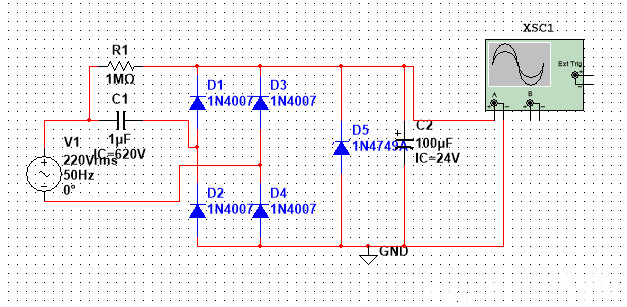
AC 220V to DC 24V (Capacitor Voltage Reduction Method) First Method:
Circuit Diagram:
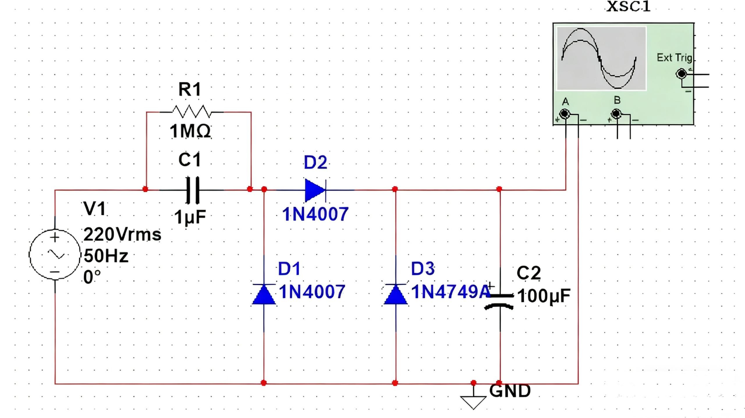
C1 is the step-down capacitor.
R1 is the discharge resistor for C1 after power shutdown (prevents electric shock from residual capacitor charge; typically 820K-1M).
D2 is a half-wave rectifier diode.
D1 provides a discharge path for C1 during the negative half-cycle of the mains voltage.
D3 is a Zener diode.
C2 is the filter capacitor (100uF is sufficient, as this circuit does not carry high currents).
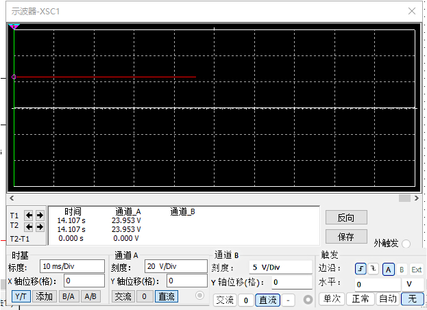
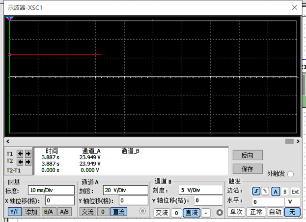
Oscilloscope test output voltage:
AC 220V to DC 24V (Capacitor Voltage Reduction Method) Method 2:
Circuit diagram:
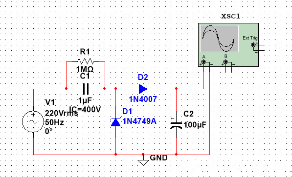
C1 is the voltage-reducing capacitor.
R1 is the discharge resistor for C1 after power shutdown (prevents electric shock from residual capacitor charge; typically 820K-1M).
D1 is the Zener diode.
D2 is the half-wave rectifier diode.
C2 is the filter capacitor (100uF is sufficient, as this circuit does not carry high currents).
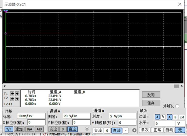
Oscilloscope test output voltage:
AC 220V to DC 24V (capacitor voltage reduction method) Third method:
Circuit diagram:
C1 is the voltage-reducing capacitor.
R1 is the discharge resistor for C1 after power shutdown (prevents electric shock from residual capacitor charge; typically 820K-1M).
D1~D4 are half-wave rectifier diodes (forming a bridge rectifier circuit);
D5 is the Zener diode.
C2 is the filter capacitor (100uF is sufficient, as this circuit does not carry high currents).
Oscilloscope output voltage measurement:
What equipment converts AC to DC?
Classification by Technical Principle
This is the most fundamental classification method, primarily divided into two categories: linear power supplies and switching power supplies.
(1) Linear Power Supply
Working Principle:
- Transformer: First, a mains transformer (the heavy, large iron block) directly steps down the utility voltage (e.g., 220V AC) to a lower AC voltage.
- Rectification: An AC-to-DC conversion is performed using a diode-bridge rectifier, producing a pulsating DC output.
- Filtering: Large capacitors smooth the voltage to eliminate ripples.
- Voltage Regulation: A linear voltage regulator IC (e.g., L7805) or transistor circuit outputs a highly stable DC voltage with minimal ripple. Linear regulators operate by "consuming" their excess voltage (similar to using a variable resistor for voltage division).
Features:
- Advantages: Simple circuitry, low output ripple, minimal electromagnetic interference, and high reliability.
- Disadvantages: Low efficiency (typically 30%-60%), bulky and heavy (due to the use of a mains-frequency transformer), significant heat generation, and a narrow input voltage range.
(2) Switching Power Supply
This is the dominant power supply technology today.
Working Principle:
- Rectification and Filtering: First, mains power (220V AC) is directly converted into high-voltage DC (approximately 300V DC) via a rectifier bridge and a capacitor.
- Switching Inverter: This is the core step. A high-frequency switching device (such as a mosfet) "chops" this high-voltage DC into a high-frequency AC square wave at tens of thousands to millions of times per second.
- Transformation: A high-frequency transformer steps down the high-frequency square-wave voltage to the desired output level. Due to the high frequency, the transformer can be made extremely compact and lightweight.
- Output Rectification and Filtering: Diodes and capacitors rectify and filter the stepped-down high-frequency AC square wave into a smooth DC output.
- Feedback Voltage Regulation: Precisely stabilizes the output voltage by controlling the on-off timing of the switching transistors (i.e., PWM pulse width modulation) through a complex feedback circuit.
Features:
- Advantages: Extremely high efficiency (typically 80%-95%), compact size and lightweight, wide input voltage range (usually universal 100-240V), low heat generation.
- Disadvantages: Complex circuitry, high-frequency ripple in output, potential for electromagnetic interference.
Classification by Appearance and Application
Based on these two technologies, the devices we encounter daily come in various forms.
- Power Adapter
This is the most familiar AC-DC device, typically a compact standalone box that plugs into a wall outlet on one end and connects to equipment via a DC output cable on the other.
Technology: Most are modern switching power supplies.
Examples: Laptop power adapters, mobile phone chargers, router power supplies, surveillance camera power supplies.
- Built-in Power Supply
AC-DC conversion circuitry is integrated directly within the device.
Examples: ATX power supply (switching power supply) inside desktop computer towers. TVs and DVD players often feature a dedicated power board (switching power supply) near the main circuit board. Older radios contained transformers and rectifier circuits (linear power supply).
- Industrial/Communication Power Supplies
Equipment providing high-power, high-reliability DC power for industrial machinery, base stations, server rooms, etc. Typically features redundancy design, power factor correction, and other functions.
Technology: Switching power supply.
Examples: DC power modules in server racks, high-power rectifier cabinets for electroplating/electrolysis.
- Charging Stations
AC Charging Station (Slow Charge): Essentially a safety connector and control unit; the actual AC-DC conversion occurs within the vehicle's onboard charger.
DC charging stations (fast charging): These are large, powerful AC-DC rectifiers that directly convert grid AC power into DC power for charging vehicle batteries. Consequently, they are both high-power and bulky.
- Uninterruptible Power Supply (UPS)
A UPS contains AC-DC rectifier/charging circuits to charge its internal batteries, along with dc-ac inverter circuits that convert battery DC power to AC power for equipment during power outages.
|
Equipment Types |
Key Technology |
Features |
Common Applications |
|
Linear Power Supply |
Linear Voltage Regulator |
Heavy, large, low efficiency, clean output, minimal interference |
Laboratory instruments, high-fidelity audio systems |
|
Switching Power Supply |
Switching Regulator |
Lightweight, compact, high efficiency, ripple present, high interference |
Absolute mainstream: chargers, computers, televisions, and nearly all electronic devices |
|
Power adapters |
Mostly switch-mode power supplies |
External, portable, standardized |
Laptops, smartphones, routers |
|
Built-in power supply |
Mostly switching power supplies |
Integrated within the device, an all-in-one design |
Desktop computers (ATX), televisions, and audio systems |
|
Industrial power supplies |
Switching power supply |
High power, high reliability, redundant |
Servers, communication base stations, and industrial control systems |
|
Electric vehicle chargers |
Switching Power Supply |
Extremely high power, technologically advanced |
DC charging stations, onboard chargers (OBC) |
Direct Current to Alternating Current Conversion
Basic Principle of DC to AC Conversion
This is the schematic diagram of DC-to-AC conversion.
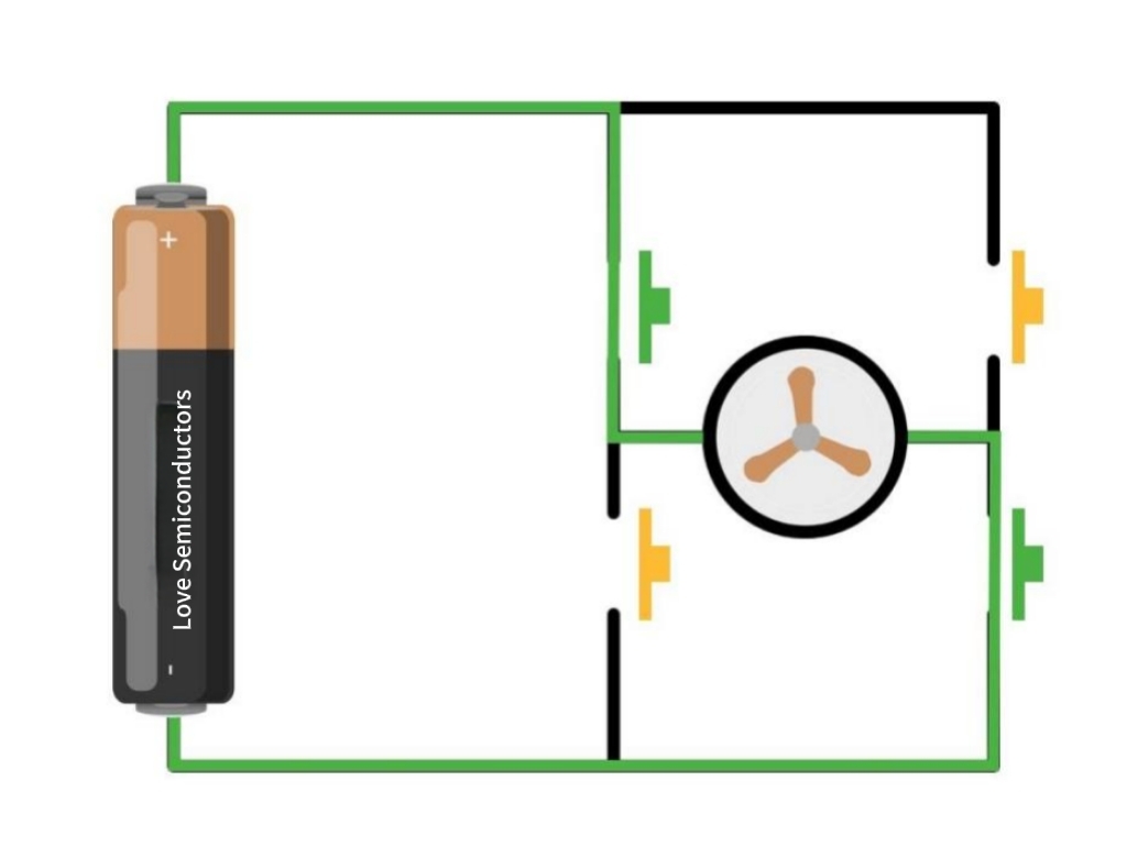
When the green switch is pressed, the current flows in this direction, producing this waveform;
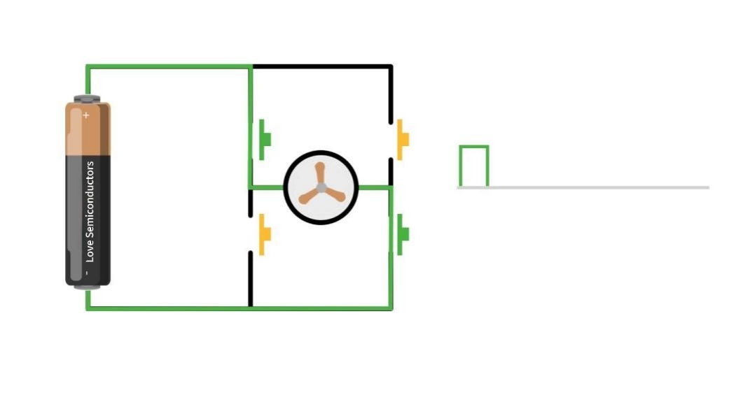
When the yellow switch is pressed, the current flows in this direction, producing a waveform with the opposite polarity.
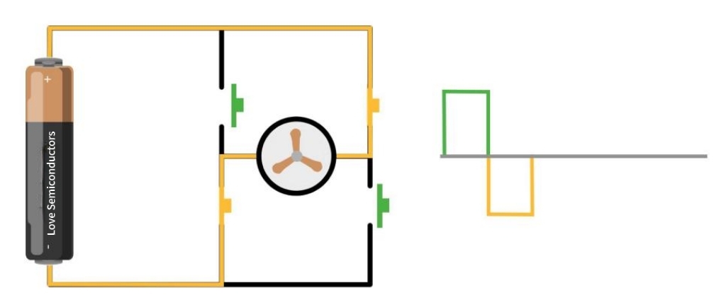
By repeatedly switching the circuit, DC is converted into AC. However, this is a square-wave AC signal, which cannot drive capacitive or inductive loads. Its waveform is not smooth, with voltage undergoing abrupt changes that severely shorten the lifespan of electrical appliances.
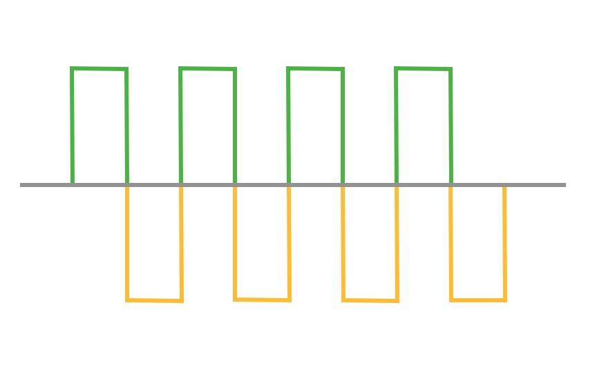
Therefore, the square wave AC must be converted into sinusoidal AC. The conversion method involves increasing the switching frequency. Notice how the average value now approaches that of sinusoidal AC?
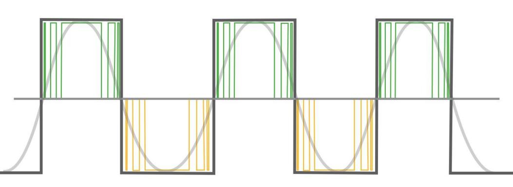
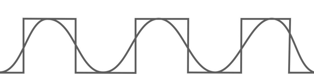
Finally, we need to smooth the waveform. A simple method is to add capacitors. Capacitors act like reservoirs, storing intermittent current and releasing it steadily. This converts the square-wave AC into a sine-wave AC.
Finally, who controls the switching? The answer is a chip. We program the switching sequence into the chip, enabling it to generate the intended switching signals. The chip controls electronic switches like power MOSFETs or IGBTs, as these transistors respond to electronic signals and can switch tens of thousands of times per second.
How DC Converters Work
A DC-DC converter is an electronic device or circuit that transforms one direct current (DC) voltage into another DC voltage. More specifically, it can adjust the DC voltage level (step-up, step-down, or both) and typically provides a regulated (stable) output.
For better understanding, we can compare it with the previously discussed AC-DC rectifier:
- AC-DC Rectifier: Input is AC, output is DC. For example, converting 220V AC from a wall outlet to 5V DC for charging a mobile phone.
- DC-DC Converter: Input is DC, output is also DC, but the voltage or current characteristics change. For example, converting 12V DC from a car battery to 5V DC for charging a phone, or boosting 3.7V DC from a lithium battery to 12V DC for driving LED lights.
Core Principle: How Does It Work?
Unlike transformers that directly alter DC voltage (DC cannot be stepped up/down by conventional transformers), the core principle of DC-DC converters is "inverting first, then rectifying."
The basic workflow can be summarized in four steps:
- Switching (Inversion): Using semiconductor switches (such as MOSFETs), the input DC voltage is rapidly switched on and off at an extremely high frequency (ranging from tens of kHz to several MHz). This process effectively "chops" the constant DC voltage into a series of pulses or square waves. This essentially transforms the DC voltage into a form of "AC" (strictly speaking, pulsed DC).
- Transformation (Optional): These high-frequency pulses transfer and convert energy through energy storage components (typically inductors and capacitors, sometimes high-frequency transformers). Inductors and capacitors function as "temporary reservoirs" and "energy carriers" during this stage.
- Rectification: The transformed high-frequency pulses are rectified back into DC through diodes or synchronous switches.
- Filtering: Finally, the output DC is smoothed and filtered using components such as capacitors to produce a clean, stable DC voltage.
By precisely controlling the on-off time ratio (i.e., duty cycle) of the switches, the average output voltage can be accurately regulated to achieve step-down, step-up, or even reverse voltage functionality.
Main Types and Functions
Based on functionality, DC-DC converters are primarily categorized as follows:
- Buck Converter
Function: Reduces the input voltage to the desired output voltage. The output voltage is lower than the input voltage.
Formula: Vout = D * Vin (where D is the duty cycle, 0 < D < 1)
Typical Application:
Converts the 12V voltage from the computer motherboard into the 1.2V, 3.3V, and 5V voltages required by the CPU, memory, and other components.
Converts the 5V voltage from USB ports to the 3.3V or 1.8V operating voltage required by chip cores.
In mobile phones, the converter converts the battery voltage (approximately 3.7V) to lower voltages required by various modules.
- Boost Converter
Function: Elevates the input voltage to the required output voltage. The output voltage is higher than the input voltage.
Formula: Vout = Vin / (1 - D)
Typical Applications:
LED Flashlight: Boosts the voltage from a single 1.5V battery to over 3V required to drive a white LED.
USB OTG: Boosts the 3.7V voltage from a phone battery to 5V to power other peripherals (e.g., USB flash drives).
Car jump starters: Boost the voltage from a lithium battery pack to the higher voltage required to start a vehicle.
- Buck-Boost Converter
Function: Capable of both step-down and step-up conversion. It delivers a stable, preset output voltage regardless of whether the input voltage is higher, lower, or equal to the output voltage.
Typical Applications:
Lithium-Battery-Powered Devices: Lithium batteries typically operate between 3V and 4.2V, while many circuits require a stable 3.3V. When the battery voltage exceeds 3.3V, the converter operates in buck mode; when the voltage drops below 3.3V, it switches to boost mode to maintain 3.3V.
- Isolated Converters
Function: Incorporating a high-frequency transformer into any of the above topologies achieves electrical isolation between the input and output sides. This means there is no direct electrical connection between the input and output, enhancing safety and immunity to interference.
Typical Applications:
Communication interfaces in industrial equipment (e.g., RS-485, CAN bus).
Medical devices that ensure patient isolation from high-voltage power grids.
Secondary-side circuits within chargers.
When Do You Need to Convert AC to DC Power?
Converting alternating current (AC) to direct current (DC) is one of the most fundamental and widespread operations in modern power electronics. Its necessity stems from a fundamental mismatch between how electrical energy is generated, transmitted, and ultimately utilized.
Simply put, nearly all electronic devices powered by wall outlets (AC) require DC power for their core internal circuits to function. Therefore, AC-DC conversion is essential whenever powering such equipment.
Furthermore, understanding when to convert alternating current to direct current is crucial for optimizing energy efficiency and saving energy.The following outlines key scenarios requiring AC-to-DC conversion, categorized into several critical aspects for understanding:
Powering the Vast Majority of Electronic Devices
This is the most common scenario encountered in daily life. Virtually all complex electronic devices and semiconductor components must operate on direct current.
The physical operation of electronic components such as transistors, integrated circuits (chips), microprocessor units, and memory relies on voltage and current flowing in a constant direction (DC) to represent logical states of "0" and "1" and to maintain stable operating points. The constantly changing direction of AC prevents them from functioning correctly and can even cause damage.
Typical Devices:
Computers and Communication Equipment: Desktop computers, laptops, servers, routers, switches.
Consumer Electronics: Smartphones, tablets, televisions, audio systems, gaming consoles.
Home Appliances: Modern refrigerators, air conditioners, microwave ovens (whose internal control boards require DC power).
LED lighting: LED bulbs are DC devices, and their drivers convert AC to DC.
In all these devices, you'll find a "power adapter" or internal power module designed explicitly for AC-DC conversion.
Battery Charging and Applications
Batteries are purely DC power devices. Therefore, all battery-related charging and application scenarios require AC-DC conversion.
Reason: The grid supplies AC power, while the battery charging process is a DC electrochemical reaction.
Typical scenarios:
Various chargers: Smartphone chargers, laptop chargers, power tool chargers, drone chargers, etc. These convert AC power from wall sockets into DC voltage and current suitable for batteries.
Uninterruptible Power Supplies (UPS): During normal grid operation, a UPS charges its internal battery via an AC-DC rectifier circuit. During power outages, it utilizes the stored DC power from the battery, converting it back to AC via an inverter to supply connected devices.
Electric Vehicles: At slow-charging stations, the onboard charger converts AC to DC to charge the power battery. Fast-charging stations function as large, high-power AC-DC rectifiers that directly supply high-voltage DC to the vehicle battery.
Industrial and Power System Applications
In industrial applications, DC power is widely adopted due to its superior controllability.
DC motors offer superior speed regulation (achieved smoothly by adjusting voltage) and substantial starting torque. Additionally, processes such as electrolysis and electroplating require a constant DC power supply.
Typical Applications:
Motor drives: DC motors used in cranes, elevators, rolling mills, and similar equipment.
Electrochemical Industry: Electrolytic smelting of metals like aluminum and copper, as well as surface treatment processes including electroplating and anodizing.
High-voltage direct current transmission: For ultra-long-distance power transmission, alternating current is rectified into high-voltage direct current for transmission, then converted back to alternating current at the receiving end. This reduces transmission losses, enhancing efficiency and economic viability.
Renewable Energy Systems
Generation and consumption in renewable energy systems, such as solar and wind power, are mismatched.
Reasons:
Solar Energy: Solar panels generate direct current (DC).
Wind Energy: While wind turbines output alternating current (AC), their frequency and voltage are unstable.
Typical Systems:
Photovoltaic (PV) System: DC electricity generated by solar panels is converted to AC via an inverter for grid connection or household use. In off-grid systems, DC can be stored directly in batteries (DC-DC) or used via an inverter.
Wind Power Systems: Typically, the variable-frequency AC generated by the turbine is first rectified into DC, then converted by an inverter into stable, grid-synchronized AC. This process achieves AC-→DC-→AC conversion.
Whenever the end-user of electrical energy is an electronic circuit, chip, or battery, and the source is AC from the grid, conversion from AC to DC is required. This serves as the technical bridge connecting our AC grid world to the internal DC world of electronics.
Common Types of AC to DC Converters
Different types of AC to DC converters (or DC rectifiers) include half-wave rectifiers, full-wave rectifiers, bridge rectifiers, controllable rectifiers, and switching power supplies.
Half-Wave Rectifier
This is the simplest rectifier circuit, using only a single diode. It allows only half of the AC input waveform to pass through, while the other half is completely suppressed.
Operating Mechanism:
Positive Half-Cycle: When the AC input is in its positive half-cycle, the diode is forward-biased and conducts. Current flows through the diode and load resistor, producing an output voltage across the load.
Negative Half-Cycle: During the negative half-cycle of the AC input, the diode is reverse-biased and turns off. No current flows through the circuit, and the output voltage across the load is zero.
Output Waveform: A series of spaced sine pulses with the same frequency as the input AC. The average value (DC component) of the output voltage is very low.
Half-wave rectification is the most primitive form of AC-DC conversion. Its output is a highly pulsating DC voltage, virtually unsuitable for directly powering any electronic device. It must undergo subsequent Filtering and voltage regulation to become smooth. Its efficiency is extremely low, only 40.5%, and is therefore used only in a very limited number of simple circuits with extreme cost and size constraints (such as electric shavers).
Full-Wave Rectifier
A full-wave rectifier utilizes a center-tapped transformer and two diodes to use both the positive and negative halves of the AC waveform, allowing current to flow in the same direction through the load.
Operating Mechanism:
Positive Half-Cycle: Assuming the top terminal of the transformer is positive. Current path: Top terminal → D1 → Load → Center Tap.
Negative Half-Cycle: The bottom terminal of the transformer is now positive. Current path: Bottom terminal → D2 → Load → Center tap.
Regardless of the half-cycle, the direction of current flowing through the load remains consistent.
Output Waveform: Continuous, unidirectional sinusoidal pulses with a frequency twice that of the input AC. Its DC component is twice as high as that of half-wave rectification.
Full-wave rectification offers significantly higher efficiency (approximately 81%) and better ripple performance than half-wave rectification. However, its drawback is the requirement for a specialized center-tapped transformer, which is bulky and costly. Its output is also pulsating DC, necessitating Filtering for practical use.
Bridge Rectifier
This is the most common and practical full-wave rectification solution. It employs four diodes connected in a bridge configuration to achieve full-wave rectification without requiring a center-tapped transformer.
Operating Mechanism:
Positive Half-Cycle: Current path: AC+ → D1 → Load → D3 → AC-.
Negative Half-Cycle: Current path: AC- → D2 → Load → D4 → AC+.
The positive and negative halves form two distinct current paths, but the direction of current flow through the load remains consistent.
Output Waveform: Identical to full-wave rectification, producing continuous pulses at twice the input frequency.
The bridge rectifier is the standard front-end configuration for the vast majority of linear and switching power supplies. It directly converts mains power (e.g., 220V AC) into high-voltage pulsating DC. This high-voltage DC is then fed into subsequent circuits: in linear power supplies, it is filtered by large capacitors before reaching the linear regulator; in switching power supplies, it serves as the "primary rectifier" to supply the high-frequency switching inverter circuit.
Controllable Rectifier
Thyristors replace diodes as rectifying elements. By controlling the thyristor's conduction phase angle, the average value of the output DC voltage can be continuously adjusted.
Working Principle:
A thyristor requires not only a forward voltage but also a trigger pulse (gate signal) to conduct.
By controlling the timing of this trigger pulse within the AC cycle (i.e., controlling the trigger angle α), the start time of thyristor conduction in each half-cycle (i.e., conduction angle θ) can be determined.
The larger the trigger angle α, the smaller the conduction angle θ, and the lower the average output voltage becomes.
Output Waveform: No longer a complete sinusoidal wave, but a waveform with a "truncated segment." By adjusting the trigger angle, the output waveform can be continuously varied from zero to its maximum value.
Controllable rectification achieved a leap from "uncontrollable" to "controllable." It evolved beyond simple conversion into a power control device. Its output remains pulsating DC requiring Filtering, but the average value is precisely controllable. It finds extensive application in fields requiring high-power, adjustable DC power supplies, such as DC motor speed control, battery charging, electroplating, and industrial heating.
Switching Power Supply
This represents the dominant power supply technology in modern electronics. Utilizing high-frequency switching and pulse-width modulation (PWM), it achieves high efficiency, a compact size, and a wide input-voltage range.
Working Principle (Using Flyback Configuration as Example):
AC-DC Rectification and Filtering: The input AC power first passes through a bridge rectifier and a large capacitor, converting it into high-voltage DC. This is the first AC-DC conversion, resulting in coarse high-voltage DC.
High-Frequency Switching and Inversion: A power-switch transistor switches this high-voltage DC on and off at an extremely high frequency, transforming it into a high-frequency AC square wave.
Transformation and Isolation: The high-frequency square wave is stepped down and electrically isolated via a high-frequency transformer.
Secondary Rectification and Filtering: The stepped-down high-frequency square wave is transferred to the transformer secondary, where it is rectified by ultra-fast recovery diodes or synchronous rectification MOSFETs. This step precisely embodies the concept of "DC Rectification": it rectifies a high-frequency AC square wave that was originally inverted from DC. Therefore, this rectification process can be viewed as rectifying the local AC component within a DC-AC-DC conversion chain.
Feedback and Voltage Regulation: The final DC output voltage is stabilized by adjusting the switching transistor's duty cycle via a PWM controller.
In SMPS, rectification occurs at two levels: Primary Rectification: Bridge rectification at the input converts utility-frequency AC to high-voltage DC. Secondary Rectification: Rectification at the output stage converts high-frequency AC into low-voltage DC. This represents the core application scenario for DC rectification. To achieve ultimate efficiency, modern SMPS commonly employ synchronous rectification, replacing diodes with MOSFETs with extremely low on-resistance, further reducing losses in the rectification section.
How to Choose the Right AC to DC Converter
Understanding Core Electrical Parameters
This is the most critical step. You must examine the power requirements label on your device or in its manual, which typically specifies the input requirements. Simultaneously, review the output parameters indicated on the candidate converter.
Three core parameters must match or be compatible:
- Output Voltage: This must precisely match the device's voltage requirement. For example, if the device requires 12V DC, you must select a converter with 12V output. Overvoltage will burn out the device; undervoltage will prevent normal operation or startup.
- Output Current: Must equal or exceed the device requirement. Units are amperes (A) or milliamps (mA). 1000mA = 1A. The converter's current output must be greater than or equal to the device's current demand. For example, if a device requires 12V 1.5A, you can choose a 12V 1.5A, 12V 2A, 12V 3A converter, etc. Always choose a higher current rating rather than a lower one. The device will only draw the current it needs and will not forcefully draw more. However, if you select a converter with a current rating lower than the device's requirement (e.g., using a 1A converter for a 1.5A device), the converter may overheat, become damaged, or cause the device to operate erratically due to overload.
- Power Polarity: This is a characteristic of direct current (DC), categorized as "positive inside, negative outside" or "negative inside, positive outside." The polarity is indicated by a symbol on the adapter's plug. It must perfectly match the polarity required by your device. Reversing the polarity can instantly damage the device.
Determining Interface Type and Size
- Interface Type: Common interfaces include round jacks, USB-A, USB-C, etc. Ensure the converter's plug physically fits your device.
- Interface Size: Circular ports vary in inner diameter (ID) and outer diameter (OD) (in millimeters). Measure your device's port dimensions with calipers or bring the device to the store for comparison. Common sizes include 5.5mm x 2.1mm and 5.5mm x 2.5mm.
- Cable Length: Consider the required power cable length for convenient use.
Consider Adapter Types and Additional Features
Based on your needs and budget, you can choose different converter types:
Traditional Linear Power Supply (Transformer)
Advantages: Simple structure, low output ripple, minimal electromagnetic interference.
Disadvantages: Bulky, heavy, low efficiency, and high heat generation.
Applications: High-fidelity audio equipment sensitive to electromagnetic interference, though now less common.
Switching Power Supply (Most Common Type)
Advantages: Compact size, lightweight, high efficiency, high power output, and low cost.
Disadvantages: May generate high-frequency ripple and electromagnetic interference.
Applications: Suitable for the vast majority of modern electronic devices, such as laptops, monitors, routers, cameras, etc.
Adjustable Voltage Power Supply (Laboratory Power Supply)
Output voltage and current limits can be manually adjusted, suitable for electronics hobbyists, repairs, and experiments.
USB-Powered Converters
Many low-power devices (e.g., smart speakers, Wi-Fi bulbs) now draw power directly from USB ports. You only need a qualified USB charger (which is itself an AC-DC converter) and a data cable.
Note: USB chargers also vary in power rating. Ensure it supports the required voltage and current for your device (including fast-charging protocols like QC or PD).
Prioritize Safety Certifications and Quality
Safety Certifications: Choose products certified by authoritative bodies, such as China's CCC (3C Certification), UL in the US, or the EU's CE mark. These certifications indicate the product meets basic standards for electrical safety, flame resistance, and other critical aspects.
Brand and Craftsmanship: Prioritize reputable brands, which typically offer better quality control and after-sales service. Inspect the power cord for sturdiness, check for tight seams on the casing, and assess the weight in your hand (substandard products are often very light).
Selection of an AC to DC converter focuses on matching the output voltage, current, and interface, as well as considering type differences and safety approvals. Choosing the right AC to DC converter ensures efficient rectification and a stable power supply.
Applications of AC to DC Converters
AC-to-DC converters are ubiquitous in modern technology, serving as the critical bridge between grid AC power and the DC-powered equipment that defines our daily lives and industrial operations. Their wide-ranging applications ensure the proper functioning, efficiency, and safety of electronic systems.
Industrial Automation
- PLCs and Controllers: Programmable logic controllers and industrial computers require stable, clean DC power to execute control logic precisely. Any power fluctuations can cause production errors or system crashes.
- Transducers and Transmitters: Various Transducers and transmitters that monitor temperature, pressure, flow, etc., are typically low-voltage DC devices.
- Motor Drives and Servo Systems: While large motors typically operate on AC power, their internal drives and servo amplifiers convert AC to DC for precise speed and torque control.
- Human-Machine Interfaces: Industrial HMIs and touchscreens rely on stable DC power supplies.
Industrial-grade power supplies typically feature wide operating temperature ranges, conformal coatings for moisture and dust protection, and high immunity to electrical noise and voltage surges.
Communication Devices
- Network switches and routers: All network equipment in data centers, offices, and base stations requires DC power to process and route data packets.
- Servers and Storage Devices: Power supply units inside servers convert AC power from the grid into multiple DC voltages for use by the motherboard, CPU, memory, and hard drives.
- Base Station Equipment: Cellular base stations use high-power AC-to-DC converters to power amplifiers, transceivers, and signal processing units.
- Fiber Optic Network Terminals: Devices like ONUs and ONTs connect fiber-optic internet to homes and businesses.
These power supplies prioritize high efficiency to minimize energy loss and heat generation, as well as high power density to save space in crowded server cabinets. Redundancy and hot-swap capabilities are also common.
Consumer Electronics
External Power Adapters
Laptops: High-power adapters (e.g., 65W).
Smartphones and tablets: USB chargers, now commonly supporting fast-charging protocols.
Smart Home Products: Wireless routers, smart speakers, surveillance cameras, gaming consoles, etc.
Built-in Power Supplies
Televisions: Internal power boards convert AC to DC to supply the screen, backlight, and main logic board.
Desktop computers: The computer power supply is a complex AC-to-DC converter providing multiple voltage outputs.
Audio equipment: Amplifiers, DVD/Blu-ray players, and set-top boxes.
Emphasis on compact size, lightweight design, safety (with certifications like CCC/UL/CE), and cost-effectiveness. Efficiency is also increasingly important due to energy regulations.
Battery Charging and Power Management
- Onboard charger: The onboard charger inside an electric vehicle is an AC-to-DC converter that takes AC power from a charging station or household outlet and converts it to DC to charge the high-voltage battery pack.
- AC Charging Station: Provides AC power to the vehicle, relying on the vehicle's onboard charger for conversion.
- Uninterruptible Power Supply (UPS): Continuously converts AC to DC to charge its internal battery. During grid outages, it inverts stored DC back to AC to power critical loads.
- Portable Device Charging: Charging circuits inside smartphones, laptops, and power banks manage DC power from adapters, safely charging lithium-ion batteries according to specific voltage and current profiles.
- Solar Systems: In grid-connected solar systems, microinverters perform DC-to-AC conversion. However, the system's control and monitoring units, along with battery-based off-grid systems, rely on AC-to-DC converters.
These applications require precise voltage and current control to ensure safe, efficient battery charging, maximizing battery lifespan and performance. High efficiency is critical for minimizing energy loss during charging.
Efficiency of AC to DC Converters
The Importance of AC-to-DC Conversion Efficiency
- Energy Savings and Reduced Operating Costs: Lower efficiency means more electrical energy is wasted as heat during conversion. For equipment that operates continuously year-round (e.g., data center servers, communication base stations), a 1% improvement in efficiency yields significant savings in electricity costs.
- Thermal Management and Size Reduction: The substantial heat generated by low efficiency necessitates complex cooling systems (e.g., large heat sinks and fans) for dissipation, thereby increasing product size, weight, and cost. High-efficiency converters produce less heat, enabling more compact designs and enhancing system reliability.
- Environmental Sustainability: Reducing energy waste minimizes carbon emissions from power generation, aligning with global green energy and environmental regulations.
- Enhanced System Reliability and Lifespan: Heat is the primary threat to electronic components. Lower operating temperatures significantly extend the lifespan of critical components like electrolytic capacitors and power semiconductors, thereby increasing the system's mean time between failures.
Key Factors Affecting Efficiency
Topology
Different circuit topologies inherently possess varying efficiency potentials. For example, flyback converters are commonly used for medium- to low-power applications, achieving efficiencies of 85%-90%; whereas LLC resonant converters are employed for higher-power applications, achieving efficiencies exceeding 95%.
Component Selection
Power Switching Devices: MOSFET on-resistance and switching losses are the primary sources of loss. Using MOSFETs or GaN (Gallium Nitride) devices with lower Rds(on) and faster switching characteristics can significantly improve efficiency.
Magnetic Components: Iron losses and copper losses in transformers. Using low-loss core materials and thicker windings can reduce losses.
Rectifier Diodes: Forward voltage drops in conventional silicon diodes cause losses. Replacing diodes with low Rds(on) MOSFETs using synchronous rectification is a key efficiency-enhancing technique.
Load Conditions
Efficiency varies with output load. Peak efficiency is typically achieved at 50%-75% of rated load, with efficiency decreasing at light load and full load. Therefore, selecting a power-matched converter is critical.
Input Voltage
For converters with wide input voltage ranges (e.g., 85-264V AC), efficiency also varies with input voltage. Generally, efficiency is slightly higher at higher input voltages.
Practical Considerations for High-Efficiency Converter Design
Selecting the Appropriate Topology
Select the most suitable topology based on power rating, cost targets, and performance requirements. For example, the LLC resonant topology is preferred for applications >200W due to its extremely low switching losses.
Adopting Advanced Semiconductor Technologies
Utilize GaN and SiC: Gallium nitride and silicon carbide wide-bandgap semiconductor devices offer faster switching speeds, lower on-resistance, and superior high-temperature performance, enabling ultra-high efficiency (>96%).
Comprehensive adoption of synchronous rectification: Replacing diodes with MOSFETs on the secondary side delivers exceptionally efficient gains, particularly in low-voltage, high-current output scenarios.
Optimizing Magnetic Component Design
Employ low-loss core materials such as PC95.
Optimize winding structures by using Litz wire or multi-strand twisted wire to reduce skin effect losses at high frequencies.
Implementing Soft Switching Technology
Employ ZVS (Zero Voltage Switching) and ZCS (Zero Current Switching) techniques to activate or deactivate power switches when voltage or current reaches zero, thereby fundamentally eliminating switching losses. The LLC topology inherently functions as a ZVS circuit.
Control Standby Power Consumption
In light-load or standby modes, employ control strategies such as cycle skipping and reduced switching frequencies to minimize static power consumption and meet stringent energy-efficiency standards.
FAQ
When do you need to convert AC to DC power?
- To meet the operational requirements of electronic devices: Virtually all modern electronics—computers, smartphones, televisions, LED lights, etc.—require DC power for their internal chips, transistors, and integrated circuits to function correctly. Rectifiers are essential components that provide this "fuel" to the devices.
- Leveraging AC transmission advantages: AC power offers significant benefits for long-distance transmission. Transformers efficiently step up voltage, substantially reducing energy loss during transmission. This is why power grids use high-voltage AC (hundreds of thousands of volts) for transmission. Rectifiers enable us to harness the convenience of AC transmission while ultimately powering devices with DC.
- Achieving stable and controllable power: Through rectification followed by filtering and voltage regulation, high-quality, stable, and reliable DC power is delivered to devices, preventing voltage fluctuations from damaging precision components.
What is an AC to DC converter called?
An AC-to-DC converter is an electronic device or circuit that transforms alternating current into direct current. It is commonly referred to as a rectifier in electronics.
A basic AC-DC converter (rectifier) typically involves one or more key steps:
- Transformer: Adjusts the AC voltage to an appropriate level (optional; in some designs, this is handled by other circuits).
- Rectification: This core step uses diode unidirectional conductivity to convert bidirectional AC to unidirectional pulsating DC.
- Filtering: Uses components such as capacitors to smooth the pulsating rectified DC, reducing fluctuations and producing a more stable DC output.
- Voltage Regulation: Ensures the output DC voltage remains stable at a precise value, unaffected by input voltage or load variations (achieved in more complex switching power supplies).
How efficient are AC to DC converters?
The efficiency of AC-DC converters varies significantly depending on design, power rating, and technology. Generally:
- Older or low-quality designs: Efficiency may fall below 70%, resulting in substantial energy waste as heat.
- Standard modern switching power supplies: Efficiency typically ranges between 80% and 90%. This is a common level.
- High-efficiency/high-quality designs: Efficiency can reach 90%–95%.
- Top-tier products using cutting-edge technologies (e.g., GaN): Efficiency can exceed 96% or higher.
The primary reason for low efficiency is energy loss as heat during conversion. These losses mainly stem from:
- Switching losses: Energy dissipated when power switching transistors transition between on and off states.
- Conduction losses: Energy dissipated as current flows through the internal resistance of components like MOSFETs and diodes.
- Magnetic component losses: Core and winding losses within transformers and inductors.
Methods to improve efficiency include:
- Using superior semiconductors: Employing synchronous rectification (replacing diodes with MOSFETs) and wide-bandgap semiconductors (such as GaN and SiC) can significantly reduce conduction and switching losses.
- Adopting advanced topologies: For high-power applications, techniques like the LLC resonant topology enable soft switching, drastically reducing switching losses.
- Optimizing magnetic components: Employing low-loss core materials and optimized winding designs reduces both iron and copper losses.
- Intelligent control strategies: Reduce switching frequency or enter burst mode during light loads to minimize standby power consumption
Recommended Resistor:
The Fundamental Divide: Understanding the Crucial Differences Between AC and DC Power
Boosting Electronics Procurement with Unikeyic's AC DC Power Modules