What's the capacitor polarity?
Understanding capacitor polarity
Numerous individuals are probably familiar with capacitors as reliable components. Today, capacitors play a crucial role in common applications, from large electrical circuit board to small electrolytic solution, especially for starting single-phase motors.So it is important to acquire a comprehensive guide of characteristics of capacitor.
The first step is understanding capacitor polarity which pertains to the features of specific types, like electrolytic and tantalum capacitors, that have distinctly marked positive terminals and negative terminals. These should be linked in the proper order in a circuit,neglecting this might lead to capacitor failure or circuit failure. In comparison, non-polarized capacitors such as ceramic capacitor and film capacitor don’t need this specification and can be mounted in any orientation.
The polarity of a polarized capacitor is determined by its materials and construction. The positive terminal, commonly referred to as the anode, is generally linked to the metal that creates the oxide layer in the capacitor, like aluminum foil or tantalum. The negative terminal, often called the cathode, is typically linked to the electrolyte or conductive polymer.
Which capacitors have polarity?
In capacitor family,what kind of capacitor have polarity?Polarized capacitors primarily consist of electrolytic and tantalum varieties. Electrolytic capacitors are widely used electronic components that contain an electrolyte, which gives them polarity. Tantalum capacitors are polarized types, commonly utilized in high-frequency applications that demand high stability and minimal noise.
Below are the specific details regarding particular polarized capacitors:
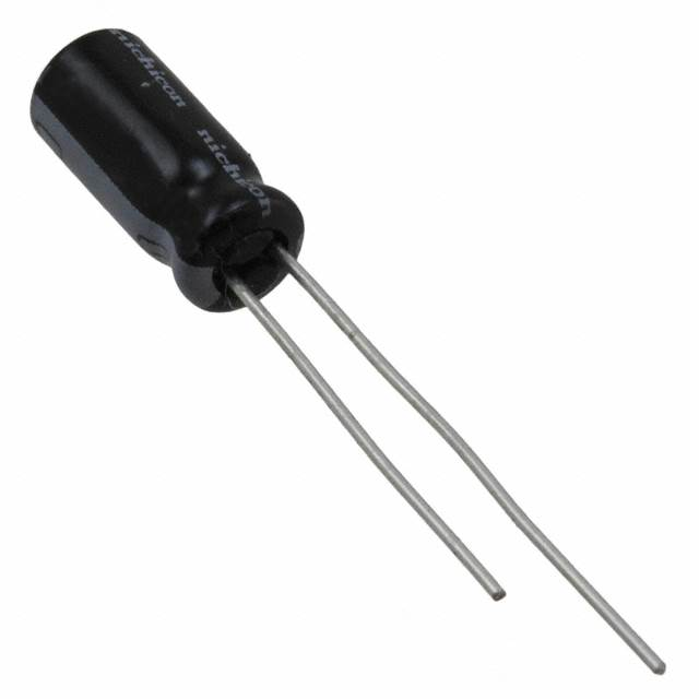
Aluminum Electrolytic Capacitors: These utilize aluminum for the anode and frequently feature polarity indicators, like "+" or "-".
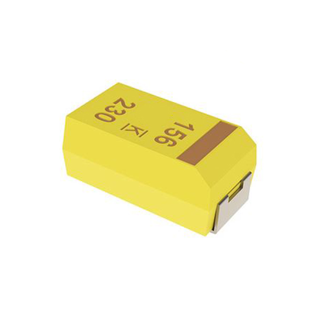
Tantalum Electrolytic Capacitors: These capacitors use tantalum as the anode substance and feature polarity markings, usually denoted by "+" or "-"
The difference between polar and non-polar capacitors
A ideal capacitor is fundamentally non-polarized component in capacitor family. Nonetheless, in practice, certain materials and designs are utilized to attain a significant capacitance, leading to polarity of capacitors displaying. What sets polarized capacitors apart from non-polarized types? Polarized and non-polarized types function based on the same basic principle: they both accumulate and discharge electrical charges. The voltage between the two conductive plates cannot experience sudden changes which may cause catastrophic circuit malfunction. The difference of characteristics of capacitors in polaried type and non-polaried are found in their dielectric materials, performance traits, capacities, and structural designs, which in turn influence their environmental uses and applications.
Various Mediums
Simplely, Medium denotes the material located between the two plates of a capacitor. Polarized capacitors typically use electrolytes as their dielectric substance, enabling them to achieve higher capacitance value relative to non-polarized capacitors of equal volume. Moreover, the capacitance of polarized capacitors with the same volume can differ based on the wide range of electrolyte materials and production methods employed. Moreover, the voltage tolerance of a capacitor is strongly associated with the dielectric material used. Non-polarized capacitors utilize different dielectric substances, including metal oxide layers and polyester. The reversible or irreversible characteristics of the dielectric material dictate the appropriate application settings for polarized and non-polarized capacitors.
Variations in Performance
Performance pertains to the conditions of use, and optimizing demand corresponds with these usage conditions. In televisions, when a metal oxide film capacitor is utilized in the power section for filtering, it must adhere to the capacitance and voltage tolerance specifications necessary for filtering. Alternatively, the whole case might solely accommodate a power supply. Consequently, polarized capacitors are required for filtering. These polarized types are not reversible, indicating that the positive terminal should be linked to the high potential side, whereas the negative terminal should be attached to the low potential side. Typically, electrolytic capacitors greater than 1 microfarad are utilized for coupling, decoupling, and power filtering. Non-polarized capacitors typically have values under 1 microfarad and are used in resonance, coupling, frequency selection, current limiting, and related functions. Additionally, there are high-capacity, high-voltage-resistant varieties, frequently utilized in reactive power supply within electrical systems, phase adjustment in motors, and phase adjustment in variable frequency power supply.
Various Frameworks
In theory, disregarding corona discharge, capacitors of various shapes can be employed according to environmental requirements. Generally, electrolytic capacitors (which are polarized types) are circular, while square types are rarer. Non-polarized capacitors, on the other hand, exist in various forms, including cylindrical, irregular rectangular, sheet, square, round, and their combinations, based on their intended use. Certainly, there are also "formless" varieties, which denote parasitic capacitance. Parasitic capacitance per unit volume must never be ignored in devices operating at high and medium frequencies.
Various settings and applications
Because of their internal materials and design, polarized capacitors (like aluminum electrolytic ones) can reach high capacitance levels. Nonetheless, they show weak high-frequency traits, which makes them appropriate for uses such as power supply filtering. There are polarized types that exhibit superior high-frequency performance, like tantalum electrolytic capacitors, but they usually come at a higher cost.
Non-polarized capacitors are small, affordable, and function effectively at high frequencies; however, they are inappropriate for high capacitance levels. Examples consist of ceramic disc capacitors, monolithic capacitors, and polyethylene (CBB) capacitors. Ceramic disc capacitors are frequently utilized for specific circuit functionality which is high-frequency filtering and oscillation.
Magnetodielectric capacitors are made with ceramic materials functioning as the dielectric, while a silver coating on the surface acts as the electrode. These capacitors provide consistent performance with low loss and leakage, making them suitable for high-frequency applications.
Typically, capacitors featuring insulation materials with a high dielectric constant (like ferroelectric ceramics and electrolytes) between the electrodes are ideal for producing capacitors with substantial capacitance within compact sizes, despite demonstrating elevated losses. In contrast, materials that possess a low dielectric constant (such as ceramics) exhibit minimal losses and are suitable for high-frequency uses.

Common Methods for determining the polarity of capacitor
Axial Lead Electrolytic Capacitor
The polarity of axial lead electrolytic capacitors can be distinguished by the length of the leads and the color of the casing. The longer lead is positive terminal, while the shorter lead is negative. The grey portion on a small area of the casing corresponds to the negative plate, with the other end being positive terminal. If there is packaging, the positive terminal is usually indicated by a "+" sign or the negative terminal by a colored region.
Surface-Mount Aluminum Electrolytic Capacitor
Surface-mount aluminium electrolyte capacitor can be mass-mounted using SMT to improve soldering efficiency, although their capacity is typically smaller than axial types. From the base view, the lead corresponding to the obtuse angle is positive terminal, and the one with the straight edge is negative. On a circuit board, the colored area generally represents the negative terminal, with the opposite end being positive terminal.
Tantalum Capacitor
The polarity of surface-mount tantalum capacitors is distinguished by a stripe on the casing; the end with the stripe is positive terminal, while the other end is negative. On a PCB, the smaller area is positive terminal, or the striped side is positive, or it might be marked with a "+". It's important to note that tantalum capacitors look similar to surface-mount DIODES but have reverse polarity.
Bolt-Type Electrolytic Capacitor
It's crucial to distinguish the polarity when using bolt-type electrolytic capacitors, as reversing them is very dangerous. First, check the marking on the white silver edge; a symbol indicates the negative terminal, while a "+" sign indicates the positive terminal. For new capacitors, the longer lead is positive, and you should also check the white silver edge symbol where the capacitor symbol indicates the negative terminal.
CBB Capacitor
CBB capacitors, commonly found in household appliances, are non-polar type Pay attention to the voltage rating during use CBB capacitors.
Ceramic Capacitor, Porcelain Capacitor, Surface-Mount Capacitor
Ceramic, porcelain, and surface-mount capacitors are non-polarized component and generally have no distinction between positive terminals and negative terminals. They usually have small capacities and are commonly used for filtering signal sources. Any appearance of polarity is temporary. As a type of non-polarized electrolytic capacitor, they don't require polarity identification during installation, allowing for flexible mounting.
What impact does polarity have on capacitor?
The effect of polarity on capacitors' functioning mainly reflects in their performance, longevity, and safety. For polarized capacitors, it is essential to keep the correct polarity to guarantee their proper operation.
Proper Polarity: Capacitor During Standard Functioning
When polarized capacitors experience forward voltage direction (with the positive terminal linked to a higher potential and the negative terminal to a lower potential), they display the following:
Stable Dielectric Layer: The oxide layer in electrolytic capacitors (like Al₂O₃ or Ta₂O₅) stays stable when a forward voltage direction is applied, creating a reliable insulating medium. The capacitance, voltage rating, equivalent series resistance (ESR), and additional parameters match the designated capacitance values.
Minimal Leakage Current: The leakage current is very small (for example, aluminum electrolytic capacitors exhibit a leakage current measured in microamperes), leading to reduced energy loss.
When capacitor polarity mistakes happen: deterioration or harm to capacitor functionality.
Installing a polarized capacitor in reverse (linking the positive terminal to a lower potential and the negative terminal to a higher potential) may result in these problems:
Immediate impacts (at the time of activation)
Oxide layer deterioration: The reverse voltage leads to a reduction of the oxide layer (in electrolytic capacitors) or a breakdown (in tantalum capacitors), causing a circuit malfuction.
Increase in leakage current: Leakage current may rise to mA levels, leading to capacitor overheating and diminished efficiency.
Abrupt reduction in capacitance: The effective capacitance can fall to under 10% of its usual value.
Extended Impact (Extended Reverse Utilization)
In aluminum electrolytic capacitors, the breakdown of the electrolyte may result in the generation of hydrogen gas (which can cause bulging) or leakage. At elevated temperatures, they can burst, especially with high-voltage capacitors, which pose significant risks.
In tantalum capacitors, the failure of the oxide layer can create circuit malfunction, producing elevated temperatures that can result in burning or smoking, ultimately causing irreversible damage.
In solid-state capacitors, the aging of conductive polymers can result in reduced capacitance and heightened ESR (Equivalent Series Resistance).

Why does reversing the polarity of a capacitor lead to damage?
The power of an exploding capacitor should not be overlooked. A reason for capacitor explosions is, in fact, associated with the capacitor polarity orientation.
Within an electrolytic capacitor, there exists an anode and a cathode. The anode is usually constructed from aluminum foil or tantalum metal, with an oxide layer created on its surface acting as the dielectric. The cathode is made up of an electrolyte or a conductive polymer. When the capacitor polarity is flipped, this oxide layer may sustain damage. For aluminum electrolytic capacitors, reverse voltage leads to a reduction of the aluminum oxide layer, diminishing its insulating properties. This results in current flow that generates heat and gas, which can lead to bulging or even explosions.
The scenario with tantalum capacitors is comparable; however, the oxide layer on tantalum is more delicate and can easily fail under reverse voltage, resulting in short circuit malfunction and possible burning at elevated temperatures.
How to select and use polarized capacitors in electronic circuits?
In electronic circuit design, the appropriate choice and application of polarized capacitors are essential for ensuring stability and safety.
Grasping the Features of Polarized Capacitors
Polarized capacitors, including electrolytic capacitors and tantalum capacitors, feature specific positive terminal and negative leads. The connection of their electrode materials, electrolyte, and internal structure requires correct polarity. Reversed polarity of capacitors may cause issues such as internal circuits, leakage of electrolytes, corrosion of electrodes, and in severe situations, capacitor explosions.
Recognizing Polarized Capacitors
Electrolytic capacitors usually feature markings on their bodies that indicate polarity of capacitors, like anode (+) and cathode (-). The anode is linked to a positive voltage, whereas the cathode is linked to a negative voltage. Attentive examination of these indicators enables rapid assessment of polarity. In cases where labels are faded or painted over, alternative techniques like employing a digital multimeter might be required for determining polarity.
Attaching Polarized Capacitors
In practical uses, polarized capacitors need to be connected based on their specified polarity. Non-polarized components do not require this condition and can be connected in any orientation within the circuit requirements.
Selecting the Right Type of Capacitor
Choose the appropriate type of capacitor according to the circuit requirements, including coupling capacitors, filter capacitors, resonance capacitors, and bypass capacitors. Various types of capacitor fulfill different functions in a circuit, making it essential to select according to the particular application context.
Taking into account the Voltage Rating of Capacitors
When choosing capacitors, take into account their voltage rating to guarantee they can handle the necessary voltage in the circuit and avoid damage from high voltage.
Utilizing a Multimeter for Testing
If the labels on a capacitor are ambiguous, a digital multimeter can be utilized for testing. Adjust the multimeter to the “diode” mode, attach the red probe to the capacitor’s terminal, and take measurements in both forward and reverse directions. If the forward measurement indicates low resistance and the reverse displays no reading or “OL,” the anode and cathode have been accurately identified. A low resistance measurement in the reverse setup signifies a mistake.


