How to Read Resistor Color Code: A Complete Guide for Engineers &Hobbyists
What Is a Resistor Color Code?
The color code on a resistor indicates its value.
The color code system employed by resistors is one of the most reliable and straightforward methods for indicating resistance values. This is because, in many instances, the printed values on resistors wear off or become illegible during transportation and handling, making identification difficult.
Colored bands around the resistor indicate the resistor's color code. Since all leaded resistors are essentially cylindrical, printing numbers or codes directly onto the resistor is impractical. Furthermore, the use and handling of resistors often erase or obscure printed markings. Suppose the resistor's coding scheme is partially marked, in which case, the various rings around the resistor (color-coded) can be used to determine the resistor's parameters and value. The color-coding system for a resistor depends on the required precision and tolerance level. Different resistors use color-coding systems based on the same outline, yet each conveys distinct information. The primary color coding systems observable on resistors include:
- Four-Band Resistor Color Code Chart
- Five-Band Resistor Color Code Chart
- Six-Band Resistor Color Code Chart
Resistor color codes are provided based on the number of rings used on the resistor.
Four-Band Resistor Color Code Scheme
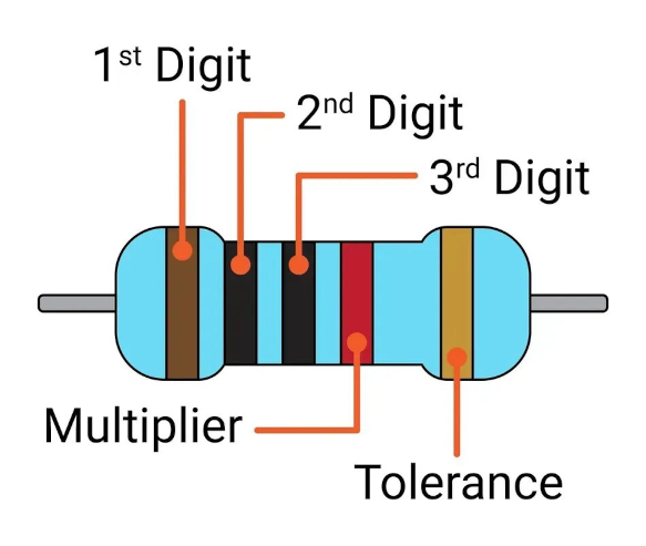
Series values using the four-band color code scheme include E24, E6, and E12. The maximum practical value accommodated can be up to two digits. The maximum acceptable resistor value range is E24, with a tolerance of ±2%. The four-band color code provides information about various resistor parameters, such as temperature coefficient, value, and tolerance class. The band closest to the resistor terminals is referred to as "Band 1." Among these four bands, the significant digits of the resistance value are represented by the first two bands, while the third band's color code indicates the multiplier.
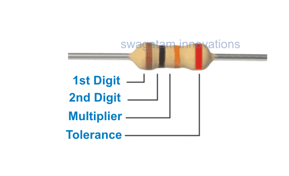
For example, the color code scheme for the resistor shown in the figure above is brown, black, and orange, with the fourth band on the right being red. The first two bands (brown and black) represent the significant digits of the resistance value (10), while the third band (orange) represents the multiplier (1000). The fourth red band indicates the resistor's tolerance level of ±2%. Therefore, the resistance value can be interpreted as 10 kΩ.
Note: If a resistor has only three bands, the first two bands represent the significant digits of the resistance value, and the third band represents the multiplier. There is no fourth band indicating tolerance.
Five-Band Resistor Color Code Scheme
Due to the higher tolerance requirements of the E192, E48, and E96 series resistors (typically ±1%), a five-band color code scheme is employed. Consequently, three bands are required to represent the significant figures of the resistance value, allowing for one additional band to be observed. In all other respects, the five-band resistor color code scheme is similar to the four-band resistor color code scheme.
For example, the bands on the above resistor are orange, brown, blue, red, and brown. The first three bands represent the significant digits of the resistance value, namely 316; the fourth band represents the resistance multiplier, which is 100.
The fifth band indicates the tolerance value of ±1%. Therefore, the resistance value can be written as 31.6 kΩ or 31,600 Ω.
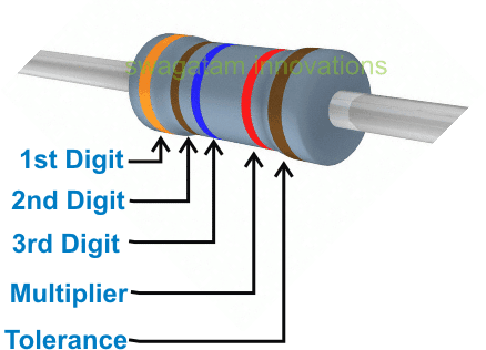
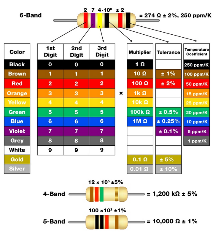
Resistor Color Code Chart with Six Bands
The six-band resistor color code scheme provides the maximum information about resistor parameters. Resistors in a series using the six-band color code are E192, E48, and E96. The six-band scheme is suitable for resistors with very high tolerance values within the ±1% range.
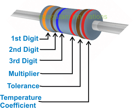
As shown in the figure above, the resistor's color code consists of six bands: orange, brown, blue, red, brown, and red. The first three bands on the resistor represent the significant digits of the resistance value (e.g., 316), while the fourth band represents the multiplier (e.g., 100). The fifth band indicates a 1% tolerance level. The sixth and final band denotes the temperature coefficient, which is 50ppm/ºK.
Therefore, the resistor's value can be written as 31.6 kΩ or 31,600 Ω.
How to Read Resistor Color Codes Step by Step
Read the Significant Digits
We start by reading the first 2 or 3 significant digits. Each resistor band color corresponds to a specific number.
Color-to-digit conversion table:
Black - 0
Brown - 1
Red - 2
Orange - 3
Yellow - 4
Green - 5
Blue - 6
Violet - 7
Gray - 8
White - 9
For 4-band resistors, the first two bands represent the significant digits.
Example: Brown (1) Black (0) → Significant digits are 10.
For 5-band resistors: The first three bands represent significant digits.
Example: Brown (1) Black (0) Black (0) → Significant digits are 100.
For 6-band resistors, the first three bands represent significant digits, and the fourth band indicates the multiplier.
Apply the Multiplier
The multiplier band (third band on 4-band resistors, fourth band on 5-band or 6-band resistors) determines how many times 10 you must multiply the significant digits. It uses the same colors as the significant digits, but its meaning is "how many zeros follow."
Key multiplier examples:
Black - x1 Ω (10^0)
Brown - x10 Ω (10^1)
Red - x100 Ω (10^2)
Orange - x1 kΩ (10^3)
Yellow - x10 kΩ (10^4)
Green - x100 kΩ (10^5)
Blue - x1 MΩ (10^6)
Gold - x0.1 Ω (10^-1)
Silver - x0.01 Ω (10^-2)
Check the Tolerance (and Temperature Coefficient)
Tolerance: The tolerance band indicates the range by which the actual resistance value may deviate from the nominal value. It is typically the last band (in 4-band and 5-band resistors) or the second-to-last band (in 6-band resistors).
Brown - ±1%
Red - ±2%
Green - ±0.5%
Blue - ±0.25%
Violet - ±0.1%
Gray - ±0.05%
Gold - ±5%
Silver - ±10%
Colorless - ±20%
Temperature Coefficient: The sixth ring, which appears only on 6-band resistors, indicates the degree to which the resistance changes with temperature, typically measured in ppm/K (ppm/°C).
Brown - 100 ppm/°C
Red - 50 ppm/°C
Orange - 15 ppm/°C
Yellow - 25 ppm/°C
Resistor Color Code Chart & Examples
A standard reference tool is the resistor chart, which provides a quick guide to standard resistor values and color codes. These charts are invaluable for identifying resistor markings (such as color bands) or for selecting the closest standard value during circuit design. This article provides a comprehensive guide to resistor charts, covering both theoretical concepts and practical applications: resistor values, units, and tolerances; the structured E-series system; resistor color band systems and decoding examples; practical resistor value selection for specific applications; and a complete analysis of resistor color bands.
Color Code Fundamentals Chart:
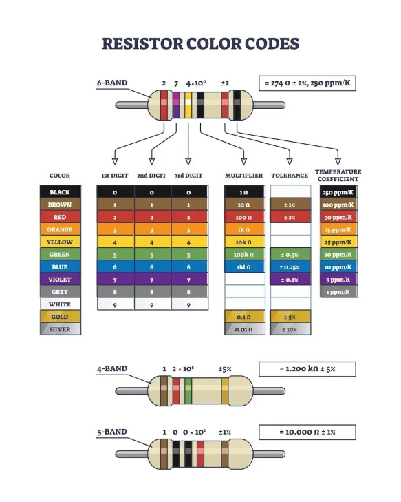
Each color corresponds to a digit from 0 to 9, a multiplier, or a tolerance, as shown in the table below:
|
Band Color |
Numerical Value (Significant Figure) |
Multiplier (Decimal) |
Tolerance (%) |
|
Black |
0 |
×1 (10⁰) |
|
|
Brown |
1 |
×10 (10¹) |
±1 |
|
Red |
2 |
×100 (10²) |
±2 |
|
Orange |
3 |
×1,000 (10³) |
|
|
Yellow |
4 |
×10,000 (10⁴) |
|
|
Green |
5 |
×100,000 (10⁵) |
±0.5 |
|
Blue |
6 |
×1,000,000 (10⁶) |
±0.25 |
|
Violet |
7 |
×10,000,000 (10⁷) |
±0.1 |
|
Gray |
8 |
×100,000,000 (10⁸) |
±0.05 (Rare) |
|
White |
9 |
×1,000,000,000 (10⁹) |
|
|
Gold |
|
×0.1 (10⁻¹) |
±5 |
|
Silver |
|
×0.01 (10⁻²) |
±10 |
|
Colorless |
|
|
±20 (Default) |
Four-Band Resistors
The four-band code is the most common marking method for standard resistors (typically with ±5% or ±10% accuracy). It consists of the following components: First Digit, Second Digit, Multiplier, and Tolerance. The first two bands indicate the first two digits of the value, the third band is the multiplier, and the fourth band represents the tolerance. For example, a resistor with color bands: Yellow - Red - Green - Gold:
First digit - Second digit - Multiplier - Tolerance. The first two bands represent the first two digits of the value, the third band is the multiplier, and the fourth band indicates the tolerance. For example, a resistor with the color band sequence: Yellow - Red - Green - Gold:
Yellow = 4 (first digit)
Red = 2 (second digit)
Green = 100000 (multiplier, 10^5)
Gold = ±5% (Tolerance)
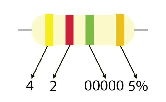
This code translates to "42 × 100,000 Ω, ±5%," meaning 4,200,000 Ω ±5%, or 4.2 MΩ ±5%. If no tolerance band is present (in older 3-band codes), the default tolerance is considered ±20%.
Five-Band Resistors
Precision resistors (±1% or ±2%) often utilize 5-band color codes to include a third significant digit, providing increased accuracy. The pattern is:
First digit – Second digit – Third digit – Multiplier – Tolerance.
For example, a resistor marked with brown – black – black – red – Gold is decoded as:
Brown = 1 (first digit)
Black = 0 (second digit)
Black = 0 (third digit)
Red = 100 (multiplier, i.e., 10^2)
Gold = 5% tolerance
The code will display as "100 x 100 Ω ±5%", i.e., 10,000 Ω±5% or 10 kΩ ±5%
Six-Band Resistors
Some resistors, particularly high-precision or specialized types, feature a sixth color band. This sixth band typically indicates the resistor's temperature coefficient (TC), measured in ppm/K (parts per million per Kelvin). The first five bands are read identically to those of five-band resistors (three digits, multiplier, tolerance), while the sixth band's color indicates the temperature coefficient.
Standard temperature coefficient colors include:
|
Color |
Temperature Coefficient (ppm/K) |
|
Brown |
100 |
|
Red |
50 |
|
Orange |
15 |
|
Yellow |
25 |
|
Blue |
10 |
|
Violet |
5 |
Practical Applications: Select & Use Resistors Correctly
Understanding resistor color codes is just the first step. What matters more is correctly selecting and using them in actual circuit designs. This section explores several typical application scenarios and explains how to translate color codes into appropriate selection decisions.
Color Code Identification and Selection for LED Current Limiting
LEDs (light-emitting diodes) require a constant current to function correctly without burning out, where resistors play a crucial "current limiting" role.
Suppose you have a 5V power supply and an LED with a forward voltage of 2.2V and a rated current of 20mA. According to Ohm's Law, the required current-limiting resistor value is R = (Supply Voltage - LED Forward Voltage) / Current = (5V - 2.2V) / 0.02A = 140Ω.
From Calculation to Component Selection:
Identification and Verification: You locate a resistor in your component bin marked with the color code: Brown, Yellow, Brown, Gold. Reading: Brown (1) Yellow (4) Brown (x10) → 14 x 10 = 140Ω, Gold (±5%). This perfectly matches the calculated value.
Power Selection: Power dissipated by the resistor P = I² * R = (0.02A)² * 140Ω = 0.056W. A standard 1/4W (0.25W) resistor is sufficient, as it far exceeds the calculated power consumption with ample margin.
Key Point: In this application, the accuracy of the resistance value (typically ±5% is sufficient) and the resistor's power rating are equally important. Selecting a resistor with an insufficient power rating will cause it to overheat and burn out.
Resistor Selection in Microcontroller Interfaces and Voltage Divider Circuits
In digital and sensor circuits, resistors are often used to construct voltage dividers, reducing a high voltage to a range safely readable by the ADC pins of microcontrollers (e.g., Arduino, STM32).
Suppose you need to measure a 0-12V battery voltage, but the microcontroller's ADC can only accept up to 5V. You can use two resistors (R1, top connected to the battery's positive terminal, and R1 bottom connected to R2 top, which in turn is connected to the ADC pin, and R2 bottom connected to ground) to form a voltage divider. If you choose R1 = 10kΩ and R2 = 6.8kΩ, then when the battery is at 12V, the voltage at the ADC pin will be 12V * (R2 / (R1 + R2)) = 12V * (6.8k / 16.8k) ≈ 4.86V, which is within the safe range.
From Calculation to Component Selection:
Accuracy Requirements: The precision of the voltage division ratio directly impacts measurement results. In this case, resistors with tighter tolerances, such as those with a ±1% tolerance (brown band), should be selected over those with a ±5% tolerance (gold band).
Resistance Stability: For pull-up/pull-down resistors (e.g., on I²C buses), standard recommended values (e.g., 4.7 kΩ or 10 kΩ) are common, and resistors with ±5% tolerance suffice. However, understanding "How to calculate resistor color code" is bidirectional here: you must both find physical resistors that match the calculated theoretical values and verify that the resistance values of your existing resistors are suitable for your precision circuit based on their color bands.
Key point: In these applications, resistance accuracy and stability are more critical than power rating, as the Current flowing is typically very low.
From Color Code to Specifications: Power Rating, Package, Temperature Coefficient, Reliability
Color codes indicate the resistance value, tolerance, and even the temperature coefficient (for 6-band resistors). But a resistor's complete specifications extend far beyond this.
Power Rating and Package: The color code does not directly indicate power rating. Power is typically determined by the resistor's physical dimensions (package).
- 1/4W (0.25W): The most common through-hole resistor (carbon film, metal film), approximately 6.5mm in size.
- 1/2W (0.5W): Larger size, used in higher power circuits.
- 1W, 3W, 5W...: Significantly larger size, often featuring heat sinks or cemented construction, used in high-current applications like power supply circuits.
- Selection logic: Always ensure the resistor's rated power is greater than the calculated power dissipation multiplied by 1.5 (safety margin).
Temperature Coefficient:
- Importance: In equipment with significant ambient temperature fluctuations (e.g., automotive electronics, outdoor devices) or high-precision reference circuits, resistance values should not vary excessively with temperature.
- Color Code Representation: The sixth band on a 6-band resistor specifically indicates the temperature coefficient (e.g., brown = 100 ppm/°C). This means the resistance value changes by 100 parts per million (0.01%) for every 1°C change in temperature. For high-precision circuits, resistors with lower temperature coefficients should be selected (e.g., red, 50 ppm/°C, or blue, 10 ppm/°C).
- Reliability Rating: This falls outside the color code system. However, in critical sectors such as the military, aerospace, and medical applications, parameters such as failure rate and long-term stability must be verified through data sheets.
Throughout the selection and application process, "How to calculate resistor color code" actually encompasses two distinct levels of meaning:
- From circuit-theory calculations to physical selection: this is the forward process. You calculate the circuit's required theoretical resistance (e.g., 4.7 kΩ) using Ohm's Law and voltage division, among other methods. Then, you consult a color code chart or use a calculator to find the corresponding color band sequence (e.g., yellow, violet, red, gold). Finally, you locate a resistor matching this sequence in the component library while confirming its power rating and package meet circuit requirements.
- From Physical Identification to Circuit Verification: This is the reverse process. You take an unknown resistor and calculate its resistance (e.g., 10 kΩ) by interpreting its color bands (e.g., brown-black-orange-gold). Then, you evaluate whether this resistance value, tolerance, and possible temperature coefficient are suitable for the circuit you are designing or repairing. If it is unsuitable, replace it with a resistor of the correct resistance value.
Why Choose unikeyic Electronics for Resistors & Color Code Resources
As we've learned, correctly identifying and selecting resistors is critical to the success of electronic design and manufacturing. However, having a reliable and resourceful component supplier is equally vital. Unikeyic Electronics is precisely such a trusted partner—we not only offer an extensive range of components but are also committed to being your technical resource hub.
- Comprehensive Products & Professional Technical Support
When selecting a resistor supplier, you need more than just products—you need a partner that delivers complete solutions.
Extensive Resistor Selection: Unikeyic offers a comprehensive range of resistor products, including the most common carbon film and metal film resistors, high-precision chip resistors, high-power wirewound resistors, and current-sensing resistors. Whether your project involves simple LED lighting or complex industrial control systems, you'll find the right model here.
Comprehensive Technical Documentation Support: We recognize that accurate data is the foundation of effective design. Therefore, we provide readily available datasheet downloads for the vast majority of our products. These official technical documents contain all the information you need—rated power, temperature coefficient, dimensional drawings, derating curves, and more—empowering you to make the most precise selection decisions.
Free Practical Color Code Resources: To help you work faster and more accurately, Unikeyic has created clear, professional Resistor Color Code Charts available for free download as PDFs. Print them for your workspace or save them digitally for instant reference—say goodbye to reading confusion.
- Your Dedicated Tool and Resource Center
To bridge theory and practice, we offer convenient access to products.
Direct Access to Product Catalog: Our resistor product catalog offers precise categorization and robust filtering. Could you quickly find the products you need based on parameters such as resistance value, tolerance, power rating, and package type?
- Explore Products: [Browse Our 4-Band/5-Band Resistor Products]
Theory meets practice, resources at your fingertips. Begin your journey of efficient procurement and technical exploration at Unikeyic today.
Browse our 4-band and 5-band resistor products: With ample inventory and competitive pricing, we meet diverse needs from prototyping to mass production.
Download Color Code PDF Quick Reference: Access our free, carefully curated resource to boost your workflow efficiency.
Visit Unikeyic's official website now for one-stop solutions to your component and technical resource needs!
Summary
Through this detailed analysis, we have systematically reviewed the core knowledge system of resistor color codes. From the definition and origin of color codes, to step-by-step reading methods (orientation, reading significant digits, applying multipliers, checking tolerance and temperature coefficient), to common errors and practical tips, and finally to proper selection and application in actual circuits—we have comprehensively mastered this essential foundational skill for electronics engineers.
Resistor color code identification extends far beyond a theoretical basic skill. It serves as the cornerstone for engineers to select components, precisely design circuits correctly, and efficiently troubleshoot faults. Being able to quickly and accurately interpret color codes means you can:
- Select the appropriate resistance value and power rating for LED current-limiting circuits.
- Select high-precision, low-temperature-drift resistors for microcontroller voltage divider networks;
- Quickly identify and replace damaged components during repairs.
This skill bridges the gap between abstract color bands and concrete circuit parameters, serving as the vital link between theoretical design and physical implementation.
If, after reading this article, you want to practice or select suitable resistors for your project, we encourage you to explore further and search for relevant components on the Unikeyic official website. Leverage our extensive product catalog, detailed datasheets(such as 2-1879445-5), and PDF quick reference guides to make your work and studies more efficient. Take action now and turn knowledge into successful projects!
FAQs:
QI: How do I know which end of the resistor to start reading from?
- Remember the "Gold/Silver on the Right" rule: This is the most reliable method. Position the end of the resistor with the gold or silver band toward your right, then read from left to right. Gold and silver bands are rarely used as the first band in the significant digits, making them excellent "termination" markers.
- Observe the color band spacing: Look closely—the starting end's bands (significant digits) are usually closer together than the ending end's bands (multipliers and tolerance). You'll see a "wider gap" separating the significant digits bands from the multiplier/tolerance bands. The starting end is the one with denser bands.
- Contrast-based identification: If the resistor lacks gold/silver rings (e.g., 1% tolerance brown-band resistors), the first band's color is usually dark or vivid—brown, red, orange, yellow, green, blue, Violet, gray, or white—while the final band (tolerance band) may be brown. In such cases, the spacing rule becomes the primary means of identification.
Q2: How to Avoid Overlooking Tolerance or Temperature Coefficient Bands When Reading?
- Identify Ring Count: First, count the number of color bands on the resistor. For a 4-band resistor, the last band indicates tolerance (usually gold or silver). For a 5-band resistor, the previous band suggests tolerance. For a 6-band resistor, the last band indicates the temperature coefficient.
- Understanding Tolerance Importance: A "1000Ω ±5%" resistor may actually measure between 950Ω and 1050Ω. Precision circuits require resistors with ±1% (brown) or higher accuracy.
- Identifying the temperature coefficient: In high-end or temperature-sensitive equipment, the sixth band (temperature coefficient) is critical, indicating how resistance changes with temperature.
Q3: How to Read Resistance Values with Faded or Missing Color Bands?
- Reroute with a multimeter: This is the most direct and reliable method. Use a digital multimeter's resistance setting to measure the actual value directly. This is the ultimate technique for verifying color-band readings and resolving any uncertainties.
- Observe under a magnifier: Sometimes colors are hard to distinguish; they may become clear under a magnifying glass or smartphone macro lens.
- Infer based on circuit board location: During repairs, you can estimate the resistor's resistance range by referring to the circuit schematic or the values of adjacent components on the board.
- If the color bands are completely unreadable and circuit inference is impossible, the safest approach is to treat it as a damaged component and replace it immediately.
Q4: What is a Resistor Color Code Calculator?
A resistor color code calculator is an online tool or mobile app that lets you select each color band on a resistor interactively. Automatically calculates the resistor's resistance, tolerance, and temperature coefficient. Conversely, you can input the resistance value to display the corresponding color band sequence.
Take the online calculators provided by electronics websites, such as Circuit Home, as an example:
- Select the number of color bands on the resistor (4-band, 5-band, or 6-band).
- Select the color you see for each band using the dropdown menu or by clicking the color swatches.
- The calculation results (resistance value, tolerance) appear instantly.
Advantages of using the tool:
- Eliminate human error: Avoid mistakes caused by misjudging colors or by mixing them up.
- Fast and efficient: Especially useful for batch identification.
- Two-way lookup: Determine resistance values from colors or reverse-lookup color codes from resistance values, simplifying resistor selection during circuit design.
While manual reading remains an important skill, using tools significantly boosts efficiency and accuracy when dealing with large quantities of resistors or when colors are difficult to distinguish.
Q5: How to Remember Electrical Resistor Color Codes?
- Classic English Mnemonic:
Better Be Right Or Your Great Big Venture Goes Wrong.
(Black-0, Brown-1, Red-2, Orange-3, Yellow-4, Green-5, Blue-6, Violet-7, Gray-8, White-9)
- Classic Chinese Mnemonic (better aligned with Chinese color order):
One brown, two red, three orange, four yellow, five green, six blue, seven violet, eight gray, nine white, Black is zero—remember them all.
Brown is one, red is two, orange is three, yellow is four, green is five, blue is six, violet is seven, gray is eight, snow white is nine, black is zero. Gold five, silver ten is the error.
(This mnemonic cleverly aligns numbers with color sequence while integrating gold/silver as tolerance indicators—efficient.)
Tip: Even if you're confident in reading color codes, it's always a good habit to double-check with a multimeter before soldering resistors onto a circuit board. This not only corrects reading errors but also screens out resistors whose values have changed due to damage.
Q6: How to Calculate the Resistor Color Code?
- Calculating from circuit theory: This is the forward process. You calculate the circuit's required theoretical resistance (e.g., 4.7 kΩ) using Ohm's Law and voltage division, among other methods. Then, you consult a color code chart or use a calculator to find the corresponding color ring sequence for this theoretical value (e.g., yellow-Violet-red-gold). Finally, you search your component library for a resistor that matches this sequence, confirming that its power rating and package type meet circuit requirements.
- From physical identification to circuit verification: This is a reverse process. You obtain an unknown resistor and calculate its resistance (e.g., 10 kΩ) by interpreting its color bands (e.g., brown-black-orange-gold). You then evaluate whether this resistance value, tolerance, and possible temperature coefficient are suitable for the circuit you are designing or repairing. If unsuitable, you must replace it with a resistor of the correct resistance value.
Recommended Resistor:
Positive Temperature Coefficient (PTC) Resistors and Applications