Understanding 10k Resistor Color Codes Quickly
The color bands on Ohm resistors are used to indicate resistance value, tolerance band, and even temperature coefficient. Understanding the significance and calculation principles of these color bands makes identifying resistor color codes straightforward. This simple chart can help you master the rules of 10k resistor color code with ease.
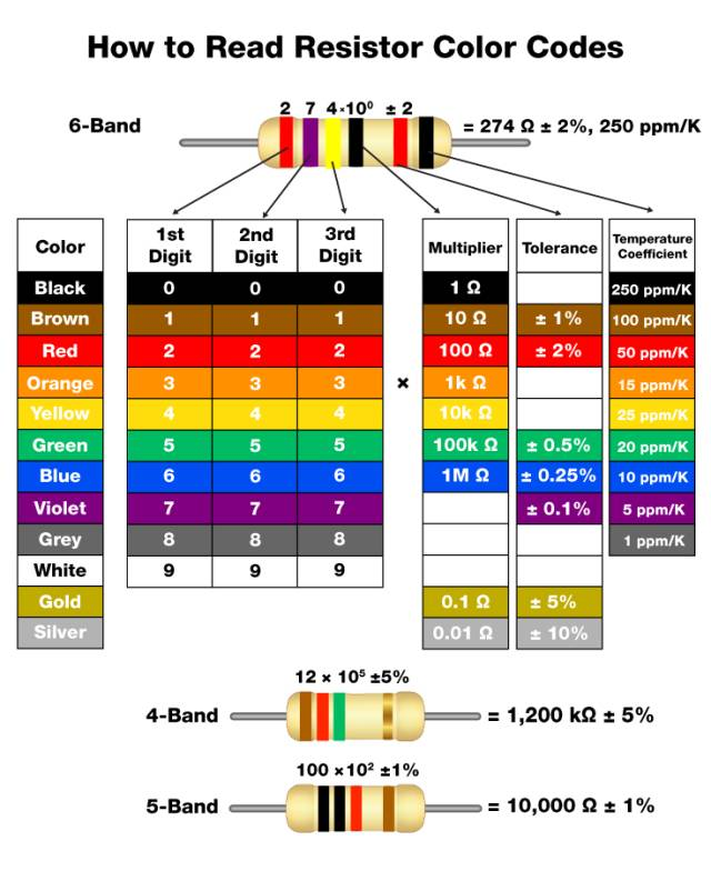
The type of resistor vary in resistance values, shapes, and physical sizes. In fact, all leaded Ohm resistors rated at one watt or more come with specific color band combinations to denote their resistance value, tolerance value, and potentially temperature coefficient. Resistors may have between three to six color bands, with the 4-band 10K resistor version being the most common. The first few bands represent significant digits of the resistance value. Following these is a multiplier band, which shifts the decimal point either left or right. The final band indicates tolerance and sometimes temperature coefficient.
Let's start by examining the band color code chart below and work through some examples:
3-Band Resistors or 4-Band Resistors
The first two color bands signify the first two digits of the resistance value in ohms. On three or 4th-band resistors, the third band represents the multiplier. This multiplier adjusts the decimal place position to express any magnitude from megaohms to milliohms. The fourth band denotes tolerance. Note that if a 3rd-band resistor lacks this band, the default tolerance is ±20%.
5-Band Resistors or 6-Band Resistors
High-precision resistors include an additional band for indicating a third significant digit. If your resistor type has 5th bands or 6th bands, the third band is for this digit, combining with the first and second bands to form the number. Moving further right, the fourth band is the multiplier, and the fifth band shows tolerance. 6-band resistor color code are essentially similar to five-band ones but provide an extra band to indicate reliability or temperature coefficient (ppm/K). For example, the commonly used brown sixth band signifies that a 10°C change results in a 0.1% actual resistance change.
Common Questions about Resistor Color Codes
1.How do I know which end to start reading a resistor band from?
Often, some initial bands are spaced more closely together or are concentrated at one end of the resistor. Hold the resistor component so that the clustered previous bands are on the left side. Then read the information from left to right.
A metallic-colored band will never be at the far left of a resistor. If a larger resistor has a gold band or silver band at one end, its tolerance is 5% or 10%. Position such series resistor so that this band is on the right, then read from left to right.
Generally, standard resistor values of wide range from 0.1 ohms to 10 megaohms. Therefore, the third band of a four-band resistor is usually blue (10^6) or a color representing a lower value, while the fourth band of a five-band resistor is typically green (10^5) or a color representing a lower value.
2.Why doesn't my high-voltage resistor have a metallic-colored band?
In voltage divider circuit, on high-voltage types of resistors, yellow and gray replace gold color and silver color to avoid metal particles in the coating.
3.What is a zero-ohm resistor?
Zero-ohm resistors are easily identifiable by their single black band and primarily serve as jumpers in electronic circuits, connecting traces on printed digital circuit boards. They use the same packaging as resistors in circuits, enabling automated equipment used for placing resistors to install them without needing separate machinery for jumpers.
4.Are there tricks for memorizing the order of colors in the chart?
While there are various mnemonic electronic devices available online for memorizing resistor color codes, their effectiveness varies. One alternative method views black as "nothing" or "0," while white is seen as the combination of all colors, the highest value "9." In the middle of the chart are standard rainbow colors ordered to represent numbers 2 through 7, recalling the childhood mnemonic ROY-G-BIV (red, orange, yellow, green, blue, indigo, violet), minus indigo. Remember that brown between black and red is "1," and gray between violet and white is "8," and you'll have it down!
5.What is a reliability band?
Military-grade four-band resistors often include an additional band indicating reliability, or failure rate (%) per 1,000 reliable operation hours. This feature is rare in commercial electronics.
The History of Resistors
Resistors have a rich history as fundamental electronic components in sensitive circuits. After early scientists studied the conductivity of various materials and discovered electric current, they gradually developed the concept in electronics resistance. They identified copper, gold, and aluminum as excellent conductors with low resistance, while air, mica, and ceramic were considered resistors due to their ability to significantly impede the flow of electricity. Despite this understanding, the reliable resistors we recognize today did not emerge until 1961, when Otis Boykin invented the first affordable and dependable resistor, enabling precise control over the amount of current limiting delivered to a specific electrical component.
Boykin's breakthrough reduced the susceptibility of resistors to ambient temperatures and oscillations, ultimately making low-cost production feasible. As a result, Boykin’s innovative resistors were quickly adopted by the U.S. military, IBM, and many consumer electronics manufacturers, becoming ubiquitous in everything from household appliances and computers to guided missiles.
Today, resistors are omnipresent in electronic devices. As passive components, they consume energy but never supply it. Resistors serve various purposes in analog circuits, such as accurate regulation for the current limiter entering an LED or controlling the total voltage directed to active components like transistors. They can be used to terminate transmission lines and prevent reflections or function as pull-up resistors or pull-down resistors in microcontroller GPIOs to enhance electronic system stability. Combinations of resistors and capacitors create timing sources necessary for common applications like flash photography or electronic RC (resistor-capacitor) circuits. When connected in series, resistor "daisy chains" act as voltage dividers, which are particularly useful for circuit components that operate at voltage level lower than the input voltage.