10k Ohm Resistor Color Code Explained: 4-Band, 5-Band, SMD Markings & Uses
In electronic circuit design, DIY projects, and equipment maintenance, the 10k ohm resistor stands as one of the most fundamental components. Its color band coding serves as the primary reference for identifying rapid resistance values. This article systematically breaks down the color band rules, SMD markings, reading techniques, circuit applications, and purchasing recommendations for 10k resistors. It empowers engineers and electronics enthusiasts to master the precise usage of this critical component.
Why 10k is the most used Resistor
The 10kΩ resistor serves as a versatile "workhorse" component in electronic systems due to its adaptability and stable parameters. Core applications include:
- Voltage Divider Circuits: In control systems, such as Arduino and microcontrollers, voltage divider circuits are often formed with other resistors to scale analog signals from sensors (e.g., NTC thermistors, photoresistors) down to the 0-5V range recognizable by controllers.
- Bias resistors: Provide appropriate static operating points for transistors and operational amplifiers, preventing device damage from excessive current; Pull-up/pull-down resistors: In digital circuits, connect GPIO (General Purpose Input/Output) pins to power or ground to prevent signal instability caused by floating pins, commonly found in button and sensor interface designs.
- Current limiting protection: Series-connected in circuits with LEDs, miniature relays, and similar components to restrict operating current and prevent overload damage.
Whether in consumer electronics (e.g., phone chargers), industrial control (e.g., PLC modules), or DIY projects (e.g., smart cars), the 10k resistor's high versatility makes it an essential stock component.
What is a 10k Ohm Resistor? Definition and Parameter Comparison
- A 10 kΩ resistor is a passive electronic component with a resistance value of 10,000 ohms (10 kilohms). Its core function is to limit or regulate current and voltage in a circuit through its own impedance.
- Definition & equivalent forms: In practical applications, it is often used in combination with other common resistance values, and the applicable scenarios for different resistance values vary significantly:
|
Resistance Specifications |
Core Application Scenarios |
Typical Partner Components |
|
4.7kΩ |
Low-current signal voltage division (e.g., weak sensor signals), LED indicator current limiting |
Photoresistor, micro LED |
|
10kΩ |
General-purpose voltage division, pull-up/pull-down, and transistor bias |
NTC thermistor, microcontroller GPIO pin |
|
100kΩ |
High-impedance circuits (e.g., op-amp input stage), RC delay circuits |
Capacitors (forming RC circuits), high-precision sensors |
From a parameter perspective, the "versatility" of the 10k resistor is evident in its ability to meet most circuits' current limiting requirements without causing signal attenuation due to excessive resistance. It represents one of the optimal choices, striking a balance between performance and practicality.
What is the color code for a 10k resistor?
Color bands are the core identifier for through-hole 10k resistors, with combinations of colored bands indicating resistance value and tolerance (accuracy).
Common four-band and five-band specifications correspond to the following parameters:
|
Color Band Type |
Color Band Combination |
Resistance Value Calculation |
Tolerance (Accuracy) |
Application Scenarios |
|
Four-Color Band |
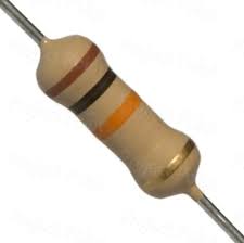
Brown + Black + Orange + Gold |
1st Band (Brown = 1) + 2nd Band (Black = 0) → Base "10"; 3rd Band (Orange = ×10³) → 10×10³=10,000Ω (10kΩ)
|
±5% |
Consumer electronics, DIY projects, and other applications with lower precision requirements |
|
Five-Color Band |
Brown + Black + Black + Red + Brown |
1st band (Brown = 1) + 2nd band (Black = 0) + 3rd band (Black = 0) → Base "100"; 4th band (Red = ×10²) → 100×10²=10,000Ω (10kΩ)
|
±1% |
Industrial control, medical equipment, precision instruments, and other applications requiring high accuracy |
Quick Color Band Reference Chart (Including 10Ω vs. 10kΩ Comparison)
Novices often confuse color bands for low-resistance and high-resistance resistors. Below is the Quick Color Chart. Let you know what colors are used for a 10 ohm resistor:
|
Nominal Resistance (Ω) |
Color Band Sequence |
Color Ring Color Explanation |
Tolerance |
Common Types |
Primary Applications |
Key Differences |
|
10 |
Brown – Black – Black – Gold |
1 (Brown) 0 (Black) × 10⁰ (Black) |
±5% |
Metal Film, Alloy Resistor |
Current sampling (e.g., motor circuit, power supply circuit current detection), low-voltage circuit current limiting, PCB impedance matching |
Extremely low resistance, primarily used in high-precision current sampling scenarios to minimize voltage loss during sampling; more suitable than 100Ω for current limiting in small-current loops to prevent excessive voltage drops that could affect normal equipment operation |
|
100 |
Brown – Black – Brown – Gold |
1 (Brown) 0 (Black) × 10 (Brown) |
±5% |
Carbon Film / Metal Film |
Current sensing, motor current limiting |
Lower resistance values, suitable for current limiting and low-resistance voltage division |
|
220 |
Red – Red – Brown – Gold |
2 (Red) 2 (Red) × 10 (Brown) |
±5% |
Metal film |
LED current limiting, power interface |
Commonly used for LED series current limiting, high stability |
|
330 |
Orange – Orange – Brown – Gold |
3 (Orange) 3 (Orange) × 10 (Brown) |
±5% |
Carbon film |
Indicator lamp, signal circuit |
Slightly higher resistance than 220 Ω, stronger current limiting |
|
470 |
Yellow – Purple – Brown – Gold |
4 (Yellow) 7 (Purple) × 10 (Brown) |
±5% |
Carbon film |
Switching Interface, Audio Circuit |
Universal resistance values, balancing current control and signal amplitude |
|
1 kΩ |
Brown – Black – Red – Gold |
1 (Brown) 0 (Black) × 100 (Red) |
±5% |
Metal film |
Voltage divider, op-amp input |
Most commonly used general-purpose resistor, with a typical value for signal-level applications. |
|
2.2 kΩ |
Red – Red – Red – Gold |
2 (red) 2 (red) × 100 (red) |
±5% |
Carbon film |
Analog Input Current Limiting |
Slightly higher resistance, suitable for protecting circuit inputs |
|
4.7 kΩ |
Yellow – Violet – Red – Gold |
4 (Yellow) 7 (Purple) × 100 (Red) |
±5% |
Metal film |
Analog preamplifier, filter circuits |
Commonly used in bias, sampling, and filter networks |
|
10 kΩ |
Brown – Black – Orange – Gold |
1 (Brown) 0 (Black) × 1000 (Orange) |
±5% |
Metal film |
MCU Pull-Up/Pull-Down, Feedback Circuit |
Most Common Logic Level Pull-Up Resistor |
|
47 kΩ |
Yellow – Purple – Orange – Gold |
4 (Yellow) 7 (Purple) × 1000 (Orange) |
±5% |
Carbon Film |
Analog Signals, RC Filtering |
Higher resistance values reduce current consumption |
|
100 kΩ |
Brown – Black – Yellow – Gold |
1 (Brown) 0 (Black) × 10000 (Yellow) |
±5% |
Metal film |
Amplifier feedback, level detection |
High resistance, commonly used for high-impedance inputs |
How to Read a Resistor Color Code? A Technique Even Beginners Can Master
Essential for Beginners: The Two-Step Method for Reading Resistor Color Bands
Accurate reading requires mastering "determination sequence + parameter conversion." Combining three practical techniques significantly reduces misreading rates.
- Step 1: Standard band order rule
-
- Spacing Judgment Method: the tolerance band (the last band) has a wider spacing than the preceding bands. If you see a wide gap between gold, silver, or brown (high precision) bands, that is the last band.
- Color Elimination Method: tolerance bands can only be gold (±5%), silver (±10%), brown (±1%), or red (±2%). Any other color (e.g., orange, green) indicates a resistance band.
- Spacing Judgment Method: the tolerance band (the last band) has a wider spacing than the preceding bands. If you see a wide gap between gold, silver, or brown (high precision) bands, that is the last band.
- Step 2: Parameter Conversion Logic
Reading sequence follows: "Significant Digits → Multiplier → Tolerance → (Temperature Coefficient, exclusive to five-band codes)." Using a standard four-band code as an example:
-
- Example: Red - Red - Brown - Gold
- Conversion: Bands 1-2 (Red = 2, Red = 2) → Significant Digits "22"; Band 3 (Brown = ×10¹) → 22 × 10 = 220Ω; Band 4 (Gold = ±5%) → Final Resistance 220Ω ±5%.
- Example: Red - Red - Brown - Gold
Mental tricks for beginners
You don't need to memorize by rote. Remember the following mnemonic to identify color band meanings quickly:
- Number-to-color mnemonic: "Black Brown Red Orange Yellow Green Blue Violet Gray White" → Representing 0-9 in sequence (remember numbers by color order).
- Multiplier ring mnemonic: Gold ring ×10², Silver ring ×10³; other colors correspond to their numerical values, e.g., Red = ×10², Orange = ×10³.
- Tolerance ring pattern: Gold ±5%, Silver ±10%, Clear ±20% (standard in four-color rings).
Advanced Knowledge: Handling Tolerance & Temperature Coefficient
- Tolerance selection: For general circuits (e.g., LED current limiting), ±5% four-color rings suffice; precision circuits (e.g., sensor signal processing) require ±1% five-color rings.
- Temperature coefficient: Industrial-grade resistors specify their temperature coefficient (e.g., ±100 ppm/℃), indicating a 0.01% resistance change per 1 °C temperature variation. High-temperature environments (e.g., automotive electronics) require products with low temperature coefficients.
Practical Verification: Confirm with a multimeter
After reading the color bands, verify the resistance value with a digital multimeter following these steps:
- Set the multimeter to the "Ω" range (20kΩ scale);
- Touch the test probes to both terminals of the resistor (no polarity distinction required);
- If the displayed value falls within the range of "9.5kΩ-10.5kΩ" (±5% tolerance) or "9.9kΩ-10.1kΩ" (±1% tolerance), the reading is accurate.
For more professional measurement methods, please take a look at the engineer's practical tutorial.
SMD 10k Resistor Digital Marking Rules and Package Specifications
Decoding the Numeric Marking
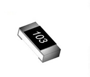
- " Standard Marking 103": The first two digits "10" represent the base value. The third digit "3" denotes "×10³", meaning 10×10³=10,000Ω (10kΩ).
- High-Precision Marking "1002": The first three digits "100" represent the base value, while the fourth digit "2" denotes "×10²", meaning 100×10²=10,000Ω (10kΩ). This marking is commonly found on resistors with a ±1% tolerance.

Note: Avoid confusion with "000": The "000" marking denotes a zero-ohm resistor (short jumper), not a 10k resistor. Misuse may cause circuit short circuits.
Common Package Specifications
Surface-mount components employ a dual "Imperial-Metric" marking system. Core parameters include length (L), width (W), height (H), and pin-related dimensions (a, b). Different specifications vary significantly in terms of volume and power handling capacity, requiring precise selection based on specific application scenarios. Specifications are detailed in the table below:
|
Imperial (inch) |
Metric (mm) |
Length L (mm) |
Width W (mm) |
Height H (mm) |
a (mm) |
b (mm) |
|
0201 |
0603 |
0.60±0.05 |
0.30±0.05 |
0.23±0.05 |
0.10±0.05 |
0.15±0.05 |
|
0402 |
1005 |
1.00±0.10 |
0.50±0.10 |
0.30±0.10 |
0.20±0.10 |
0.25±0.10 |
|
0603 |
1608 |
1.60±0.15 |
0.80±0.10 |
0.40±0.10 |
0.30±0.20 |
0.30±0.20 |
|
0805 |
2012 |
2.00±0.20 |
1.25±0.15 |
0.50±0.10 |
0.40±0.20 |
0.40±0.20 |
|
1206 |
3216 |
3.20±0.20 |
1.60±0.10 |
0.55±0.10 |
0.50±0.20 |
0.50±0.20 |
|
1210 |
3225 |
3.20±0.20 |
2.50±0.20 |
0.55±0.10 |
0.50±0.20 |
0.50±0.20 |
|
1812 |
4832 |
4.50±0.20 |
3.20±0.20 |
0.55±0.10 |
0.50±0.20 |
0.50±0.20 |
|
2010 |
5025 |
5.00±0.20 |
2.50±0.20 |
0.55±0.10 |
0.60±0.20 |
0.60±0.20 |
|
2512 |
6432 |
6.40±0.20 |
3.20±0.20 |
0.55±0.10 |
0.60±0.20 |
0.60±0.20 |
SMD Resistor Specific Parameters (Example: 10kΩ)
Correlation Between Package, Power Rating, and Application Scenarios
SMD resistor packages are named by their "length × width" dimensions. Each package type has clearly defined power limits and application scenarios, requiring matching based on device size and power consumption requirements:
- 0402 (1.0mm × 0.5mm):1/16W power rating, extremely compact size, suitable for miniature devices with stringent space constraints such as mobile phones, smartwatches, and other portable electronics.
- 0603 (1.6mm × 0.8mm):1/10W power rating, a versatile package with strong compatibility, commonly used in routers, sensor modules, small consumer electronics, and other standard applications.
- 0805 (2.0mm × 1.2mm):1/8W power rating. Offers superior thermal performance compared to the 0603 package and enhanced tolerance to temperature fluctuations. Suitable for applications demanding high stability, such as automotive electronics and industrial control boards.
Precision Series and Marking Rules
SMD resistors primarily fall into two precision series: E24 and E96. Their marking methods differ, requiring selection based on circuit precision requirements:
- E24 Series: Accuracy grade ±5%, a general-purpose specification with concise marking. For example, a 10kΩ resistor is marked as "103" ("10" represents the significant digit, "3" denotes the multiplier 10³—i.e., 10 × 10³ = 10000Ω = 10kΩ). This is suitable for standard circuits with moderate precision requirements, such as voltage division in power supplies or simple signal control.
- E96 Series: Accuracy grade ±1%, a precision specification with a four-digit marking. For a 10kΩ resistor, the marking is "1002" ("100" is the significant digit, "2" indicates a multiplier of 10², i.e., 100 × 10² = 10000Ω = 10kΩ). This is suitable for precision circuits such as instrumentation, sensor signal acquisition, and high-frequency communication modules.
Real circuit examples for 10k resistors: From theory to application
The practicality of 10k resistors is evident in various classic circuits. Below are three high-frequency application scenarios with schematic analyses:
Arduino Voltage Divider Circuit (NTC Temperature Detection)
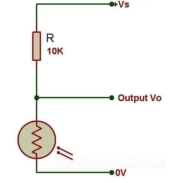
- Circuit Composition: 10k fixed resistor + NTC thermistor (10k@25℃) connected in series, linking Arduino's A0 pin to GND;
- Working Principle: The resistance value of the NTC thermistor decreases as temperature increases, causing the voltage at the divider junction to change. The Arduino reads the voltage at pin A0 and calculates the current temperature.
- Key Function: The 10k fixed resistor serves as the voltage divider arm, ensuring the voltage change range matches the Arduino's 0-5V analog input.
GPIO Pull-Up Resistor Circuit
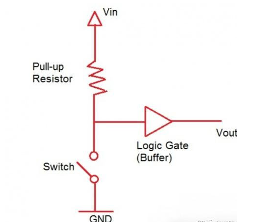
- Circuit Components: One end of the 10k resistor is connected to VCC (3.3V/5V), while the other end connects to the microcontroller's GPIO pin and one side of the button. The other side of the button is connected to GND.
- Functionality: When the button is not pressed, the GPIO pin is connected to VCC through the 10k resistor, maintaining a high logic level. When pressed, the pin grounds to GND, resulting in a low logic level. The microcontroller detects this level change to recognize button presses.
- Key Function: Prevents "level drift" caused by floating GPIO pins, ensuring signal stability and reliability.
NTC/analog sensor Bias Circuit (LED river)
![]()
- Circuit composition: One end of a 10k resistor is connected to the microcontroller's GPIO pin, while the other end is connected to the base (B) of an NPN transistor. The transistor's emitter (E) is connected to GND, and the collector (C) is connected to the LED and a current-limiting resistor before being connected to VCC.
- Operating Principle: When the GPIO outputs a high level, the 10k resistor limits the base current, saturating the transistor and causing the LED to illuminate. When the output is low, the transistor turns off, and the LED extinguishes.
- Key Function: The 10k resistor controls the base current, preventing excessive current from damaging the microcontroller MCU pins or the transistor.
Crucial Steps to Avoid Pitfalls
Whether screening before soldering or troubleshooting after soldering, testing and verification are crucial for ensuring circuit functionality. The specific process is as follows:
Before welding Testing(Screening Qualified Components)
- Visual Inspection: Through-hole resistors must have clear, undamaged color bands. Surface-mount resistors and chip resistors must have complete markings with no missing parts or deformation.
- Resistance Measurement: Using a multimeter set to the 20kΩ range, the measured value must fall within the tolerance range (e.g., for a 10k resistor with ±5% tolerance, the estimated value should be between 9.5kΩ and 10.5kΩ).
- Power rating verification: Select based on circuit power requirements (e.g., 1/4W resistors for currents ≤ 5 mA, 1/2W for currents ≤ 7 mA).
After on-board Testing (Troubleshooting Circuit Faults)
- In-Circuit Measurement: If the circuit fails to function as expected after power-up, disconnect power and measure the resistance across the 10k resistor. A reading of "0Ω" (short circuit) or "infinity" (open circuit) indicates poor soldering or resistor damage.
- Voltage measurement: With power applied, measure the voltage across the resistor terminals. Calculate the current using Ohm's Law (I = U/R) to verify if it meets the design specifications (e.g., a 10k resistor should draw 0.5 mA at 5V across its terminals).
Common Failure Causes
- Excessive resistance deviation: Use of low-precision resistors (e.g., ±10%) or prolonged operation in high-temperature environments, causing resistance drift.
- Open circuit failure: Soldering at excessively high temperatures (above 260°C), or circuit current exceeding the resistor's rated power (e.g., a 1/4W resistor continuously carrying 10mA will burn out due to overheating).
10k Resistor Replacement and Selection Guide: Precisely Matching Requirements
When replacing or selecting a 10k resistor, comprehensively evaluate four dimensions—accuracy, power rating, packaging, and environmental adaptability—to avoid a one-size-fits-all approach:
When tolerance matters (1% vs 5%)
- ±5% accuracy (four-band color code): Suitable for LED current limiting, standard voltage division, pull-up/pull-down applications, and other scenarios without high precision requirements. Lower cost.
- ±1% Accuracy (Five-Band / SMD E96 Series): Suitable for sensor signal processing, precision instruments, industrial control, and other applications demanding high resistance stability, with slightly higher cost.
Wattage Selection: Calculate based on the actual current
Resistor rated power must satisfy "actual power ≤ 0.7 × rated power" (allowing sufficient safety margin). Calculation formula: P = I²R (where I is the actual circuit current). Example using a 10k resistor:
- If circuit current is 5mA, actual power P = (0.005)² × 10,000 = 0.25W, requiring a ≥1/4W resistor;
- If the current is 10mA, the actual power P = (0.01)² × 10,000 = 1W, requiring a resistor rated at ≥1W.
Package Selection: Balancing Installation Scenarios and Manufacturing Processes
- High-density PCBs (mobile phones, drones, smart wearables): Prioritize surface-mount packages (0402, 0603, 0805, etc.) for compact size and high integration, maximizing PCB space utilization. Soldering typically involves reflow soldering (for mass production) or the use of hot-air guns (for small-batch output or repairs).
- Through-Hole PCBs (Industrial grade, High-Power Supplies): Select the AXIAL series through-hole packages (AXIAL-0.4, AXIAL-0.6, AXIAL-0.8) for easy installation and manual soldering capability, which is suitable for high-current/high-power applications.
- Breadboard Experimentation: Select only AXIAL series packages with a 0.1-inch (2.54mm) pin pitch (AXIAL-0.5, AXIAL-0.6, AXIAL-0.8) to ensure that the pins directly fit the breadboard sockets, preventing misuse due to mismatched spacing.
Environmental Adaptability Selection: Addressing Complex Scenarios
Different operating environments impose varying demands on resistor temperature tolerance, moisture resistance, and high-frequency performance. Select components accordingly:
- High-Temperature Environments (Automotive Engine Compartments, Industrial Oven Vicinity): Select metal film resistors with a temperature range of -55°C to 155°C. Their stability surpasses that of carbon film resistors (-40°C to 125°C), preventing resistance drift or component damage at elevated temperatures.
- Humid Environments (Outdoor Surveillance Equipment, Aquaculture Controllers): Opt for resistors with moisture-proof coatings to block vapor, prevent pin oxidation, and stabilize resistance values, thereby extending service life.
- High-frequency circuits (RF modules, wireless communication devices): Select metal film resistors with excellent high-frequency characteristics to minimize signal transmission attenuation and interference, thereby ensuring high-quality circuit communication.
Common Mistakes: Avoid These Mistakes!
Beginners often overlook details when using 10k resistors, which can lead to circuit failures. Here are three common pitfalls and how to avoid them:
Reading Backwards
- Error Manifestation: Misreading the four-band color code "Brown-Black-Orange-Gold" as "Gold-Orange-Black-Brown," resulting in an incorrect resistance value of 0.031Ω.
- Prevention: Always remember the "tolerance band (gold/silver/brown) must be last." If uncertain, verify with a multimeter measurement.
Confusing Brown and Red Bands
- Error Manifestation: Misreading the "red" band (×10²) in the five-band code "Brown-Black-Black-Red-Brown" (10k±1%) as "brown" (×10¹), resulting in a resistance value of 1kΩ;
- Prevention Method: Use a color chart for Comparison (brown appears darker, red appears brighter), or opt for resistor storage boxes with color-coded rings to minimize visual errors.
Misuse of SMD "000" Short Jumper
- Error Manifestation: Using a zero-ohm resistor marked "000" as a 10k resistor, causing a circuit short-circuit and chip burnout;
- Prevention: In SMD resistor markings, "103" denotes 10kΩ, while "000" is solely for circuit jumpers. Store these separately during procurement.
Where to Buy 10k Resistors?(Procurement Guide)
Selecting a reliable supplier is crucial to ensuring the quality of 10k resistors. As a professional electronic component distributor, Unikeyic Electronics provides the following procurement support:
Recommended Specifications and Part Numbers
- Through-hole 10k resistor: Part numbers " MFR0W4F1002A50 " (five-band color code, ±1% tolerance, 1/4W, metal film), suitable for precision circuits;
- SMD 10k Resistor: Part Number " 0805W8J0103T5E " (0805 package, ±5% tolerance, 1/8W), general-purpose specification;
Procurement Advantages
- Quality Assurance: All resistors are factory-authorized, RoHS compliant, with material certificates and factory test reports provided.
- Ample Inventory: Both through-hole and surface-mount specifications are in stock, supporting bulk purchasing.
- Technical Support: Selection consultation available; recommend suitable precision, power rating, and package based on circuit requirements.
FAQ:
What's the difference between 4-band and 5-band 10k resistors?
The core difference lies in precision and color band count: four-band resistors offer ±5% accuracy (three value bands + one tolerance band), while five-band resistors provide ±1% accuracy (four value bands + one tolerance band). The additional value band in five-band resistors enhances resistance resolution, making them suitable for precision applications.
Can I replace a 10k resistor with another value?
This depends on the circuit function: For pull-up/pull-down or standard voltage division, substitution within ±20% tolerance is acceptable (e.g., using 8.2k or 12k resistors). However, for sensor signal processing or precision voltage division, the use of 10k resistors is strictly required to prevent measurement errors or functional failure.
Why is the 10k resistor commonly used in electronics?
Its resistance value suits most circuit current requirements: at a 5V supply voltage, a 10k resistor handles 0.5mA current. This avoids weak signals from insufficient current while preventing component burnout from excessive current, serving as a balanced "middle ground" between performance and safety.
Are 10k SMD resistors marked differently?
Yes. SMD resistors use numerical codes instead of color bands. The standard tolerance (±5%) is marked as "103" (10 × 10³), while the high tolerance (±1%) is marked as "1002" (100 × 10²). These codes have no color-related indicators and must be interpreted using the numerical system.
Summary
Color band coding for 10k ohm resistors is the "foundational language" for electronics engineers. Mastering its reading rules, application scenarios, and selection techniques is key to efficiently completing circuit design and maintenance. If you're a novice or a seasoned professional, please note that color band readings must be verified with a multimeter, and the selection must match the precision, power rating, and environmental requirements to prevent circuit failures due to overlooked details.
For further exploration of electronic component knowledge, stay tuned to the unikeyic Tech Blog for practical guides and industry updates on resistors, capacitors, inductors, and more. Ensure project success with high-quality components and professional expertise.