Arduino Hands-on - Infrared Line Tracking Sensor
The reflex photoelectric switch, also belonging to the category of infrared invisible light products, is a type of small photoelectric component that can detect changes in the intensity of light it receives. Initially used to detect the presence or absence of objects, it consists of an infrared emitter and an infrared receiver combined. The emitter has a wavelength of 780nm-1mm and comes with a calibration lens to focus the light towards the receiver. The receiver sends the signal through a cable to be connected to a vacuum tube amplifier. The detection occurs between the emitter and detector in the gap between the slotted switch and the bulk optic path when an object enters. As the object approaches the detection zone, part of the light collected by the receiver is reflected onto the photoelectric element. By utilizing the object's obstruction or reflection of the infrared light beam, the synchronous circuit is activated to detect the presence of the object. This detection is not limited to metallic objects; it can identify any object capable of reflecting light.
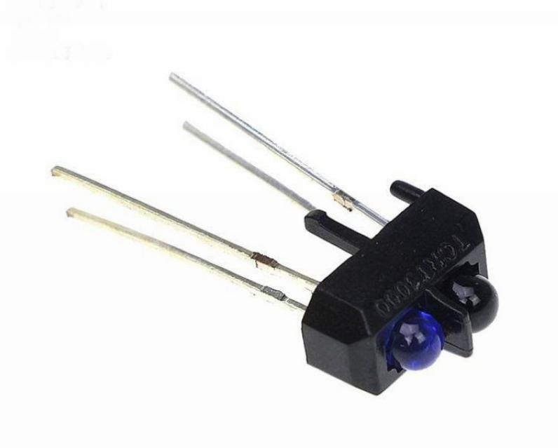
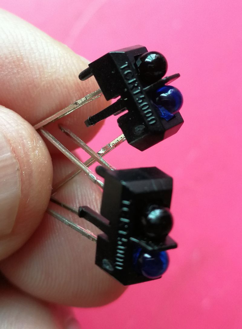
The TCRT5000operates on the same principle as general infrared sensors. It consists of an infrared emitter and an infrared receiver. When the infrared signal emitted by the emitter is reflected and received by the receiver, the resistance of the receiver changes. This change is typically manifested as a voltage variation in the circuit. The processed output result is obtained after ADC conversion or shaping by circuits like LM324. The variation in resistance is dependent on the intensity of the infrared signal received by the receiver, which is often influenced by both the color of the reflecting surface and the distance between the reflecting surface and the receiver.
Work Environment
+: Connect to positive pole of DC 5V
-: Connect to negative pole of DC 5V
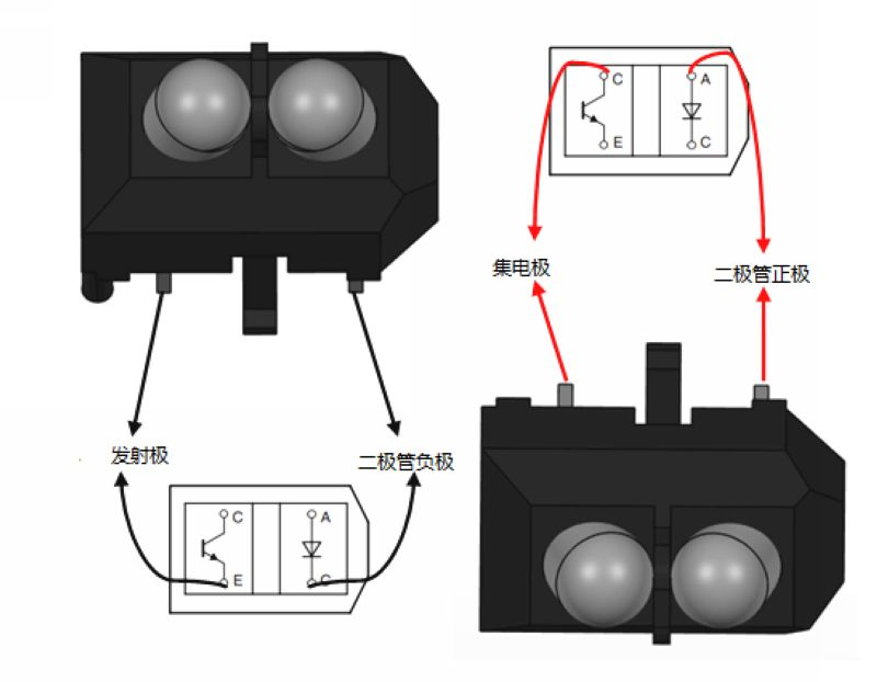
S: Signal output terminal, the phototransistor is saturated. At this time, the output terminal of the module is at a high level, indicating that the diode is illuminated.
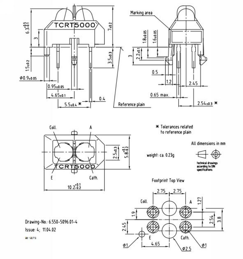
Operating voltage: DC 3V~5.5V, recommended operating voltage is 5V
Detection distance: Suitable for 1mm~8mm, with a focal distance of 2.5mm
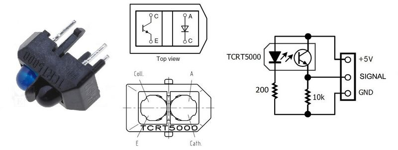
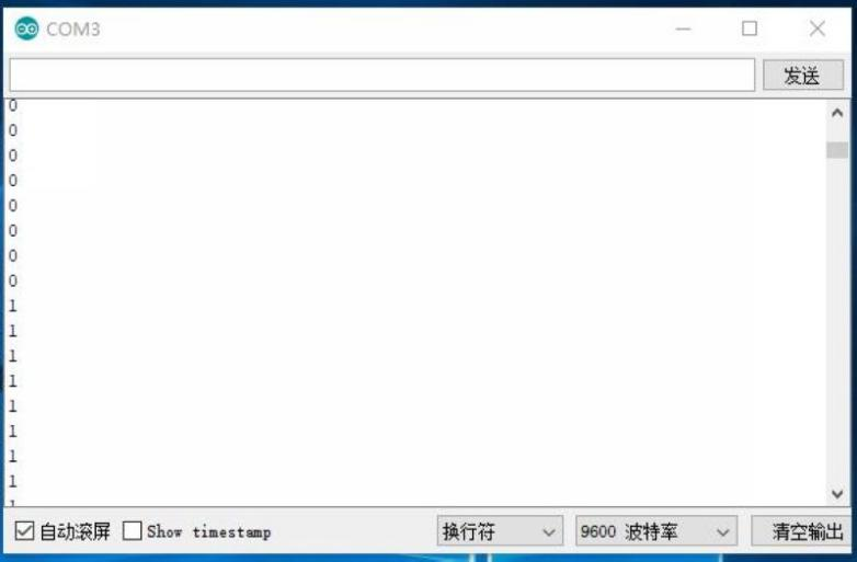
The infrared emitting diode of TCRT5000 continuously emits infrared light. When the emitted infrared light is not reflected back or is reflected back but with insufficient intensity, the photosensitive transistor remains in the off state. At this time, the output terminal of the module is at a low level, indicating that the diode is always in the off state; when the detected object appears within the detection range, the reflected infrared light is strong enough, causing the photosensitive transistor to saturate. The output terminal of the module is at a high level, indicating that the diode is lit up.
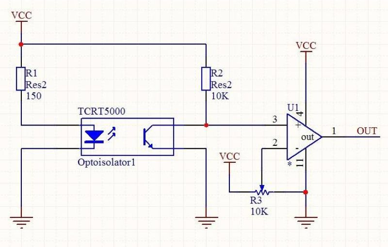
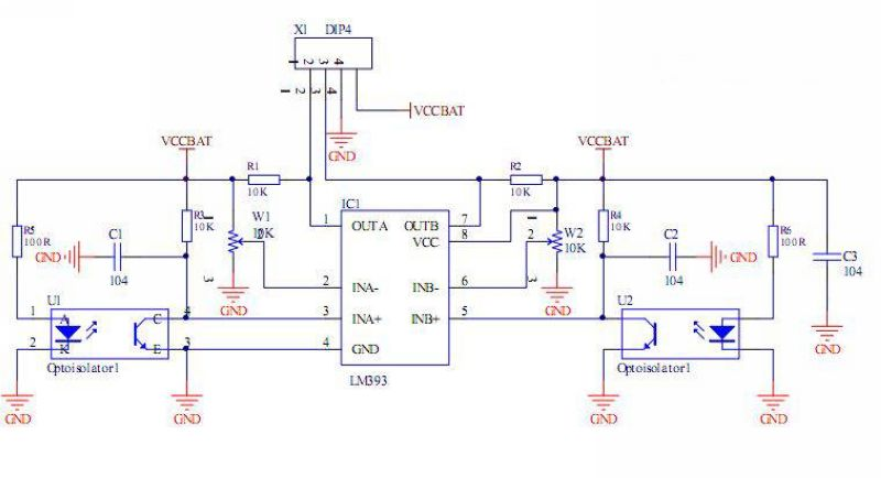
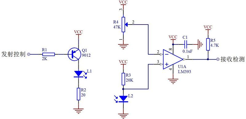
Several application circuits for TCRT5000 sensor.
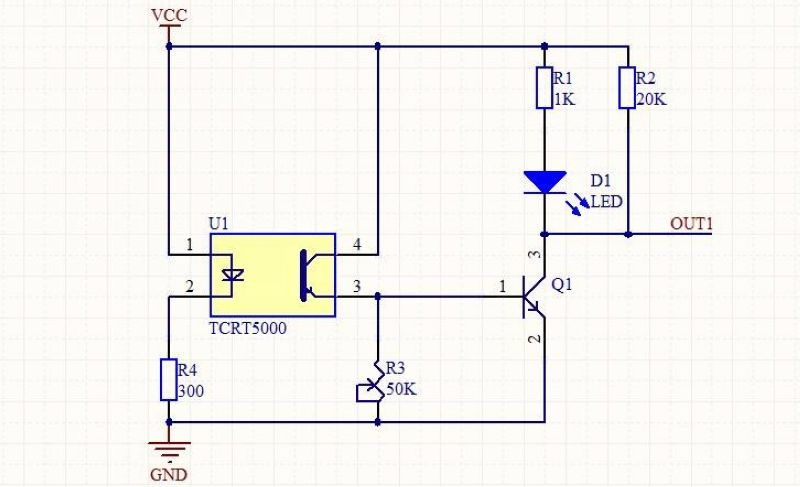
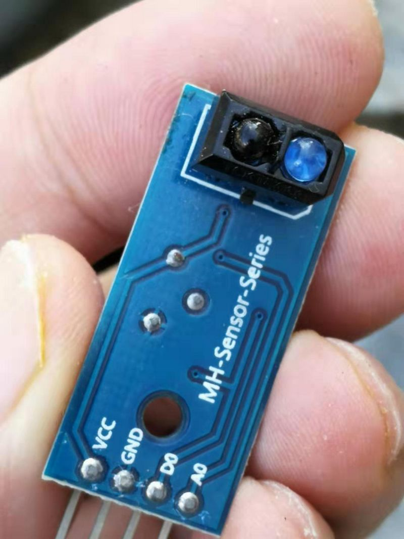
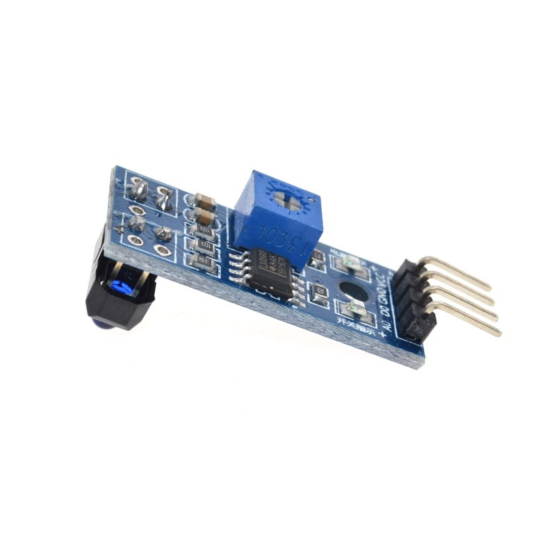
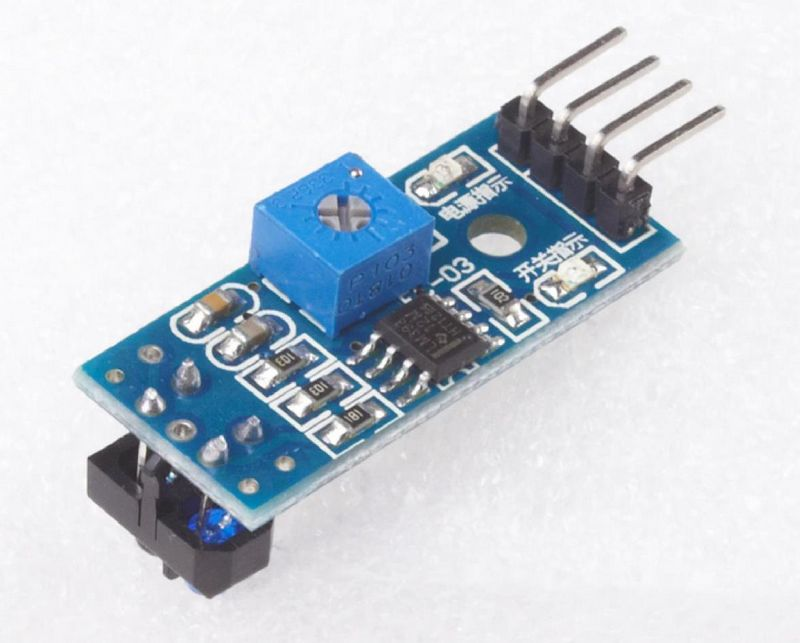
TCRT5000 Infrared Reflective Optoelectronic Switch Tracking Sensor Module
Utilizes TCRT5000 infrared reflective sensor.
Detects reflection distance of 1mm to 25mm.Comparator output with clean signal, good waveform, and strong driving capability exceeding 15mA.Equipped with multi-turn adjustable precision potentiometer for sensitivity adjustment.Operating voltage: 3.3V-5V.Output form: digital switch quantity output (0 and 1).Features fixed bolt holes for easy installation.Small PCB size: 3.2cm x 1.4cm.Uses wide voltage LM393 comparator.
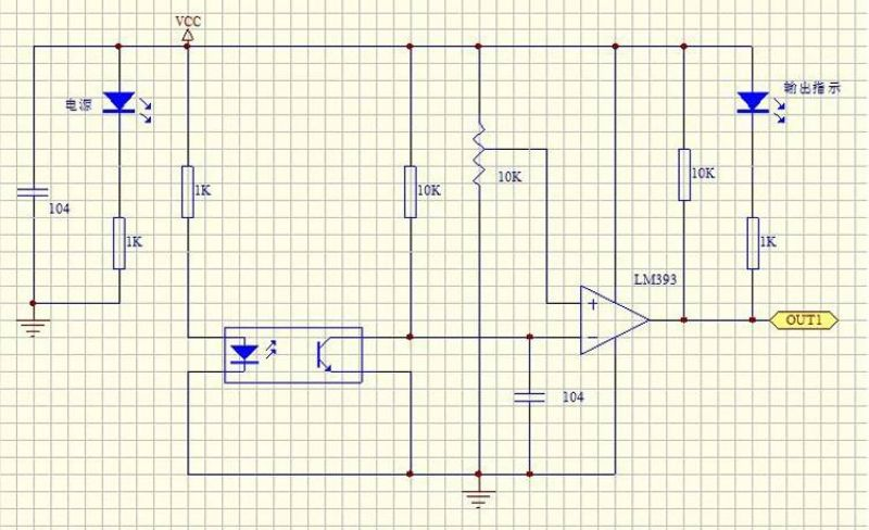
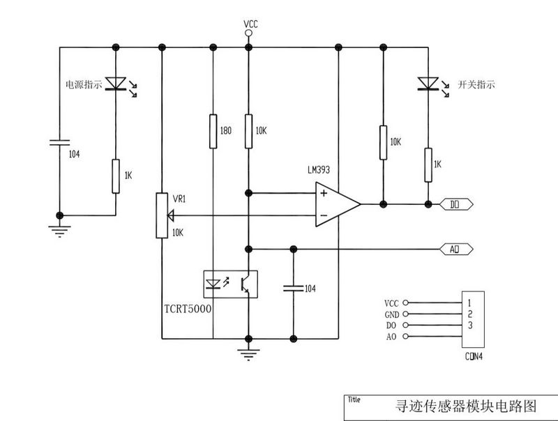
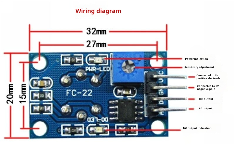
Schematic diagram of the module
Module Description
This sensor module has strong adaptability to ambient light. It consists of a pair of infrared emitting and receiving tubes. The emitting tube emits infrared rays at a certain frequency. When the detection direction encounters an obstacle (reflective surface), the infrared rays are reflected back and received by the receiving tube. After being processed by the comparator circuit, the green indicator light will illuminate. At the same time, the signal output interface outputs a digital signal (a low-level signal). The detection distance can be adjusted through a potentiometer, with an effective range of 2 to 30 cm. The working voltage ranges from 3.3V to 5V. This sensor features adjustable detection distance via a potentiometer, low interference, easy assembly, and convenient usage. It can be widely used in applications such as pulse data sampling for electricity meters, paper detection for fax machines and shredders, counting on assembly lines, obstacle avoidance for robots and vehicles, as well as black and white line tracking, among many other scenarios.
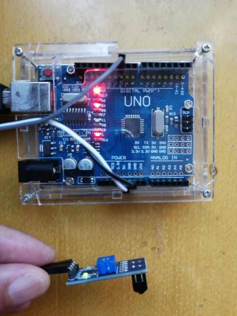
Module Wiring Instructions
VCC: Connect to positive terminal of power supply (3-5V).GND: Connect to negative terminal of power supply.
DO: TTL switch signal output.
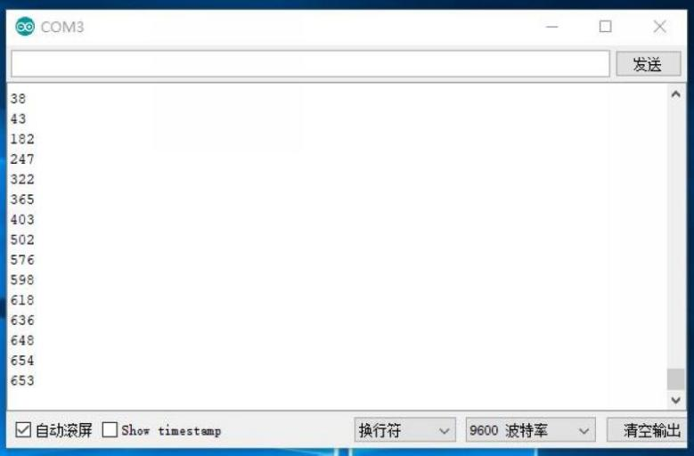
AO: Analog signal output (output different voltages depending on the distance, this pin can generally be left unconnected).
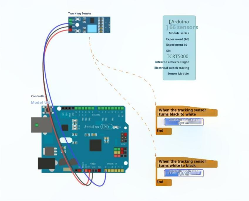
Experiment with open-source graphical programming
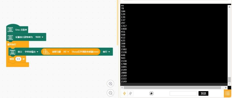
Experimental open-source simulation programming