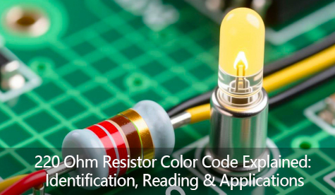
220 Ohm Resistor Color Code Explained: Identification, Reading & Applications
220-ohm resistors can be quickly identified by their color bands: a four-band code of "Red-Red-Brown-Gold" indicates ±5% tolerance, while a five-band code of "Red-Red-Black-Black-Brown" indicates ±1% tolerance. Accurate reading requires using the tolerance band (gold or silver) as the reference, and must be verified with a multimeter to confirm the resistance value falls within the normal range. Its core value lies in ensuring safe and stable circuit operation through current limiting and voltage division. It is typically used in led driver protection, voltage distribution, and microcontroller signal conditioning, serving as an indispensable fundamental component in electronic circuits.
What Is a 220 Ohm Resistor?
● Definitions and Basic Functions
Definition:
A 220-ohm resistor, as the name suggests, is an electronic component with a resistance value of 220 ohms (Ω). The ohm is the standard unit of resistance in the International System of Units (SI), defined as follows: When a voltage of 1 volt (V) is applied across a resistor and it produces a current of 1 ampere (A), the resistance of that resistor is 1 ohm. Therefore, a resistor with a nominal value of 220 ohms, following Ohm's Law (V = I × R), exhibits a specific, fixed resistance to the flow of current as its core characteristic. For example, applying a 3.3V voltage across its terminals will theoretically produce a current of approximately 15 milliamps (I = V / R = 3.3V / 220Ω ≈ 0.015A). Resistors come in various physical forms, such as axial leaded resistors with color bands (typically red, red, brown, gold) or surface-mount resistors. They are widely used in electronic designs ranging from simple circuits to complex devices.
Basic Functions:
The fundamental functionality of a 220-ohm resistor stems from the universal properties of resistors, yet its specific resistance value makes it the "gold standard" or common choice in certain applications. Its primary functions can be summarized as follows:
● Current Limiting and Protective Components:
This is the most classic and widespread application of a 220-ohm resistor. The most typical example is driving light-emitting diodes (LEDs). LEDs are current-driven devices. Once their operating voltage (typically 2-3V) is exceeded, their internal resistance becomes extremely low. Without external limitation, the current will surge dramatically until the device burns out. Connecting a 220-ohm resistor in series with the LED effectively limits the current in the circuit. For example, in a 5V circuit, assuming the LED voltage drop is 2.2V, the resistor must handle a voltage drop of 2.8V. According to Ohm's Law, the current I = (5V - 2.2V) / 220Ω ≈ 12.7mA. This current level is entirely safe for most standard LEDs. Thus, the 220-ohm resistor serves as an indispensable "guardian" in this circuit.
● Pull-up or pull-down resistor:
In digital circuits, the input pin state (high or low) of microcontrollers (such as Arduino or STM32) must be clearly defined. When a pin is connected to a switch or button, it remains floating and in an undefined state when the switch is open, making it highly susceptible to false triggering due to external electromagnetic interference. In such cases, a 220-ohm resistor can function as either a pull-up resistor (connected to the positive power supply) or a pull-down resistor (connected to ground). When the switch is open, this resistor provides the pin with a clear, stable high or low level, ensuring the circuit's logical stability. While 10kΩ is a commonly used value, smaller resistances like 220Ω are frequently employed in applications requiring stronger drive capability and faster response times.
● Voltage Divider Function:
When two resistors are connected in series, they can form a voltage divider circuit. A 220-ohm resistor can be combined with resistors of other values to derive a lower, specific voltage from a higher input voltage, supplying power to other circuit sections or serving as a reference voltage. While it may not be the optimal choice for precision voltage division applications, it is perfectly adequate for scenarios where high accuracy is not required.
● Impedance Matching and Signal Conditioning:
In simple signal transmission paths, low-resistance components (such as 220 ohms) are sometimes used to slightly attenuate signal amplitude. Alternatively, they may interact with line capacitance to smooth signal edges, preventing overshoot and ringing, thereby performing preliminary signal conditioning.
● Electrical Characteristics: Resistance Value, Tolerance, Rated Power
For a complete description of a 220-ohm resistor, knowing only its nominal resistance value is far from sufficient. Tolerance and rated power jointly define its capability and reliability in actual circuits. These three elements form its most fundamental electrical characteristic profile. When selecting a 220-ohm resistor, all three characteristics must be comprehensively considered:
Resistance Value: Reveals its "Identity" (220Ω)
Resistance value quantifies a resistor's opposition to current flow, measured in ohms (Ω). 220Ω represents its design resistance value under ideal conditions. This figure is printed on the resistive element or indicated by color bands (typically red-red-brown). Resistance values are not absolute. They fluctuate due to factors like temperature, humidity, operating time, and applied power. A high-quality resistor exhibits superior resistance stability.
Tolerance: Telling You Its "Precision"
Tolerance, also known as accuracy, indicates the maximum permissible deviation range of a resistor's actual resistance value relative to its nominal resistance value. The most common tolerance grades for 220Ω resistors are ±5% (typically indicated by a gold band) and ±1% (typically indicated by a brown band). Tolerance selection depends on circuit requirements. For applications like LED current limiting or pull-up/pull-down circuits where precise current and voltage are less critical, ±5% tolerance is sufficient and more cost-effective. However, precision amplifier circuits, voltage dividers, or measurement circuits require resistors with ±1% or tighter tolerances to ensure circuit accuracy and consistency.
Rated Power: Tells you its maximum "stamina" limit
Rated power refers to the maximum power value a resistor can dissipate while operating safely and reliably over extended periods, measured in watts (W). When current flows through a resistor, electrical energy is dissipated as heat, calculated as P = I² × R or P = V² / R. This is a critical parameter when selecting resistors, directly determining whether the resistor will overheat and burn out. For a 1/4W 220Ω resistor, the maximum voltage it can withstand is: V = √(P × R) = √(0.25 × 220) ≈ 7.4V. The maximum safe current is: I = √(P / R) = √(0.25 / 220) ≈ 33.7mA.
If the applied voltage or calculated power dissipation in the circuit exceeds these limits, a higher-power resistor (e.g., 1/2W) must be selected, or the circuit design must be modified to reduce power dissipation.
● Common Package Types(Axial / SMD)
220-ohm resistors are primarily available in two major package types:Axial and SMD.
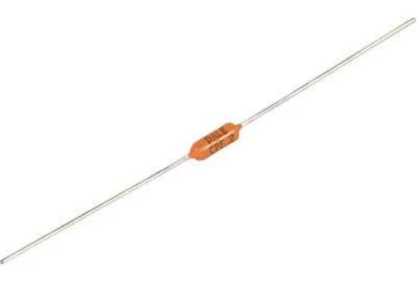
Axial
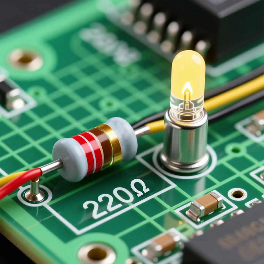
Axial leaded packages, also known as axial packages, feature a resistive element with two axial leads extending from each end, resembling "legs." The most iconic example of this package is the cylindrical resistor with color bands, where the "Red-Red-Brown" band sequence indicates a 220-ohm resistance value. Primarily used in through-hole technology, it is commonly found in breadboard soldering, DIY projects, and early electronic devices due to its ease of manual installation and replacement.
SMD
Surface Mount Device (SMD) This is the absolute mainstream in modern electronics manufacturing. SMD resistors are chip components without long leads, mounted directly onto the circuit board surface and soldered via reflow soldering. Their dimensions are represented by standardized codes, such as:
0805: Length 2.0mm, width 1.2mm, relatively universal.
0603: 1.6mm long, 0.8mm wide, used for high-density boards.
0402 and smaller sizes: Used in microdevices like smartphones.
Resistance values are typically printed as alphanumeric codes on the top of the component. SMD packaging significantly saves space, is suitable for fully automated production, and is the preferred choice for current mass manufacturing..
Understanding the Resistor Color Code
● Introduction to the Resistor Color Band System(4-band, 5-band, 6-band)
The resistor color band system is a color-coded ring pattern printed on the axial lead resistor body, providing an intuitive representation of the resistor's resistance value and tolerance. This serves as an efficient, low-cost method for parameter identification when components are too small to accommodate direct numerical printing.
This system employs a color-to-number mapping, where each color corresponds to a specific numerical value. By reading the numerical values represented by color bands at different positions and combining them according to established rules, the resistance value can be determined. Common types include four-band, five-band, and six-band resistors.
● The numerical values represented by color bands and their tolerance meanings
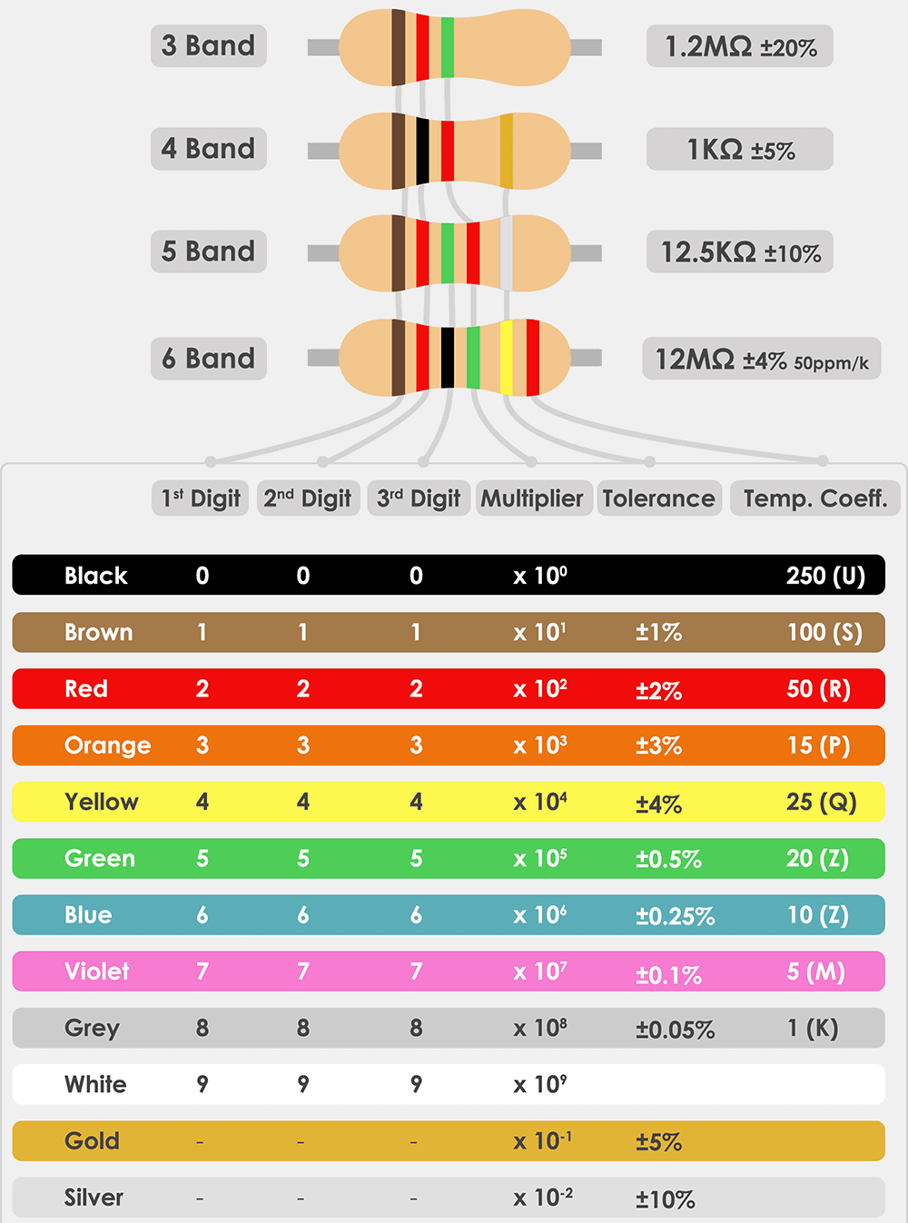
In four-band resistors, the first two bands represent significant figures, the third band indicates the multiplier, and the fourth band denotes the tolerance class. Widely used in electronic devices, their tolerance is typically ±5% or ±10%.
In five-band resistors, the first three bands represent significant figures, the fourth band indicates the multiplier, and the fifth band denotes the tolerance class. This type offers higher precision (tolerance as low as ±1% or ±2%) and is suitable for precision circuits.
In six-band resistors, the first five bands correspond to those in five-band resistors, while the sixth band indicates the temperature coefficient (ppm/°C). They are primarily used in temperature-sensitive applications such as military and aerospace.
● What color is a 220 ohm resistor?
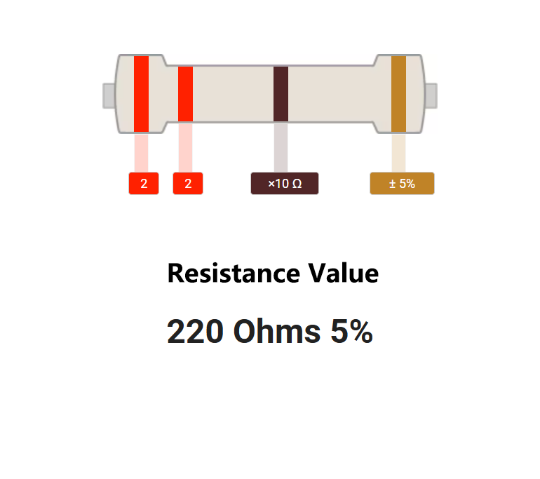
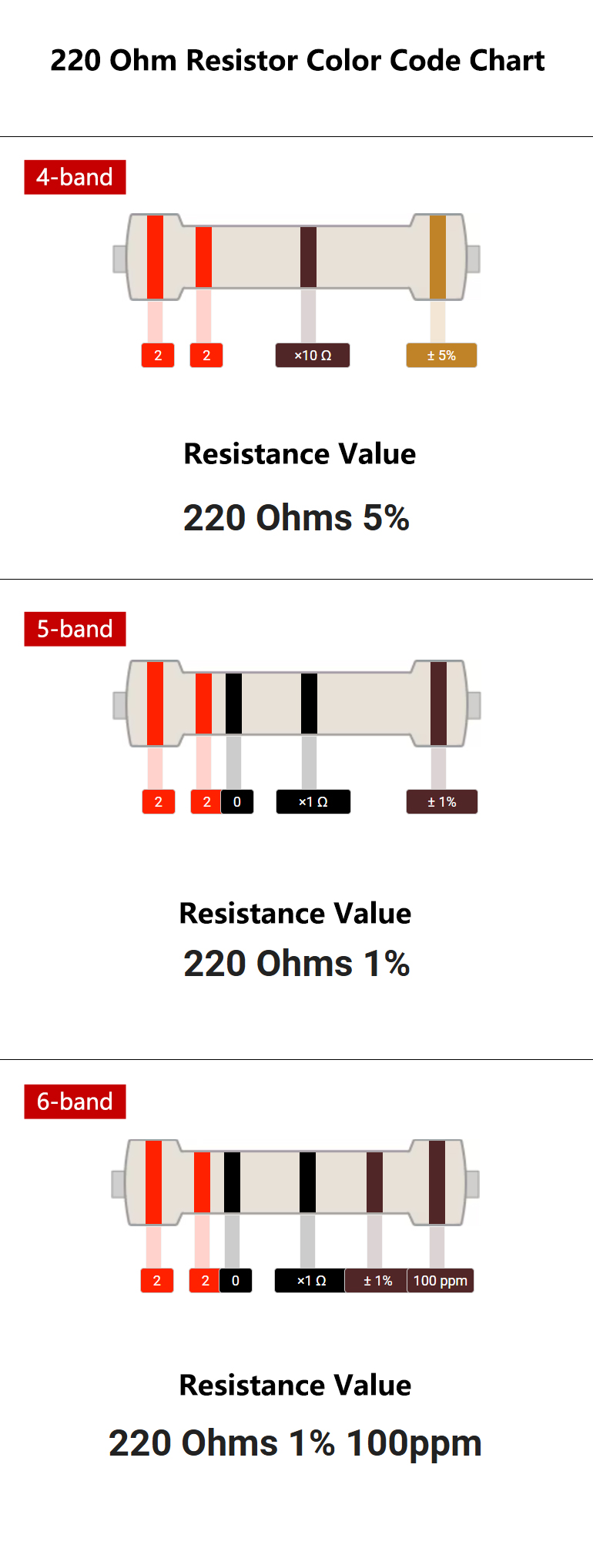
For a 220Ω ±5% resistor, the color band sequence is: Red - Red - Brown - Gold.
The first band, red, indicates the first significant digit. In the color band code chart, red represents the number 2. This gives the first digit of the resistance value.
The second band, red, indicates the second significant digit. Again, red represents the number 2. Combined with the first band, this forms "22".
The third band, brown, indicates the multiplier, representing a multiplier of 10, or ×10. This means we need to multiply "22" by 10, adding one zero, to obtain 220 ohms.
The fourth band, gold, indicates the tolerance. It represents a tolerance of ±5%. This means the actual resistance value of this resistor is acceptable within the range of 209Ω (220 - 5%) to 231Ω (220 + 5%).
220 Ohm Resistor Color Code Chart
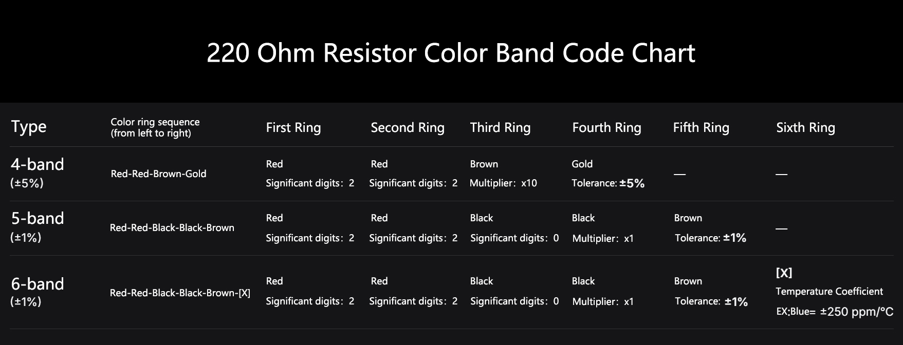
● Table Display (4-Color Ring, 5-Color Ring, 6-Color Ring Comparison)
● Example:
4-band: Red, Red, Brown, Gold = 220Ω ±5%
5-band: Red, Red, Black, Black, Gold = 220Ω ±1%
● What is the color code for a 220 ohm 1W resistor?
This is a very practical question. For a 220-ohm, 1W resistor, the color band coding is primarily determined by its tolerance (accuracy), while the power rating (1W) is typically not directly indicated by the color bands but rather conveyed through the physical dimensions of the resistor.
For a 220-ohm resistance value, the most common color band codes are as follows:
Four-color ring coding (tolerance ±5%)
This is the most common type, with the color band sequence: Red - Red - Brown - Gold
First band (Red): First significant digit 2
Second band (Red): Second significant digit 2
Third band (Brown): Multiplier 10¹ (i.e., ×10)
Fourth band (Gold): Tolerance ±5%
Calculation: 22 × 10 = 220Ω, accuracy ±5%.
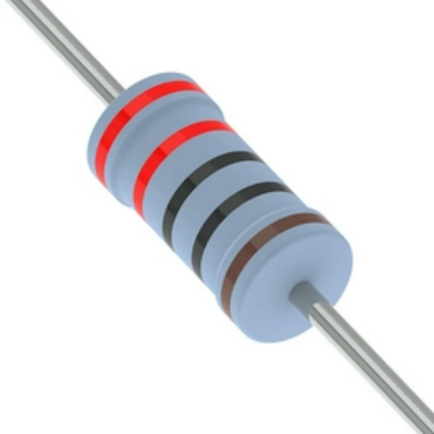
Five-Color Ring Code (Tolerance ±1%)
This type is used for higher precision, with the color band sequence being: Red - Red - Black - Black - Brown>
First band (Red): First significant digit 2
Second band (Red): Second significant digit 2
Third band (Black): Third significant digit 0
Fourth band (black): Multiplier 10⁰ (i.e., ×1)
Fifth band (brown): Tolerance ±1%
Calculation: 220 × 1 = 220Ω, accuracy ±1%.
Power Rating (1W): Definition and Examples
The power rating (1W) represents the physical capacity of a resistor, determining its volume, dimensions, and material composition. A 1W 220Ω resistor will be significantly larger and heavier than a 1/4W 220Ω resistor. You cannot use a 1/4W resistor in a circuit requiring 1W of power consumption, as it will overheat and burn out rapidly.
Combined power example:
Suppose we have a circuit that requires approximately 1W of power consumption. Circuit conditions: Supply voltage V = 15V, The required current I is determined by the resistor R = 220Ω. Power calculation: According to the formula P = V² / R, P = (15V)² / 220Ω = 225 / 220 ≈ 1.02W
Therefore, we conclude that:
In this circuit, the 220Ω resistor must dissipate approximately 1.02W of power.
Correct selection: You must choose a 220Ω resistor rated for 1W (or higher, such as 2W). This resistor will typically be a larger axial resistor with color bands marked as red-red-brown-gold or red-red-black-black-brown.
Physical characteristics: Its length may exceed 10mm, with a diameter of approximately 4-5mm. It may feature a metal heat sink or be a cement resistor.
Wrong Choice: What happens if you mistakenly use a 1/4W 220Ω resistor (with the same color bands: red-red-brown-gold, but much smaller in size)?
This resistor's maximum power rating is only 0.25W, while the circuit actually requires it to dissipate 1.02W.
The resistor will heat up rapidly, far exceeding its cooling capacity. Within seconds to minutes, the resistor will burn out due to overheating, typically exhibiting smoke, blackened color bands, and infinite resistance (open circuit).
How to Read and Verify a 220 Ohm Resistor
Reading and verifying a 220-ohm resistor is a crucial electronic skill, consisting of two steps: first, determine its nominal value by reading the color bands, then verify its actual value using a multimeter.
● Reading Procedure (Position, Orientation, Value Verification)
First, identify the color bands on the resistor and interpret their meaning. A 220Ω resistor typically has two common color codes:
Four-color band (standard tolerance, ±5%): Red - Red - Brown - Gold
Interpretation method: First band (Red): 2, Second band (Red): 2, Third band (Brown): ×10, Fourth band (Gold): ±5%.
Calculation: 2² × 10 = 220Ω, tolerance ±5%. Its actual resistance value is considered acceptable within the range of 209Ω to 231Ω.
Five-color band (high precision, ±1%): Red - Red - Black - Black - Brown
Interpretation method: First band (Red): 2, Second band (Red): 2, Third band (Black): 0,
Fourth band (Black): ×1, Fifth band (Brown): ±1%.
Calculation: 220 × 1 = 220Ω, tolerance ±1%. Its actual resistance value is considered acceptable within the range of 217.8Ω to 222.2Ω.
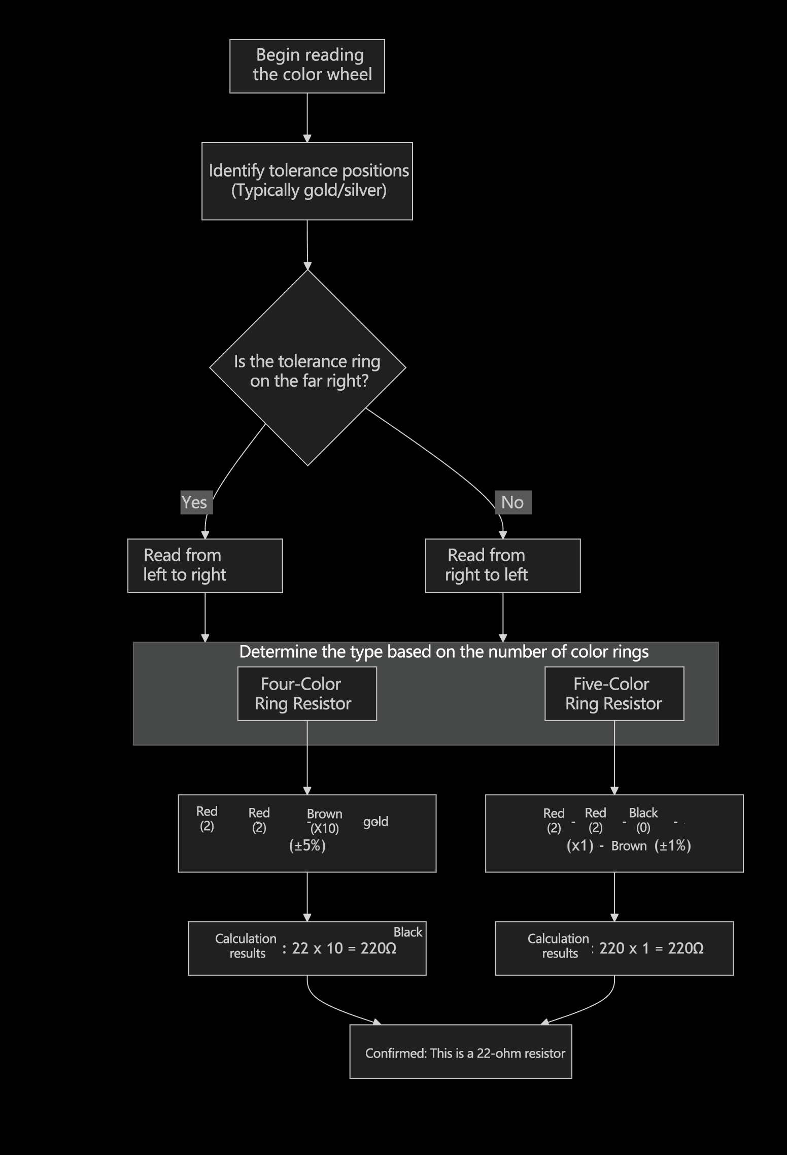
How to determine the reading direction?
Key: Locate the tolerance band (typically gold or silver), which is always positioned last.
Tip: The gap between the tolerance band and the color band at the opposite end is usually wider, or the lead at the end of the resistor is closer to the first band.
The diagram below clearly illustrates the color band interpretation process for two 220Ω resistors, helping you quickly identify them.:
● Use a multimeter to verify the resistance value
After reading the color bands, you must verify the resistor using a multimeter to ensure it is intact and has the correct resistance value.
Operating Steps:
1. Select the correct gear:
Rotate the multimeter to the resistance setting (Ω range). If the approximate resistance value is unknown, start with a wider range (such as 200Ω or 2kΩ) before switching to a more precise range. For 220Ω, either the 200Ω or 2kΩ setting is acceptable.
2. Connecting test leads:
Insert the black test lead into the COM jack of the multimeter. Insert the red test lead into the Ω or VΩ jack.
3. Measure resistance:
Use the multimeter probes to make reliable contact with both leads of the resistor (Note: Do not touch both metal probes simultaneously with your hand, as body resistance will cause inaccurate measurements). Observe the stable reading displayed on the multimeter screen.
4. Interpretation of Results:
Normal condition: The reading should be very close to 220Ω. Considering tolerance, a quad-ring resistor displaying a value between 209Ω and 231Ω is normal.
Reading close to 0Ω: The resistor may have shorted internally and is damaged.
Reading overflow (displays "1" or "OL"): The resistor has burned out internally and is open-circuited.
Reading significantly above or below the normal range: The resistor may have deteriorated and failed, or you may have misidentified the color bands.
Summary and Notes
Comprehensive Assessment: Successful verification indicates that the nominal value read from the color bands matches the actual value measured by the multimeter within reasonable tolerance limits.
Safe Measurement: When measuring, ensure at least one end of the resistor is disconnected from the circuit board (i.e., not in a live circuit). Otherwise, other components in the circuit may interfere with the measurement, leading to inaccurate readings.
Power Observation: For high-power resistors (e.g., 1W, 2W) rated at 220Ω, physical inspection is also advisable. Signs of scorching or cracking indicate likely damage.
By following these two steps—"reading" and "measuring"—you can accurately identify and verify the condition and authenticity of a 220-ohm resistor.
● How to know if a resistor is 220 ohm?
Determining whether a resistor is 220 ohms requires two steps: "preliminary identification" and "final verification." The former involves a quick visual check, while the latter uses tools for precise confirmation.
Step 1: Preliminary Identification - Check the Nominal Value
Quickly identify resistors by their markings based on their type.
1. For leaded resistors (with color bands), this is the most common method.
Locate the color bands on the resistor.
Most common 220Ω resistor (±5% tolerance): Color band sequence: Red - Red - Brown - Gold
Interpretation: Red (2), Red (2), Brown (×10), Gold (±5%) → 22 × 10 = 220Ω
High-precision 220Ω resistor (±1% tolerance): Color band sequence: Red - Red - Black - Black - Brown
Interpretation: Red (2), Red (2), Black (0), Black (×1), Brown (±1%) → 220 × 1 = 220Ω
How to determine the reading direction?
Key point: The tolerance ring (gold or silver) is always in the last position. Place it on your right, then read from left to right.
2. For surface-mount resistors(SMD)
Surface-mount resistors are small black squares printed with numerical or alphabetic codes.
Three-digit code: For 220Ω, the most common code is "221".
Interpretation: The first two digits "22" are significant figures, and the third digit "1" represents 10 to the power of 1 (adding one zero). Thus, 22 × 10 = 220Ω.
Four-digit code (high precision): Could be "2200".
Interpretation: The first three digits "220" are significant figures, and the fourth digit "0" represents 10^0. Thus, 220 × 1 = 220Ω.
E96 Series Code: For more precise resistors, codes like "220" or others may be used, but "221" remains the most universal identifier for 220Ω.
Step2:Final Verification - Measure with a Multimeter
Visual identification is only the first step; resistors may be damaged or mislabeled. Using a multimeter for measurement is the only reliable verification method.
Operating Steps:
Preparation: Ensure at least one end of the resistor is disconnected from the circuit board (or measure a separate resistor directly). Otherwise, interference from other components in the circuit may cause inaccurate measurements.
Select the range: Turn the multimeter to the resistance range (Ω range).
Select Range: If the resistance value is unknown, choose a range slightly larger than 220Ω, such as "200Ω" or "2kΩ".
Connect Probes: Insert the black probe into the COM jack and the red probe into the Ω or VΩ jack.
Perform Measurement: Securely contact both ends of the resistor with the probes (avoid touching both metal ends simultaneously).
Interpreting Results: If the resistor is functional and indeed 220Ω: The multimeter reading will be very close to 220. Consider its tolerance:
For ±5% tolerance resistors, readings between 209Ω and 231Ω are acceptable.
For ±1% tolerance resistors, readings should fall between 217.8Ω and 222.2Ω.
If the resistor is damaged:
Reading is infinite (displays "1" or "OL"): Internal open circuit (burned out).
Reading is close to 0Ω: Internal short circuit (broken down), which is less common.
Reading deviates significantly from the normal range: Resistor has deteriorated and failed.
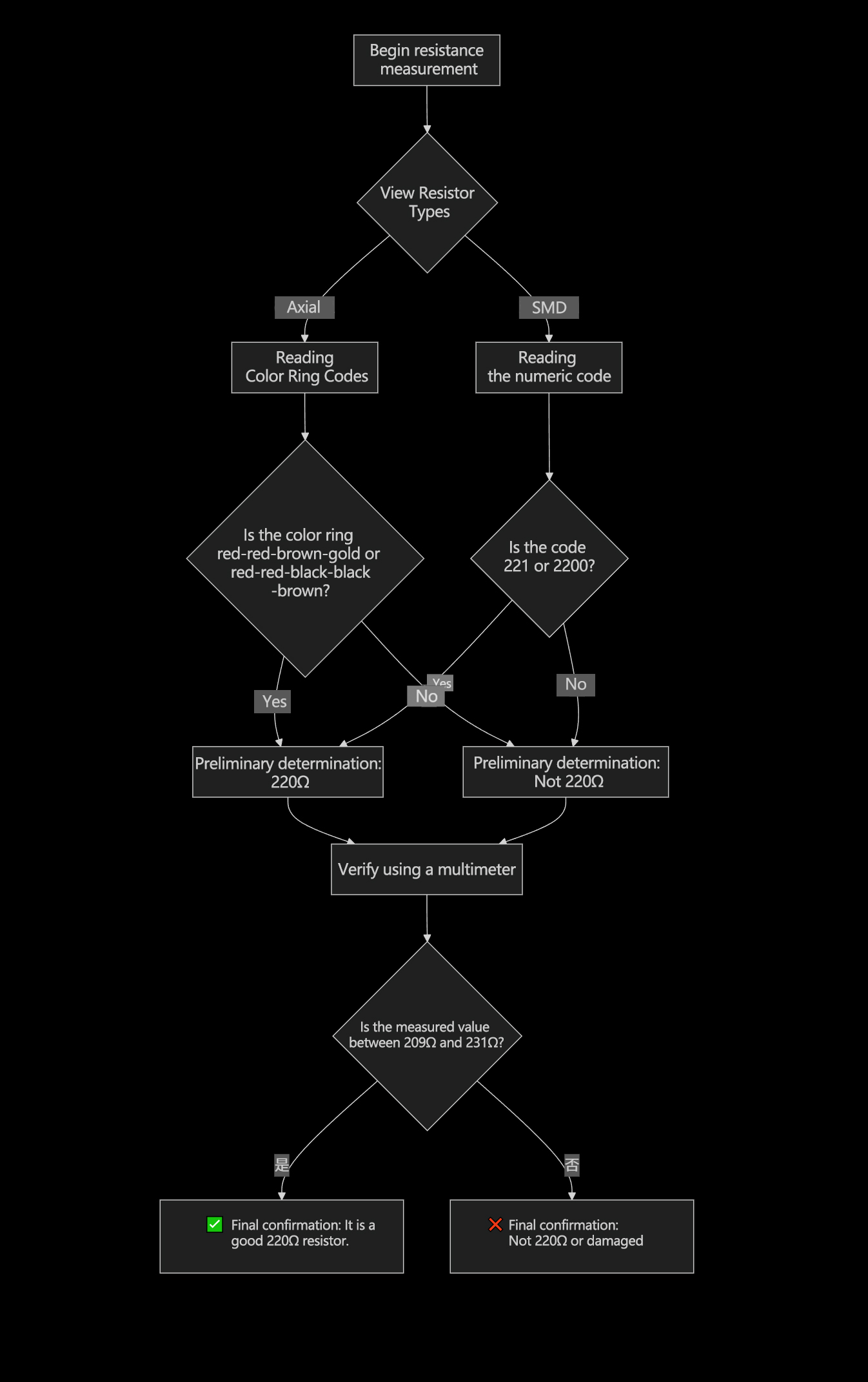
Summary Judgment Process
You can follow the steps shown in the flowchart below to systematically determine whether the resistor is 220 ohms:
Applications of 220 Ohm Resistors
● LED Current-Limiting Resistor (with diagram)
Why do LEDs require current-limiting resistors?
An LED (light-emitting diode) is a current-driven device, meaning its brightness is determined by the magnitude of the current flowing through it. Unlike ordinary resistors, LEDs exhibit a very steep voltage-current characteristic—once the voltage across its terminals exceeds a specific value (the forward voltage drop, typically 2-2.2V), its internal resistance becomes extremely low, causing the current to surge sharply.
If an LED is connected directly to a power source (such as 5V) without a resistor to limit the current, then according to Ohm's Law (I = V / R), the current I will far exceed the LED's maximum current rating (typically 20-30mA) because R is negligible. This will cause the LED to burn out instantly.
Therefore, the function of the current-limiting resistor is to dissipate excess voltage and restrict the current in the circuit, ensuring it remains within the safe operating range of the LED.
Why is 220 ohms often chosen?
Let's calculate using a typical example. This is a very common scenario. Assume the circuit parameters are as follows:
Supply voltage (V_s): 5V (e.g., USB power supply or the 5V pin on an Arduino)
LED forward voltage drop (V_f): Approximately 2.2V (this is the typical value for most standard red, green, and yellow LEDs)
Expected operating current (I): Approximately 20mA (0.02A) (This is a safe current value that provides sufficient brightness)
The calculation process is as follows:
Calculate the voltage (V_R) the resistor must bear
The resistor must bear the power supply voltage minus the LED's own voltage drop.
VR = Vs - Vf = 5V - 2.2V = 2.8V
Calculate the required resistance value (R)
According to Ohm's Law, R = V / I, we divide the voltage that the resistor must bear by the desired current.
R = V_R / I = 2.8V / 0.02A = 140Ω
The calculated result of 140Ω represents the theoretical optimum value. However, in practical applications, we must select resistors from existing standard resistance series. 220 ohms is a very close and readily available standard value.
Verify the actual current when using a 220Ω resistor. (Iactual)
Iactual = VR / R = 2.8V / 220Ω ≈ 0.0127A = 12.7mA
Conclusion: Using a 220Ω resistor limits the current to approximately 13mA. This current level is:
Completely safe for most standard LEDs, preventing component burnout.
Sufficiently bright to meet the needs of most applications.
Conservative compared to the theoretical optimum, providing an additional safety margin.
Therefore, when driving ordinary LEDs in a 5V circuit, 220 ohms has become a widely adopted and practical "rule of thumb."
Circuit Connection Diagram
The diagram below clearly illustrates how to connect a 220Ω resistor and an LED in a circuit, indicating the current path and the correct polarity of the components.
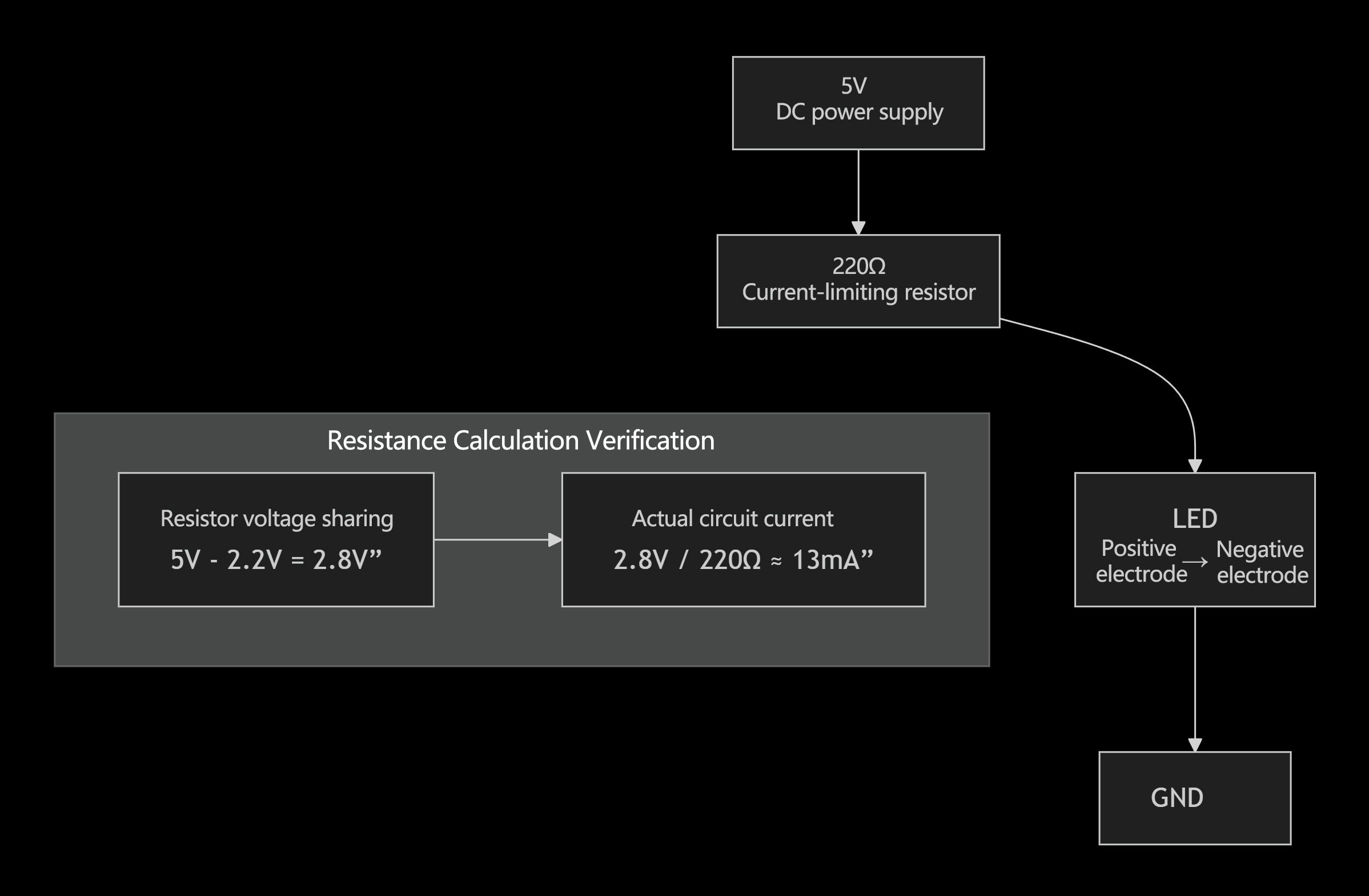
Connection Instructions and Key Points:
Current Path: Current flows out from the positive terminal (5V) of the power supply, first passes through the 220Ω current-limiting resistor, then flows through the LED, and finally returns to the power supply ground (GND), forming a complete circuit.
LED Polarity: LEDs are diodes with polarity and must be connected correctly.
Anode (Positive Terminal, +): The longer lead should be connected to the resistor (i.e., the circuit's high-potential side).
Cathode (Negative Terminal, -): The shorter lead, or the larger electrode inside the LED body, should be connected to GND.
Resistor Non-Polarity: Resistors have no positive or negative terminals and can be connected in either direction
● Arduino and Microcontroller Projects
The 220-ohm resistor serves as an indispensable "guardian angel" in Arduino and microcontroller projects. Its primary applications mirror those in standard circuits, but it places greater emphasis on protecting the expensive and delicate pins of microcontroller chips.
Core Function: Protecting Microcontroller I/O Pins
The input/output (I/O) pins of a microcontroller are incredibly fragile. They can only handle limited current (typically a maximum of 20-25mA per pin, with an overall current limit for the entire chip). Directly connecting a device requiring high current (such as an LED or buzzer) or accidentally causing a short circuit can easily cause permanent damage to the pins or even the entire chip.
The core function of the 220-ohm resistor here is to limit current and provide protection.
Primary Application Scenarios (with Arduino Examples)
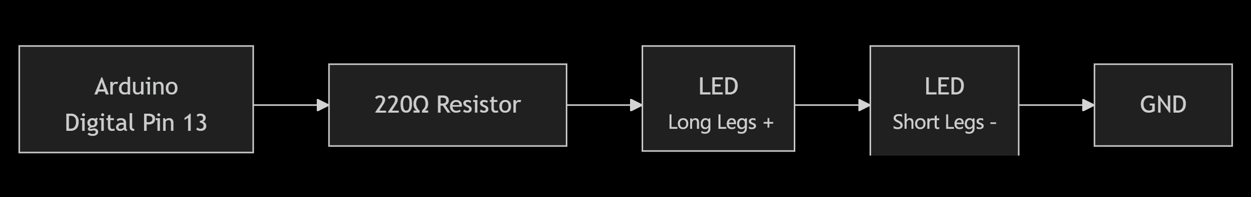
LED Current Limiting (The Most Classic Application): A 220Ω resistor is the standard component used to connect the LED to the Arduino digital pin.
Why 220Ω?
We calculate using Arduino's 5V operating voltage and a typical LED:
Supply voltage (V_s): 5V (from Arduino's 5V pin or digital output high level)
LED forward voltage drop (V_f): ~2.2V
Target current (I): ~20mA (sufficient to drive a standard LED brightly, and well below the Arduino pin's 40mA absolute maximum)
Required resistor R = (V_s - V_f) / I = (5 - 2.2) / 0.02 = 140Ω
Select the most common standard value of 220Ω, which also provides a safety margin.
Actual current I = (5 - 2.2) / 220 ≈ 12.7mA —— This is a very safe current for both the Arduino pin and the LED.
Circuit Connection Diagram (as shown below):
● Voltage division, current limiting, and signal protection applications
A 220-ohm resistor plays multiple critical roles in electronic circuits. In voltage-dividing applications, it is connected in series with another resistor to derive a precise lower voltage from a higher input voltage, such as providing an appropriate bias voltage for sensors or operational amplifiers. Its most classic function is in current limiting, typically when connected in series with LEDs. By dissipating excess voltage through Ohm's Law, it safely restricts the current flowing through the LED to around ten milliamps, preventing burnout from overcurrent and acting as a reliable circuit guardian. Furthermore, in signal protection, this resistor is connected in series with the digital output pins of precision devices like microcontrollers. It effectively suppresses large transient currents (ringing and overshoot) caused by capacitive loads on the line, smoothing signal edges like a "buffer." This safeguards fragile I/O ports from electrical stress damage, ensuring stable communication.
● What does a 220 ohm resistor do?
The 220-ohm resistor stands as one of the most fundamental and versatile components in electronic circuits. Its core function lies in precisely and effectively controlling current flow to shape circuit behavior and ensure safety. Its value is most evident in three key applications.
First, in voltage divider circuits, it is connected in series with other resistors to "divide" a precise lower voltage from a higher supply voltage. This provides suitable bias voltages for components such as sensors, transistors, or operational amplifiers, serving as the cornerstone for building analog circuits and reference voltage points.
Secondly, and most notably, it provides current limiting protection. When driving light-emitting diodes (LEDs), it serves as an indispensable "guardian." LEDs require a constant current rather than voltage. Connecting an LED directly to a power source would cause it to burn out due to a sudden drop in its internal resistance. The 220-ohm resistor dissipates excess electrical energy through itself, limiting the current to a safe range (such as approximately 13mA in a 5V circuit). This not only illuminates the LED but also ensures its long-term reliability.
Finally, in terms of signal conditioning and protection, it also serves as the "safety valve" for digital circuits. When connected in series with the I/O pins of a microcontroller (such as Arduino), it suppresses transient spike currents and signal ringing caused by long wiring or capacitive loads. This prevents irreversible damage to the delicate and fragile chip pins from electrical noise or accidental short circuits.
Choosing the Right 220 Ohm Resistor
Selecting the appropriate 220-ohm resistor hinges on evaluating its power dissipation within the circuit and the required precision of its resistance value.
● Consider parameters: Power (1/4W, 1/2W, 1W), Accuracy (±1%, ±5%)
1. Power Selection: Ensure the resistor does not overheat and burn out.
The power rating of a resistor is the maximum power it can safely dissipate. When selecting a resistor, its actual power consumption in the circuit must be calculated as P = I² × R or P = V² / R, with sufficient margin provided.
◆ 1/4W (0.25W):The most versatile and common choice. Suitable for most low-power scenarios, such as:
○ LED current limiting (typically < 20mA, power consumption well below 0.25W).
○ Pull-up / pull-down resistors in digital circuits.
○ Voltage divider in the signal level.
○Verification: When used in a 5V circuit, P = 5² / 220 ≈ 0.11W, which is well below 0.25W and safe.
◆ 1/2W (0.5W) or 1W:For higher-power applications. When calculating power consumption approaches or exceeds 0.25W, an upgrade is required.
○ Application scenarios: Driving multiple LEDs, serving as a load for small motors, or operating at higher voltages (such as 12V/24V).
○ Verification: If the resistor bears the entire voltage drop in a 12V circuit, P = 12² / 220 ≈ 0.65W. In this case, a resistor rated at 1W or higher must be selected.
○ Rule of thumb: Typically select a rated power that is at least twice the actual calculated power consumption to ensure long-term reliability.
2. Precision Selection: Balancing Circuit Performance and Cost
Accuracy (tolerance) determines the permissible deviation range between the actual resistance value and the nominal value of 220Ω
◆ ±5%:Standard selection, cost-effective. Suitable for "macro" functional circuits where precise resistance values are not critical.
○ Application scenarios: LED current limiting (where slight brightness variation is acceptable), pull-up/pull-down resistors (as long as high/low levels are clearly defined), power-on indicators, relay drivers, etc.
○ Actual range: A 220Ω resistor with a tolerance of ±5%, where actual resistance values between 209Ω and 231Ω are considered acceptable.
◆ ±1%:Precision selection, slightly higher cost. Used in "precision" analog circuits or measurement circuits where resistance values are critical.
○ Application Scenarios: Precision voltage dividers, current sensing resistors, operational amplifier gain settings, sensor interface circuits, etc. The performance of these circuits directly depends on precise resistance ratios or voltage values.
○ Actual range: A 220Ω resistor with a tolerance of ±1%, meaning its actual resistance must fall between 217.8Ω and 222.2Ω.
● Environmental and Temperature Coefficients
Selecting the appropriate 220-ohm resistor based on environmental and temperature coefficients is crucial for ensuring stable and reliable circuit operation under complex conditions. This primarily concerns the resistor's long-term stability and the degree to which its resistance value changes with temperature.
1. Environmental Factors: Determining the Type and Packaging of Resistors
Different environmental conditions impose varying requirements on the material composition and physical protection of resistors.
◆ Ordinary/benign environments (e.g., indoor electronic devices, development boards):
○ Choice: Standard carbon film resistors or thick film chip resistors are sufficient. They are low-cost and meet the requirements of most consumer electronics.
◆ High-temperature/high-humidity/harsh environments (such as automotive engine compartments, industrial motor drives, outdoor equipment):
○ Select: Metal film resistors or metal oxide film resistors are the better choice. They offer superior high-temperature resistance and stability. Additionally, choose resistors with moisture-proof coatings, silicone resin coatings, or even sealed packages to withstand moisture and corrosive gases.
◆ Extreme mechanical stress environments (such as those with intense vibration):
○ Selection: Avoid using axial resistors with long leads, as they may break due to vibration. Surface-mount resistors, being directly soldered onto the PCB, offer superior vibration resistance.
2. Temperature coefficient: Determines the precision stability of the resistor.
The temperature coefficient indicates the degree to which resistance values change with temperature, measured in parts per million per degree Celsius (ppm/°C).
◆ For circuits with low precision requirements (e.g., LED current limiting, pull-up/pull-down resistors):
○ Selection: No special attention to temperature coefficient is required. Standard carbon film resistors may exhibit temperature coefficients as high as ±(500–800) ppm/°C, yet this is entirely acceptable for these applications. For instance, a 50°C temperature change may cause resistance variation of ±(2.5%–4%), which has a negligible impact on LED brightness or digital levels.
◆ For precision circuits requiring high accuracy (such as precision voltage dividers, current sensing, measuring bridges, and amplifier gain networks):
○ Selection: Resistors with low temperature coefficients must be chosen. Metal film resistors with a tolerance of ±100 ppm/°C or ±50 ppm/°C are common choices. For extremely demanding applications, precision thin-film resistors or metal foil resistors with ±25 ppm/°C, ±15 ppm/°C, or even ±5 ppm/°C may be selected.
○ Calculation example: For a 220Ω resistor with a temperature coefficient of ±100 ppm/°C, the maximum resistance change when the temperature rises by 25°C is ΔR = 220Ω × 100 × 10⁻⁶ × 25 = 0.55Ω. This minute variation is acceptable in precision circuits.
● unikeyic 220Ω Resistor Recommended
1. Vishay RLR07C2200GRB14 220Ω Metal Film 0.25W ±2% Metal film, high precision (±2%), 0.25W power rating, suitable for precision signal or analog circuits.
2. Vishay CPF2220R00FKE14 220Ω 2W Metal Film ±1% High power rating up to 2W with high accuracy (±1%), suitable for power circuits or high-heat environments
3. YAGEO MFR-25FTE52-220R Metal Film Resistor 220 Ω ±1% 0.25W YAGEO MFR-25FTE52-220R is a high-stability metal film precision resistor with a nominal resistance of 220 Ω, tolerance of ±1%, and rated power of 0.25 W (¼ W). This series is renowned for its excellent temperature stability and low noise characteristics, making it widely used in signal processing, power supply circuits, and measurement and control systems.
Summary
● Key Points Review (Color Wheel, Reading, Application)
1. Color Ring: The "Colorful ID Card" for Identity Recognition
Color bands serve as a visual code for quickly identifying 220-ohm resistors, primarily consisting of two types:
Four-color band (standard accuracy, ±5%): Red - Red - Brown - Gold
Red (2) - Red (2) - Brown (×10) - Gold (±5%)
Calculation: 22 × 10 = 220Ω
Five-band code (high precision, ±1%): Red - Red - Black - Black - Brown
Red(2) - Red(2) - Black(0) - Black(×1) - Brown(±1%)
Calculation: 220 × 1 = 220Ω
Ke Point: This represents the resistor's "nominal value," but the actual resistance falls within a tolerance range.
2. Read: "Verification step" to confirm identity
Correct reading involves interpreting color bands and final verification:
Direction determination: Locate the tolerance band (gold or silver), which is always on the far right. Begin reading from the opposite side of this band.
Final verification: Must be measured using a multimeter. Disconnect at least one end of the resistor from the circuit and measure using the resistance setting.
Normal: The reading should fall within the tolerance range (e.g., for a ±5% resistor, a reading between 209Ω and 231Ω is normal).
Damaged: The reading is either infinite (open circuit) or close to zero ohms (short circuit).
Key Point: Color bands provide the nominal value; the multimeter verifies the actual value and determines functionality.
3. Application: The "Core Stage" Where It Takes Center Stage
The 220-ohm resistor plays a crucial role in three key scenarios through current limiting and voltage division:
LED Current Limiting Protection (The Most Classic):Connected in series between the LED and the power source (such as the 5V pin on an Arduino), it safely limits the current to ~13mA by absorbing excess voltage, preventing the LED and driver chip from burning out due to overcurrent. It serves as the circuit's guardian.
voltage divider:When connected in series with other resistors, it divides a precise lower voltage from a high voltage source, providing an appropriate operating point for devices such as sensors and amplifiers.
Signal Protection and Conditioning:Connected in series between the microcontroller's I/O pins and external components, it suppresses transient spike currents and ringing on signal lines, protecting delicate pins from electrical stress damage. It acts as a "buffer" for the signal.
Key Point: Its core value lies in precisely controlling current and voltage to achieve functionality, ensure stability, and guarantee safety.