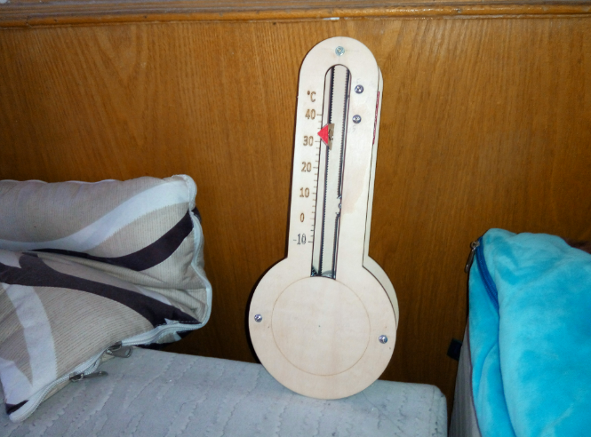
A mechanical transmission structure thermometer that will surpass your imagination
I happened to notice the thermometer at home. This kind of thermometer aligns with my traditional understanding of what a thermometer should look like. However, modern manufacturers seem to lack creativity in their designs. They simply slap an LED screen onto a basic, square-shaped device, which looks quite dull and doesn't blend well with the home environment. Therefore, I thought about utilizing the classic appearance of a traditional thermometer, integrating some mechanical structures to display the temperature. By using synchronous belt gears to convey temperature changes, it could become a highlight within the household.

Structure:
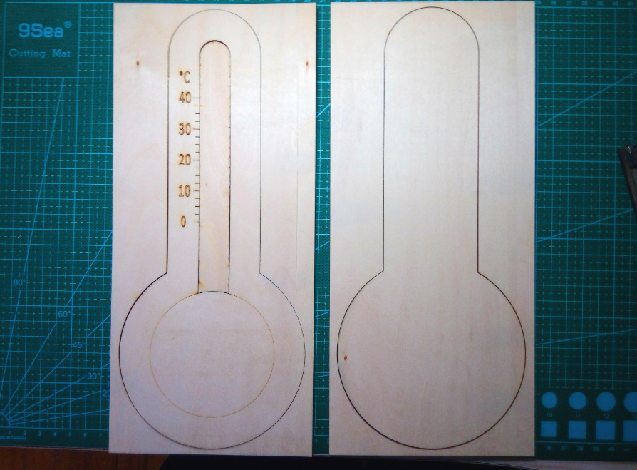
First, it comes down to choosing materials. I was previously torn between acrylic and basswood panels, uncertain as to which would be more suitable. However, after observing the décor in several homes, I noticed that wood finishes were predominantly favored. Hence, I have come to the conclusion that using basswood layers would be a better choice.
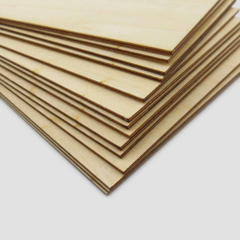
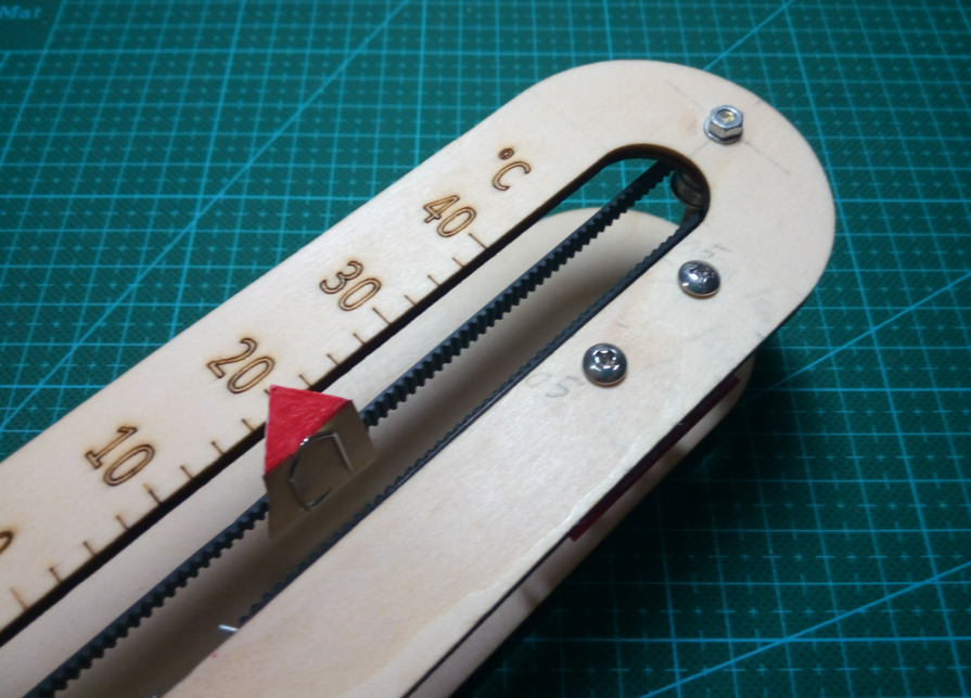
In line with a more contemporary style, the wooden panels are also easier to process, facilitating subsequent procedures. For temperature display, I plan to use a mechanism similar to that of a 3D printer: employing a stepper motor to drive a timing belt, which in turn moves the pointer across the dial. This approach ensures the stability of the pointer and the accuracy of temperature indication. I had also considered using a lead screw and slide table for the drive mechanism, but ultimately abandoned this idea due to the high cost associated with lead screws and slide tables.
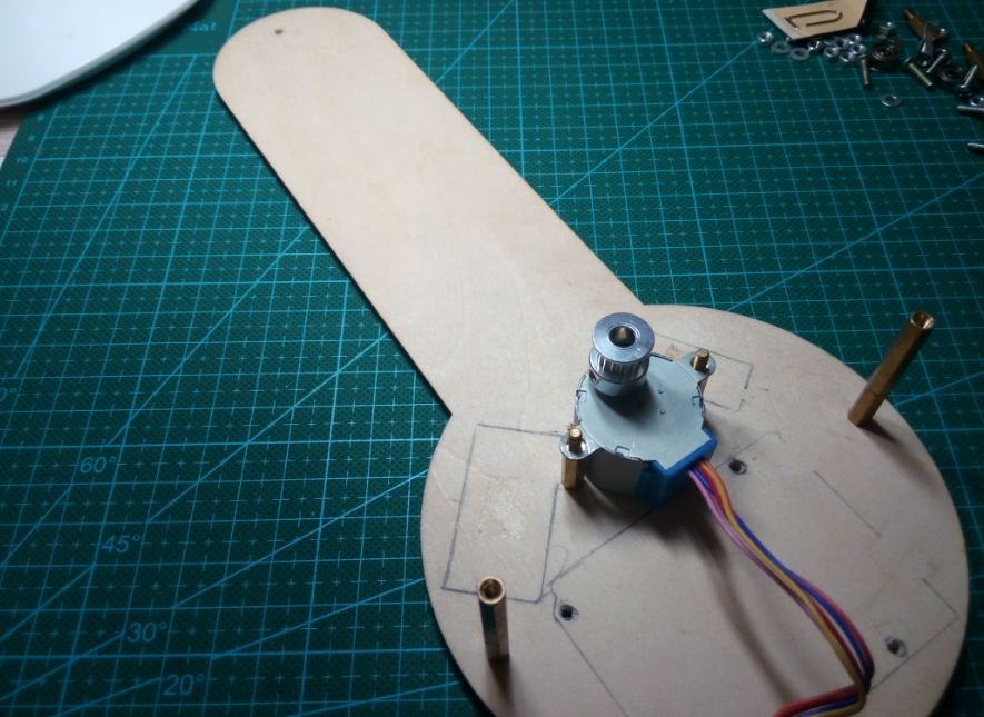
Next comes the selection of motors and drive components. The widely available 42 stepper motor is commonly used in various robots and 3D printers, known for its exceptional stability. However, its drawback lies in its excessive size, making it unsuitable for use in thermometers. After careful consideration, the 28BYJ48 geared stepper motor was ultimately chosen.
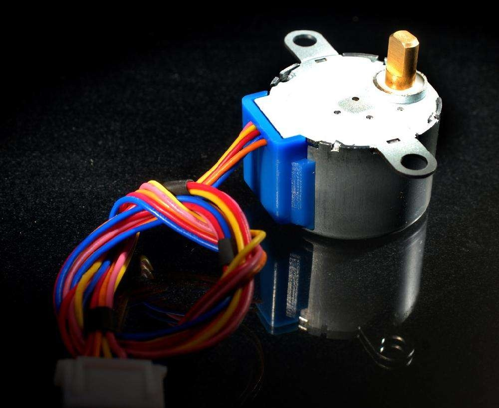
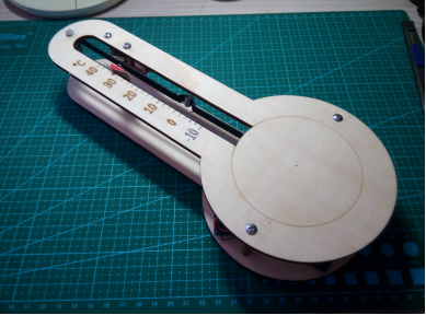
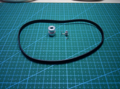
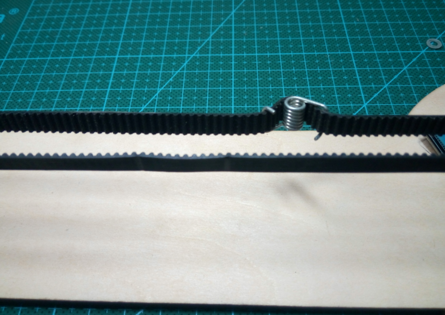
This stepper motor is compact in size and operates at low current, which can be driven by the ULN2003 chip. It is also more affordable than the NEMA 17 stepper motor and comes with a reduction gear, ensuring adequate torque. The output shaft is a 5mm D-shaped shaft that is compatible with commonly available synchronous pulleys on the market. For the transmission system, standard components frequently used in 3D printers can be employed. I used a 16-tooth GT2 synchronous pulley as the driving wheel to drive the timing belt, while the driven wheel setup is quite simple, requiring only two bearings. This approach is both straightforward and cost-effective, eliminating the need to purchase idler pulleys. The tension of the timing belt determines the accuracy of the pointer's indication, so I added a tension spring to ensure the timing belt remains taut at all times.
There are various methods for creating a pointer. I used a paperclip to indicate the temperature; the paperclip can be firmly attached to the timing belt, making it stable and resistant to movement.
Circuit:
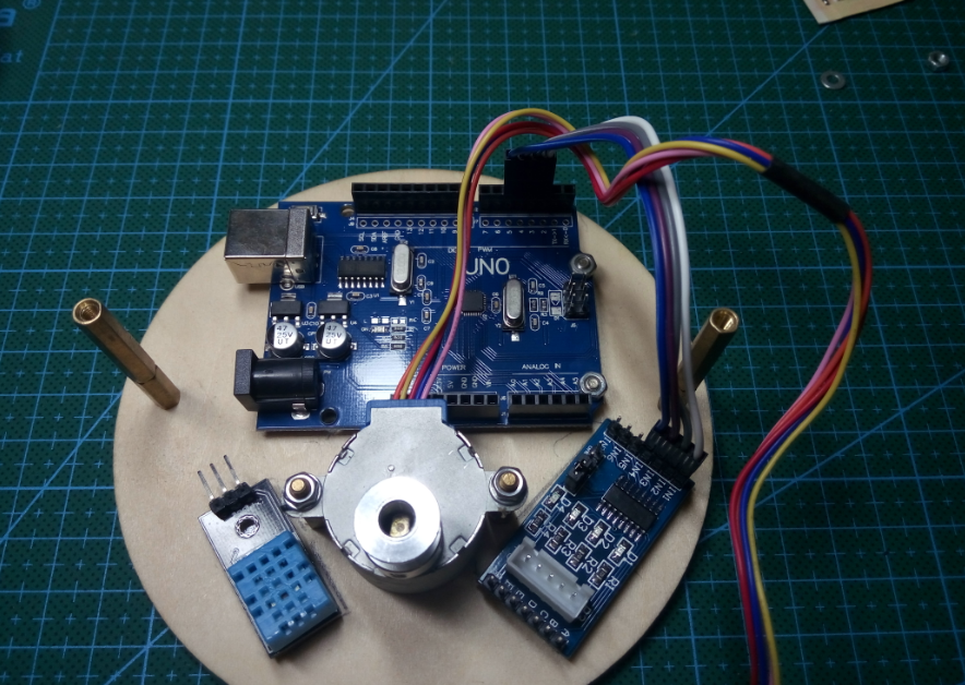
For the microcontroller, I opted for the Arduino Uno.
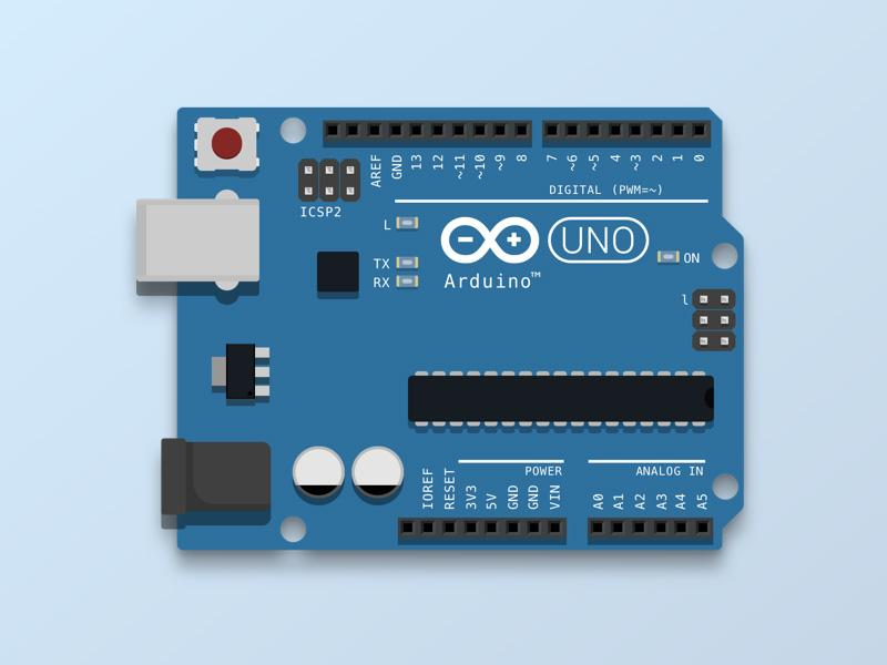
The Arduino Uno supports numerous open-source libraries and sensors, making it exceptionally easy and user-friendly for programming. Unlike other microcontrollers that require an understanding of various complex registers, the Arduino Uno can achieve many functionalities with simple commands. In terms of performance, the Atmega328 microcontroller embedded in the Arduino Uno offers sufficient resources, and its RISC architecture enhances its capabilities, making the Arduino Uno more than adequate for this project.
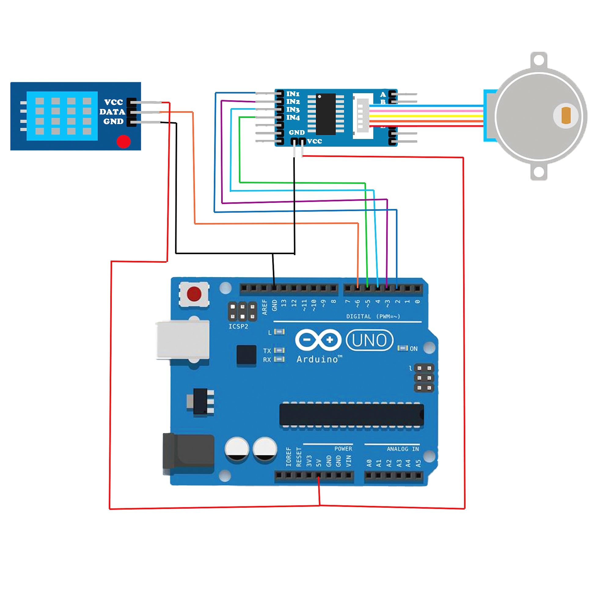
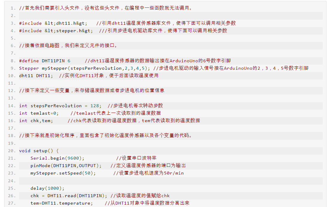
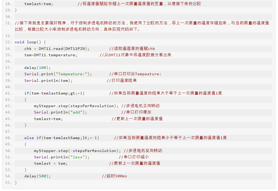
Once the microcontroller is selected, choosing other components becomes much simpler. For temperature measurement, the DHT11 temperature and humidity sensor is used; it can measure environmental temperature and humidity. The single-wire data transmission method saves port resources, and thanks to Arduino's open-source environment, using this sensor is exceedingly straightforward—just one function call retrieves temperature and humidity information, making it the ideal choice for creating a thermometer.
For driving the stepper motor, the ULN2003 high-power Darlington transistor array module is employed. This module is easily accessible and inexpensive, making it the perfect match for the chosen stepper motor. The onboard 4-channel LED indicators provide a clear view of each phase's operational status.

We would like to extend our gratitude once again to the open-source environment provided by Arduino. Thanks to the contributions of numerous experts, the function library for this driver module has already been written for us, and we merely need to call upon it. Here is the meticulously designed circuit diagram:
After completing the structural design and components, the next step is to design the blueprints for the wooden boards. After a short while of busy work, the blueprints are finalized and sent to the manufacturer for cutting. A few days later, the cut wooden boards are received.
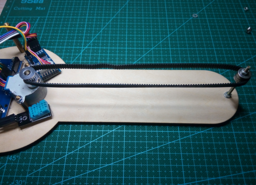
Next comes the installation. Carefully place each component in its designated position and properly connect the wiring.
Program:
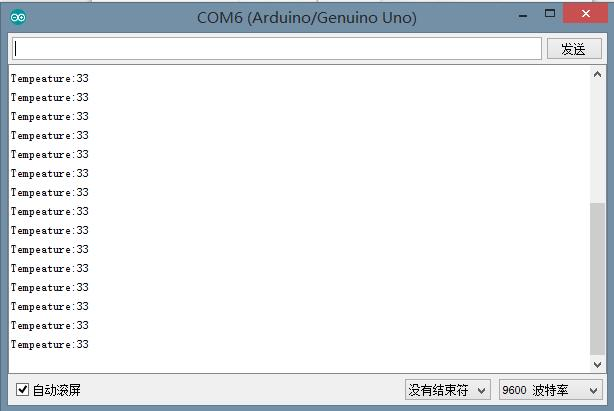
Connect the computer, upload the code to the Arduino Uno, open the serial monitor, and observe the temperature values displayed on the screen.
Adjust the position of the paperclip pointer and the tension spring. Once these adjustments are made, a thermometer that is both technologically advanced and artistically crafted will be complete.