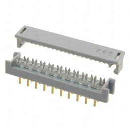
Types of Connectors on a Motherboard: The Ultimate Identification Guide
Overview: What are the common types of connectors found on a motherboard?
Modern motherboards integrate power, storage, cooling, lighting, and front I/O headers in a compact layout. Understanding what each connector does---and how to identify it correctly---helps reduce assembly errors, compatibility issues, and troubleshooting time. s Think of the motherboard as the system's "wiring hub," where interfaces for power, storage, peripherals, and fans handle tasks such as power delivery, data transmission, and control signals. Identifying connectors by functional zone is far more efficient than cross-referencing each one against a manual.
Common connectors are divided into three main categories: power connectors, data/storage connectors, and peripheral and control connectors, making it easier for you to quickly locate them on the actual board.
1. Power Connector Area: The Motherboard's Power Source
Located on the upper-left and right edges of the motherboard layout, this area is where the key PCB components responsible for power delivery are concentrated.
- Main Power Connector (24-pin ATX): Typically, the largest connector on the motherboard, it distributes power from the PSU to various circuits on the board.
- CPU Power Connector (4+4-pin or 8-pin): Usually located near the CPU socket, this connector provides a dedicated, stable power supply to the processor.
- GPU Auxiliary Power (PCIe Power): GPU auxiliary power is typically supplied through 6-pin or 8-pin PCIe power connectors, and some high-power graphics cards use multiple connectors (such as 8-pin + 8-pin or 8-pin + 6-pin). s
2. Data and Storage Connectors: The Carriers of Information
Storage-related interfaces, such as SATA ports and M.2 slots, are typically concentrated on the right and lower-right sides of the motherboard to facilitate cable management for hard drives and allow for adequate cooling space.
- SATA Interfaces: SATA is one of the most common wired storage interfaces today, used to connect 2.5-inch SATA SSDs, 3.5-inch mechanical hard drives, and SATA optical drives still in use. SATA Revision 3.x provides a 6 Gbps link rate, with real-world sequential transfer speeds for SATA SSDs typically lower due to protocol overhead; actual sequential read/write speeds typically range in the hundreds of MB/s.
- M.2 Slots: M.2 slots are among the most critical high-speed storage interfaces on recent motherboards, allowing for the direct installation of PCIe NVMe SSDs or certain M.2 Wi-Fi/Bluetooth modules.NVMe SSDs transmit data via PCIe x4 lanes. On PCIe 3.0/4.0 platforms, sequential read/write speeds commonly reach several GB/s. Compared to SATA interfaces, they are faster and eliminate the need for data and power cables, resulting in a cleaner interior and improved airflow within the chassis.
3. Peripheral and Control Connectors: The Bridge for Human-Computer Interaction
Located at the bottom edge of the motherboard layout and on the rear I/O panel, these connectors primarily handle communication with external devices.
- Front Panel Connector (F-Panel): This is a row of densely packed small pins used to connect the wiring harnesses for the chassis front panel's power button, reset button, power indicator, and hard drive indicator. You must connect the positive and negative terminals correctly according to the labels on the motherboard (such as PWR_SW, RESET, PLED, and HDD_LED) for the motherboard to power on properly when the power button is pressed.
- USB and audio interfaces are divided into two parts: first, the USB/HD_AUDIO header pins on the edge of the motherboard, used to connect to the USB-A, USB-C, and headphone/microphone jacks on the front panel; second, the integrated ports on the I/O shield, used to directly connect keyboards, mice, USB drives, or speakers. When connecting the front panel cable harness, pay close attention to the shape and notch positions of the USB 2.0, USB 3.x, and USB-C pins to avoid accidentally inserting USB pins into the fan or COM ports.
- Fan headers (CHA_FAN, SYS_FAN, etc.): These are typically 3-pin or 4-pin mini-connectors distributed across various areas of the motherboard, used to power case fans and collect RPM signals.4-pin connectors support PWM speed control, while 3-pin connectors typically use voltage control; prioritize connecting case fans to the motherboard's fan headers rather than directly to the power supply's D-type connectors, as this allows for unified speed control and noise reduction via the BIOS or software.
Understanding the three main categories of connectors on the motherboard---power, data/storage, and peripherals/control---is not just about "recognizing the ports"; it is the first step toward proper cable management, upgrading storage (SATA/M.2), installing fans, and troubleshooting issues like the system failing to boot or displaying a black screen. When encountering problems, simply determining whether the issue involves a power, data, or front-panel connector will make the troubleshooting process much clearer.
Power Connectors: Bringing Life to Your System
The power connectors on the motherboard are responsible for distributing voltage rails such as +3.3 V, +5 V, and +12 V from the power supply unit (PSU) to various components: the 24-pin ATX main power connector provides basic power to the motherboard's logic circuitry and expansion slots; the 8-pin or 4+4-pin EPS12V connector specifically supplies high-current +12 V to the CPU power module; while PCIe auxiliary power connectors, such as the 6+2-pin, deliver additional +12 V directly to the discrete graphics card. Remember this basic rule: "The 24-pin powers the entire board, the EPS powers the CPU, and the PCIe powers the graphics card." This will help you avoid plugging in the power cables incorrectly during assembly. For a more focused breakdown of PSU-side plugs, pin roles, and identification details, see the computer power connector types section.
● 24-Pin ATX Power Connector
The 24-pin ATX connector is the primary power input for most desktop motherboards, distributing DC power from the PSU throughout the board. It typically uses the industry-standard Molex Mini-Fit Jr. connector housing and crimp terminals, which can handle approximately 8- 9 A per pin (depending on wire gauge) and feature latches and keyed alignment to reduce the risk of disconnection due to vibration or incorrect insertion.
Technical Background: The Molex Mini-Fit Jr. Series and the Main Power Supply
In motherboard layouts, the 24-pin ATX connector is generally positioned along the right edge, facilitating power cable routing while avoiding obstruction of the heatsink. It simultaneously carries +3.3 V, +5 V, +12 V, -12 V, +5 VSB, and multiple ground lines, providing power to onboard loads such as the chipset, memory slots, and PCIe slots, and is the critical entry point for the system to boot up and run stably.
20+4-Pin Design: a backward-compatible implementation of the ATX main power connector.
As PC power requirements grew, the ATX specification evolved from the early 20-pin design to 24 pins. This change gave rise to the 20+4-pin split design, whose core purpose is to ensure compatibility between old and new hardware:
- 20-pin era (ATX v1.x): During the early Pentium 3 and early Pentium 4 eras, motherboard power consumption was low, and the 20-pin interface was sufficient to meet demands. However, as power consumption from CPUs and PCIe graphics cards rose, the +12V power supply capacity became insufficient.
- 24-pin era (ATX v2.x): In the transition from ATX v1.x to ATX v2.x, the main power connector expanded from 20 pins to 24 pins. In the 24-pin ATX revision, the extra four positions add current capacity for the main rails and ground, improving power delivery headroom for newer motherboards and expansion slots, providing greater current headroom for each voltage rail---especially the +12 V rail---and making it better suited for powering high-load components such as PCIe slots.
- Compatibility Implementation: The 20+4-pin design splits the 24-pin connector into a 20-pin main connector and a separate 4-pin connector. This design has two primary use cases:
- New power supply with an older motherboard: If you are using a 24-pin power supply but your motherboard only has a 20-pin socket, simply insert the 20-pin main block and leave the 4-pin block unplugged. This allows the new power supply to be backward compatible with older platforms.
- Old power supply with a new motherboard: If the power supply only has a 20-pin connector but the motherboard requires a 24-pin one, you can connect them physically using a 20-to-24-pin adapter cable. However, older power supplies of this type are typically designed for older platforms, with lower +12V output capacity and reduced overall power reserves. When used on new platforms with discrete graphics cards or high-power CPUs, they are more prone to voltage drops, screen flickering, or reboots under heavy loads. In practice, it is recommended to select a new power supply with native 24-pin connectors and one with a rated power and +12V current that meet the system's requirements.
It is important to note that while physically compatible, the power delivery capabilities are not entirely equivalent. When using a 20-pin power supply with a 24-pin motherboard, the absence of the additional +12V lines may reduce power delivery to the PCIe slots, which in turn can compromise graphics card stability.
Practical Application and Identification
Today, nearly all desktop motherboards use a 24-pin main power connector, and the Molex Mini-Fit Jr. series connectors are widely adopted for their reliability. During assembly, you can easily identify them by their large form factor (typically about 3.8 cm long and 1.5 cm wide) and their latch design. The latch ensures the connector locks securely into the socket, preventing loosening due to vibration or shipping.

● 8-Pin/4-Pin EPS12V CPU Power Connector
The 8-pin or 4+4-pin EPS12V connector is specifically designed to power the CPU VRM and is a critical component for system stability. It resembles the PCIe 8-pin connector in appearance but has a different pinout, and the cable is usually marked with "CPU" or "EPS"; those for graphics cards are labeled "PCIe" or "VGA."When assembling a system, be sure to check the labels and connect the cables to the correct ports to avoid accidentally plugging the CPU power cable into the graphics card---or vice versa---which could prevent the system from booting or even damage the hardware.
What is the EPS CPU power connector?
The EPS (Entry-Level Power Specification) standard was originally designed for servers and workstations, but has since been widely adopted by consumer-grade motherboards. CPU power connectors typically feature 4-pin, 8-pin, or even dual 8-pin designs, connecting directly to the power supply unit (PSU) to deliver power to the CPU. It relies on the +12V voltage rail, which is converted into low-voltage core voltages via motherboard PCB components (such as MOSFETs and capacitors) to ensure stable processor operation.
- 4-pin ATX12V: Introduced during the early Pentium 4 era, it provides additional +12V current to supplement the 24-pin main power connector.
- 8-pin EPS12V: As the power consumption of multi-core CPUs increased, the 8-pin connector became the mainstream standard. It is essentially a combination of two 4-pin connectors and can be split to accommodate older motherboards.
- Dual 8-pin/8+4-pin: Used in high-end enthusiast platforms (such as Intel LGA1700/2066 or AMD Threadripper) to meet the demands of extreme overclocking or a surge in the number of cores.
These connectors are collectively referred to as CPU power connectors, and their physical form typically utilizes Molex Mini-Fit Jr. series connectors to ensure high current-carrying capacity and a secure latch.
EPS vs. PCIe 8-pin: A World of Difference in Design
One of the most common mistakes made by novice PC builders is forcing a PCIe graphics card power cable into a CPU power connector. Although both have a similar appearance---both being 8-pin---their pin definitions and anti-misinsertion mechanisms are completely different. Forcing them into the wrong sockets can cause short circuits or even burn out hardware.
| Features | EPS 12V 8-pin (CPU) | PCIe 6+2-pin (Graphics Card) |
|---|---|---|
| Latch Position | The latch is located on the longer side (the side of the connector is rectangular) | The latch is located on the shorter side (the side of the connector is trapezoidal) |
| Pin Shape | Mostly square pins, with some rounded square pins | Mostly a rounded square, with mixed designs |
| Pin Assignment | 4 x +12V, 4 x GND | 3 x +12V, 5 x GND (6+2-pin PCIe) |
| Compatibility | Exclusively for CPU sockets | Dedicated to GPU auxiliary power |
Key Difference: The latch on the EPS connector is located on the side without the beveled edge (i.e., the top of the connector is flat), while the latch on the PCIe connector is located on the side with the beveled edge (i.e., the top of the connector has a trapezoidal notch). This physical anti-misinsertion feature ensures that only the correct connector can be inserted into the corresponding socket. Applying excessive force may damage the motherboard socket or the power cable.
Power Connectors vs. Fan Connectors: Another Lesson in Preventing Misinsertion
In addition to power connectors, motherboard layouts feature numerous small connectors, such as fan headers. This leads to a common PAA question: Different Motherboard Fan Headers? Fan headers (such as CPU_FAN and SYS_FAN) are typically 4-pin PWM or 3-pin DC connectors used to connect cooling fans, and they differ significantly from CPU power connectors:
- Size: Fan headers are 4-pin headers (2.54mm pitch), while the CPU power connector is an 8-pin square socket (4.2mm pitch).
- Voltage: Fan headers output 5V or 12V (via PWM or DC speed control), whereas the CPU power connector is specifically designed to deliver high-current +12V.
- Misinsertion prevention: Although the fan connector lacks latches, it typically features anti-misinsertion protrusions, whereas the CPU power connector has distinct latches.
Understanding these differences can prevent accidentally plugging a fan into the power supply socket (which is impossible due to the mismatched dimensions), but more importantly, it ensures you do not mistakenly plug a graphics card PCIe cable into the CPU power socket.
The Role of EPS Connectors in Entry-Level Power Supply Systems
The EPS 12V standard has now become an integral part of entry-level power supply systems. Even in entry-level configurations, CPU power consumption generally exceeds 65W, making the 8-pin EPS connector a standard feature on nearly all desktop motherboards. For budget-conscious builds, ensuring the power supply provides a 4+4-pin EPS connector is sufficient to support the vast majority of mainstream platforms.
Storage Interfaces: Connecting HDDs and SSDs
In the computer hardware ecosystem, storage interfaces serve as the data bridge between the motherboard and hard disk drives (HDDs) and solid-state drives (SSDs). Whether it's a high-capacity mechanical hard drive used for backing up photos and videos or an NVMe solid-state drive designed for ultimate responsiveness, both must connect to the motherboard's PCB components via specific interfaces to enable data read/write operations. The choice of storage interface directly impacts system performance and the data access experience.SATA interfaces reliably meet high-capacity storage needs with their proven stability, while M.2 interfaces continually push the boundaries of data transfer rates to satisfy the exacting demands of professional creators and gamers.
SATA Interface: The Cornerstone of High-Capacity Storage
The SATA (Serial ATA) interface is the backbone for connecting high-capacity storage devices. Since its inception in 2003, it has become the standard interface for mechanical hard drives and 2.5-inch SATA SSDs thanks to its excellent compatibility and cost-effectiveness. On motherboard layouts, SATA ports are typically located in the lower-right corner, arranged in an L-shape.
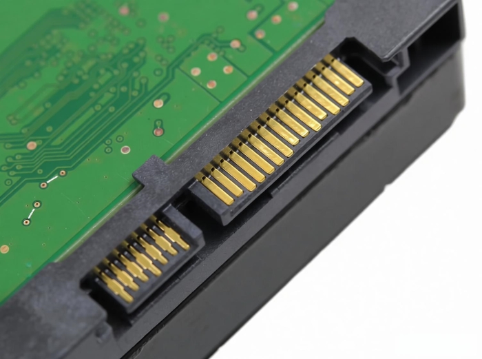
- Physical Features: A 7-pin data connector paired with a 15-pin power connector, supporting hot-swapping.
- Data Transfer Rate: SATA 3.0 has a theoretical bandwidth of 6 Gbps, with an actual effective data transfer rate of approximately 560 MB/s. While this is more than sufficient for mechanical hard drives (which reach speeds of up to about 200 MB/s), it has become a bottleneck for modern SSDs.
- Use Cases: Ideal for building high-capacity storage repositories (such as multi-bay NAS systems or cold backup solutions), enabling the creation of storage spaces ranging from several terabytes to tens of terabytes at a low cost.
M.2 Interface: Pushing the Limits of Data Transfer Rates
The M.2 interface (formerly known as NGFF) is currently the mainstream choice for solid-state drives. It is directly integrated onto the motherboard PCB and features a compact form factor. It supports both SATA and PCIe interfaces, with PCIe 4.0 and PCIe 5.0 NVMe SSDs that can deliver sequential transfer rates above 7,000 MB/s and 10,000 MB/s, respectively, depending on controller, NAND, and platform support.
- Physical Features: Slots are categorized as B-key and M-key; typically, the M-key (supporting PCIe x4) is used for high-speed NVMe SSDs.
- Performance Leap: High data transfer rates significantly reduce response times in scenarios such as game loading, video editing, and big data analysis.
- A New Option for High-Capacity Storage: M.2 SSD capacities have expanded from the early 128GB to 4TB or even 8TB, gradually meeting some high-capacity storage needs, making them particularly suitable for compact systems that prioritize both size and speed.
Other Storage Interfaces and Expansions
- U.2 Interface: Primarily used in enterprise-level data centers, it supports the NVMe protocol and balances high-capacity storage with high data transfer rates. However, it is bulky and requires a dedicated cable for connection.
- mSATA Interface: Has largely been replaced by M.2 and is commonly found in older devices.
● SATA Data Connectors (SATA III)
Detailed Explanation of SATA Data Connectors: L-shaped polarized design ensures a secure connection
The SATA data interface is the standard connector for connecting motherboards to 2.5-inch and 3.5-inch hard drives (including both mechanical and solid-state drives). Its physical design features a unique L-shaped connector, with one side cut at a right angle to achieve a one-to-one alignment with the plug. This anti-misinsertion design ensures users can insert the drive only in the correct orientation, effectively preventing pin damage from forceful installation. The standard SATA data interface features a 7-pin configuration, comprising three ground lines and four differential signal lines, supporting a maximum data transfer rate of 6Gbps (SATA 3.0). This L-shaped design not only enhances installation reliability but also ensures stable operation of high-capacity storage devices, and it remains an indispensable connection method in mainstream storage solutions to this day.
Before connecting any motherboard header, verify three things first: the connector type, the keying direction, and the rated voltage. Many installation mistakes happen not because the header is hard to find, but because two similar-looking connectors are assumed to be interchangeable.
● M.2 Slots (NVMe & SATA)
What is an M.2 slot?
M.2 (formerly known as NGFF) is an expansion interface directly integrated onto the motherboard PCB, suitable for devices such as solid-state drives and wireless network cards. As a next-generation form factor, it eliminates the cable constraints of SATA interfaces and supports both PCIe and SATA transfer protocols. PCIe 4.0/5.0 NVMe SSDs can achieve data transfer rates exceeding 10,000 MB/s, significantly improving system response times.
M.2 slots are categorized into different keys based on the position of the notch (anti-misinsertion feature), with the most common being the B key and the M key. These keys determine the SSD's physical compatibility and electrical protocol; inserting the SSD incorrectly may result in it not being recognized or even damaging the interface.
Key M vs. Key B: Key Differences Comparison Table
Below is a detailed comparison of Key M and Key B, including notch position, supported protocols, maximum bandwidth, and recommended use cases:
| Comparison Item | B Key | M Key (M key) |
|---|---|---|
| Notch Location | Notch located on the right side of the slot (between pins 12 and 19) | The notch is located on the left side of the slot (between pins 59 and 66) |
| Supported protocols | SATA or PCIe x2 (optional) | PCIe x4 (required) or SATA (optional) |
| Maximum Bandwidth | PCIe 3.0 x2: approx. 16 Gbps; SATA: 6 Gbps | PCIe 4.0 x4 approx. 64 Gbps; PCIe 5.0 x4 approx. 128 Gbps |
| Common SSD Types | Older or entry-level SATA M.2 SSDs; some wireless network cards | Mainstream high-performance NVMe M.2 SSDs |
| Physical compatibility | Can be inserted into B&M slots; cannot be inserted into pure M-key slots | Can be inserted into B&M slots; cannot be inserted into pure B-key slots |
| Typical Applications | Upgrading older laptops; budget-friendly builds | Gaming PCs, workstations, and content creation platforms |
As shown in the table, the M-key is primarily designed for high-performance PCIe x4 lanes, while the B-key is typically limited to SATA or PCIe x2. Many M.2 SSDs feature a B&M-key design (i.e., with two notches), making them compatible with both types of slots; however, in such cases, performance may be limited by the slower lane.
How to distinguish and choose?
When purchasing an M.2 SSD or checking motherboard specifications, you can quickly identify the type using the following methods:
- Check the notch: If the SSD's gold contacts have only one notch on the left side, it is an M-key (M key) and is compatible with PCIe x4 slots. If the notch is on the right side, it is a B-key (B key).
- Check the motherboard labeling: Next to the M.2 slot on the motherboard layout, you'll typically see "M key" or "B key" printed, along with the supported protocol (e.g., "PCIe 4.0 x4").
- Consider the interface: If you're looking for maximum speed, choose an NVMe SSD with an M-key; if you're using it solely for storage (large-capacity storage) and your motherboard only supports SATA M.2, a SATA SSD with a B-key or B&M-key will suffice.
Cooling and Thermal Management: Fan Headers
In PC hardware, thermal management is a critical factor in ensuring stable system operation. Fan headers on the motherboard are responsible for powering and controlling the speed of case fans, CPU cooler fans, and other components.
Although motherboard fan headers are small, they directly impact the system's overall cooling performance. Understanding the difference between 3-pin and 4-pin connectors is key to grasping the fundamentals of DC speed control and Pulse Width Modulation (PWM).If you prioritize ultra-quiet operation and precise temperature control, opt for 4-pin PWM fans and connect them to 4-pin headers. If you have older 3-pin fans on hand, there's no need to worry — simply set them to DC mode in the BIOS, and they will function normally. Only by properly matching fans with their corresponding headers can you ensure your "cooling system" remains in optimal condition at all times.
On a motherboard, fan headers are typically located around the CPU socket and along the edges. The three most common headers---CPU_FAN, SYS_FAN, and AIO_PUMP---each serve distinct purposes and follow different speed control logic. Understanding these differences is key to building an efficient cooling system.
Key Differences Among the Three Connectors
| Connector Type | Primary Purpose | Default Speed Control Logic | Key Features |
|---|---|---|---|
| CPU_FAN | CPU Cooler Fan | Dynamic speed control (varies with CPU temperature) | BIOS-enforced detection; may prevent boot if not connected |
| SYS_FAN | Chassis Fan (Intake/Exhaust) | Dynamic speed control (based on system or custom temperature profiles) | Multiple units can be connected to optimize overall airflow |
| AIO_PUMP | All-in-One Liquid Cooling Pump | Full-speed operation (default 100% RPM) | Supports high current; frequent speed adjustments may shorten pump lifespan |
3-pin vs. 4-pin: DC speed control vs. Pulse Width Modulation
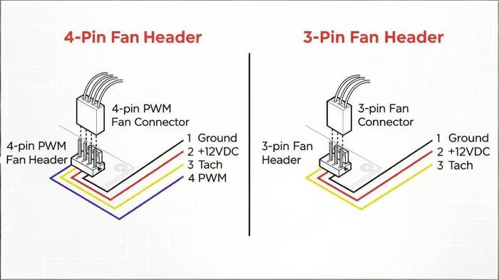
The key distinction between fan connectors lies in the number of pins and the method of speed control. Common 3-pin connectors use DC speed control, while 4-pin connectors support pulse width modulation.
1. 3-Pin Fan Connectors and DC Speed Control
The pin definitions for a 3-pin connector are:
- Pin 1: GND (Ground)
- Pin 2: +12V (Power Supply Positive)
- Pin 3: Speed signal (Tachometer)
When fan speed needs to be adjusted, the motherboard does so by altering the supply voltage on Pin 2 — this is known as DC speed control. For example, reducing the voltage from 12V to 7V will correspondingly lower the fan speed.
Features of DC speed control:
- Simple structure and high compatibility
- Supported by virtually all motherboards
- Limited speed control range (the fan may stop if the voltage is too low)
- May produce motor commutation noise at low voltages
2. 4-Pin Fan Connector and Pulse Width Modulation
The 4-pin connector adds a fourth pin---the PWM control signal---to the 3-pin configuration:
- Pin 1: GND (Ground)
- Pin 2: +12V (constant power supply)
- Pin 3: Speed signal (Tachometer)
- Pin 4: PWM control signal
The working principle of Pulse Width Modulation (PWM speed control) is as follows: While maintaining a constant 12V power supply, a square wave signal is transmitted via Pin 4 to control the on-off time ratio (duty cycle) of the fan's internal drive circuit. For example, a 50% duty cycle means the fan operates at 50% power.
Features of Pulse Width Modulation:
- Wide speed control range (0%--100% linear adjustment)
- Smoother and quieter operation at low speeds
- Rapid response and precise temperature control
- Requires a built-in PWM control chip in the fan
- Slightly higher cost than DC fans
How to identify and connect correctly?
| Scenarios | Procedure |
|---|---|
| Connect a 4-pin fan to a 4-pin connector | Optimal combination; can be set to PWM mode in the BIOS to achieve precise pulse width modulation speed control |
| 3-pin fan plugged into a 4-pin connector | You must set this connector to DC mode (voltage control) in the BIOS; otherwise, the fan may run at full speed |
| 4-pin fan plugged into a 3-pin connector | Can be plugged in, but PWM functionality is disabled; the fan will run at full speed (unless the motherboard supports voltage regulation) |
| 3-pin fan plugged into a 3-pin connector | Standard connection; uses DC speed control mode, with speed regulated via voltage |
Speed control settings in the BIOS
Modern motherboard BIOS/UEFI typically offers the following modes for each fan header:
- PWM mode: Suitable for 4-pin fans; precisely controls speed via a pulse-width modulation signal
- DC Mode: Designed for 3-pin fans; adjusts speed by varying the voltage
- Auto Mode: The motherboard attempts to automatically detect the fan type (it is recommended to manually confirm this to ensure proper operation)
Additionally, advanced motherboards support custom temperature-speed profiles, allowing PWM or DC speed control to dynamically respond to CPU or chassis temperatures, achieving the perfect balance between cooling performance and quiet operation.
● CPU_FAN vs. SYS_FAN vs. AIO_PUMP
In motherboard cooling systems, CPU_FAN, SYS_FAN, and AIO_PUMP are the three most common fan headers. They all appear as pin headers on the motherboard layout, but each serves a different cooling function and supports different fan-speed control technologies.
Purpose and Function of the Three Major Fan Connectors
| Interface Name | Common Markings | Primary Purpose | Default Behavior |
|---|---|---|---|
| CPU_FAN | CPU_FAN, CPU_OPT | CPU cooler fan | BIOS-enforced detection; may prevent boot if not connected |
| SYS_FAN | SYS_FAN, CHA_FAN | Chassis intake/exhaust fans | Customizable temperature profiles |
| AIO_PUMP | AIO_PUMP, PUMP_FAN | All-in-One Liquid Cooling Pump | Typically runs at full speed or defaults to 100% RPM |
3-pin vs 4-pin: DC speed control vs Pulse Width Modulation
1. Physical Design Differences
Both connectors use 2.54mm pitch pin headers with anti-reverse pins to prevent incorrect insertion:
- 3-pin connector: Includes three pins: GND, +12V, and Tachometer (speed sensor)
- 4-pin interface: Adds a PWM control signal pin to the 3-pin configuration
2. Pinout Diagram (Pin Function Comparison)
| Pin Number | Signal Name | 3-pin Functions | 4-pin Function |
|---|---|---|---|
| 1 | GND | Ground | Ground |
| 2 | +12V | Power Supply Positive Terminal (Adjustable Voltage) | Power supply positive terminal (constant 12V) |
| 3 | Tach / Speed Sensor Signal | Return fan real-time RPM pulse | Return fan real-time speed pulse |
| 4 | PWM | Receives a PWM speed control square wave signal |
Key Point: The speed sensor signal (Tach) is the only channel through which the fan reports its current speed to the motherboard; it must be retained regardless of whether the connector has 3 or 4 pins. The motherboard uses this signal to read the actual speed, compares it with the target speed, and adjusts the control strategy accordingly.
3. Differences in Speed Control Principles
| Comparison Items | 3-pin (DC Speed Control) | 4-pin (Pulse Width Modulation) |
|---|---|---|
| Speed Control Method | Varying the voltage at the +12V pin (e.g., 12V → 7V) | Keep the +12V voltage constant and send a square wave via the PWM pin |
| Speed control range | Narrow (fan stops if the voltage is too low) | Wide (0%--100% linearly adjustable) |
| Low-speed performance | May produce motor commutation noise | Smooth and quiet |
| Response speed | Slower | Fast and precise |
| Control accuracy | Average | High |
Special Features of AIO_PUMP: Why Does It Usually Run at Full Speed?
The AIO_PUMP interface is specifically designed for water cooling pumps and has the following key differences from standard fan interfaces:
- Default full-speed operation: The internal motor of a water-cooling pump requires a constant high RPM to maintain coolant circulation. Frequent speed adjustments can actually reduce cooling efficiency and may shorten the pump's lifespan. Therefore, the vast majority of motherboards set the AIO_PUMP interface to 100% output by default (or allow users to configure it manually in the BIOS).
- High Current Support: The startup current of a water cooling pump is typically higher than that of a standard fan (up to 1A or more). The AIO_PUMP interface is often designed with PCB components that provide a higher power supply capacity (such as 2A--3A) to ensure a stable startup.
- No minimum RPM limit: Standard fan headers may trigger an alarm if the RPM is too low, whereas the AIO_PUMP header typically does not impose this restriction.
Important Note: Do not connect standard 3-pin or 4-pin fans to the AIO_PUMP interface, as this will cause the fan to run at full speed continuously, generating unnecessary noise. Conversely, connecting a water pump to the CPU_FAN or SYS_FAN interface may result in insufficient power supply or abnormal speed control.
Connection Recommendations and Common Mistakes
Correct Connection Method
| Device Type | Recommended Port | Speed Control Mode Settings |
|---|---|---|
| CPU Air Cooler | CPU_FAN (4-pin preferred) | PWM Mode |
| Chassis Fan | SYS_FAN (4-pin priority) | PWM Mode or DC Mode |
| All-in-One Cooler Pump | AIO_PUMP or CPU_OPT | Full Speed Mode (100%) |
| Radiator Fan | CPU_FAN or SYS_FAN | PWM Mode (Based on CPU Temperature Curve) |
Common Misconceptions
- Plugging the water cooling pump into the CPU_FAN header: This may cause the BIOS startup detection to fail (as it will mistakenly detect that no CPU fan is installed), and the pump may not receive a continuous full-speed power supply.
- Plugging a 4-pin fan into a 3-pin connector: Pulse Width Modulation (PWM) functionality will fail, causing the fan to run at full speed (unless the motherboard supports voltage regulation).
- Ignoring the RPM signal: Some low-quality fans or adapters may not be connected to the RPM signal pin, causing the RPM to display as 0 in the BIOS and potentially triggering system protection.
Peripheral & Data Headers: USB and Front I/O
Connecting peripherals (such as mice, keyboards, USB drives, and headphones) to the motherboard primarily relies on two types of interfaces: one is the direct-plug connectors on the rear I/O panel, and the other is the internal pins located along the edge of the motherboard, which are used to connect to the case's front I/O panel. For examples of the external cables and matching PC-side interfaces for these ports, see the computer cable connector types. For a broader breakdown of cable types for electronics, including how cable construction and use cases relate to connector selection, refer to this companion guide.
When connecting peripherals, the rear I/O panel provides basic plug-and-play interfaces, while the internal pins enable the case's front I/O functionality; both are essential. When identifying USB types, focus on the number of pins, polarity protection, and color coding. Internal headers used for front I/O (such as 9-pin USB 2.0, 19-pin USB 3.0, and Type-E) all have unique shapes that clearly distinguish them from rear connectors.
Which connectors on a motherboard are essential for connecting peripherals?
The motherboard connectors required for connecting peripherals can be divided into the following two categories:
1. Rear I/O panel connectors (Plug and Play)
- USB ports: Support USB 2.0, USB 3.2 Gen1/Gen2, and other specifications, used to connect keyboards, mice, USB flash drives, external hard drives, and more.
- Audio ports: 3.5mm jacks (typically green for output and pink for microphone), used to connect speakers and headphones.
- Video ports: HDMI, DisplayPort, etc., used to connect monitors.
- Network Ports: RJ45 Ethernet port, for wired network connections.
2. Internal Pin Header (for Front I/O Expansion)
These are interfaces on the motherboard in the form of header pins, which must be connected to the front I/O panel (the port area on the front of the case) via case cables:
- Front USB headers: Includes USB 2.0 (9-pin), USB 3.2 Gen 1 (19-pin), and USB Type-E (for front USB-C), which enable the USB ports on the front of the case.
- Front Audio Header (F_AUDIO): Connects to the headphone and microphone ports on the front of the case.
- Front control headers (F_PANEL): Connect the power button, reset button, and indicator lights.
Key Point: All ports on the front I/O panel rely on internal headers on the motherboard to function properly. Without these internal header connections, the USB and audio ports on the front of the case will not work.
How can I identify USB connector types on a motherboard?
To identify USB connector types on a motherboard, look at the physical shape of the connector, the number of pins, and the labeling. Whether it's a rear-panel connector or an internal header for the front I/O, each has distinct features that help you tell them apart.
1. Internal USB Header (for Front I/O)
| USB Type | Physical Characteristics | Pins/Connector Shape | Common Motherboard Labels |
|---|---|---|---|
| USB 2.0 | 9-pin header: one row of 5 pins and one row of 4 pins, with one pin missing to prevent misinsertion | 9-pin | F_USB, USB_56, JUSB1 |
| USB 3.2 Gen 1 | 19-pin Internal connector, slender shape, with anti-misinsertion notch | 19-pin | F_USB30, USB_3, JUSB3 |
| USB Type-E | Flat rectangular connector with internal metal contacts, for front-panel USB-C | Single connector | USB-C, Type-E, USB 3.2 Gen 2 Front |
Key identification features:
- USB 2.0 internal pins: Most commonly used for front-panel USB 2.0 ports, typically located at the bottom edge of the motherboard; the 9-pin design with one missing pin prevents reverse insertion.
- USB 3.2 Gen1 internal pinout: Larger in size, with 19 pins and distinct anti-reverse protrusions; typically located on the right side or bottom of the motherboard.
- USB Type-E pins: Designed specifically for front-panel USB-C, with a shape similar to rear USB-C ports but located on the surface of the motherboard.
2. Rear USB Ports (Back Panel I/O)
| USB Type | Physical Characteristics | Color (Common) | Identification |
|---|---|---|---|
| USB 2.0 | The connector has 4 metal contacts | Black or white | Fewer contacts; typically located at the top or mixed with other ports |
| USB 3.2 Gen 1 | The connector has 9 metal contacts | Blue | Contacts are arranged in two rows, front and back; the blue rubber core is a typical identifier |
| USB 3.2 Gen2 | The connector has 9 metal contacts | Red, cyan, or blue | Typically labeled "SS" or "SuperSpeed," with some featuring a 10Gbps indicator |
| USB-C | Oval-shaped, reversible | No specific color | Distinctive shape, supports reversible plugging, and typically supports high-power delivery |
Key Identification Points:
- Rear USB ports are usually labeled with their transfer speeds on the motherboard (e.g., "SS" stands for SuperSpeed); some high-end motherboards may also include "10G" or "20G" next to the ports to distinguish them.
- For the front I/O panel, the case cables are usually labeled with "USB," "USB 3.0," "Type-C," etc., which correspond one-to-one with the internal pin headers on the motherboard.
● USB 2.0 Headers (9-pin)
In motherboard layouts, the USB 2.0 internal header is one of the most common front-panel expansion interfaces. It features a dual-row 9-pin design (one row of 5 pins and one of 4) and employs a "missing pin" mechanism to provide physical polarity protection, ensuring users cannot insert the connector incorrectly. The pins on this interface use a standard 2.54mm pitch, making them fully compatible with DuPont cables, front-panel USB cables, and various RGB controller connectors.
Physical Characteristics: Dual 9-pin Rows with 2.54mm Pitch
On the motherboard, the USB 2.0 internal header typically appears as two or more sets of dual-row headers, each with a total of 9 pins arranged as follows:
| Row | Number of Pins | Typical Arrangement |
|---|---|---|
| First Row | 5 pins | VCC, D-, D+, GND, open (NC) or additional GND |
| Second Row | 4 pins | VCC, D-, D+, GND |
Key Design: The "missing pin" position in the dual-row configuration (i.e., one pin missing from the 5-pin row, or a total of 9 pins across both rows) creates a polarizing notch. Only a plug with the corresponding shape can be inserted correctly, effectively preventing short circuits.
The pins use a standard 2.54mm pitch (i.e., the center-to-center distance between adjacent pins is 2.54mm), which is a universal industrial specification for motherboard header pins and chassis jumpers. Therefore, the USB 2.0 header not only connects to the front-panel USB cables but is also compatible with various 2.54mm-pitch DuPont connectors, making it suitable for DIY modifications or connecting third-party expansion devices.
Typical Applications: Low-Speed Devices and RGB Controllers
Although USB 2.0 headers do not offer the same data transfer rates as USB 3.0 (theoretical maximum of 480 Mbps), they remain indispensable in the following scenarios:
1. Connecting to front-panel USB 2.0 ports
The vast majority of computer cases feature USB 2.0 ports on the front panel, which are connected via cables to the USB 2.0 header on the motherboard. These ports are used to connect peripherals such as keyboards, mice, and USB flash drives that do not require high bandwidth.
2. Connecting RGB/ARGB Controllers
Many third-party RGB lighting controllers, fan hubs, or water block heads require communication with the motherboard via internal USB 2.0 headers to enable lighting synchronization (such as control through motherboard software). These devices typically use 9-pin or 4-pin DuPont cables with a 2.54mm pitch, which are fully compatible with USB 2.0 headers.
3. Expanding Bluetooth/Wireless Modules
Some built-in Bluetooth adapters, Wi-Fi expansion cards, or debugging tools also utilize internal USB 2.0 pins to draw power from the motherboard and transmit data.
Connection and Identification Guidelines
| Item | Description |
|---|---|
| Interface Identification | Typically labeled on the motherboard as "F_USB," "USB_56," "JUSB1," etc. |
| Misinsertion Prevention Mechanism | The position where one pin is missing among the 9 pins serves as the anti-misinsertion notch; the plug must be oriented accordingly |
| Pin Definitions | Standard pin sequence: VCC (+5V), D-, D+, GND; two sets are multiplexed |
| Compatibility | Can be connected to a 9-pin USB 2.0 chassis cable, or to various controllers using 2.54mm pitch DuPont wires |
Common Misconception: Do not confuse the internal pins of a USB 2.0 connector with a USB 3.0 19-pin header. USB 3.0 pins are noticeably longer, feature a 19-pin design, and the 2.54mm pitch is not fully compatible with all pins.
● USB 3.0 / 3.2 Gen 1 Headers (19-pin)
In motherboard layouts, the USB 3.0 / USB 3.2 Gen 1 front-panel connector (commonly referred to as a 19-pin header) is the core component for connecting the front-panel USB 3.0 ports. It features a distinctive blue housing as a visual identifier and contains 19 fine pins arranged internally to provide data transfer rates of up to 5 Gbps, meeting the demands of high-speed peripherals such as portable solid-state drives and high-speed USB flash drives. However, the pins on these 19-pin sockets are relatively fragile, so extra care must be taken when plugging and unplugging them to avoid bending or breaking the pins.
Physical Features: Blue Base and 19-Pin Connector
The typical configuration of a USB 3.0 / 3.2 Gen 1 front-panel interface on a motherboard is as follows:
| Feature | Description |
|---|---|
| Color Identification | Blue base (or blue plastic housing), matching the brand color of the USB 3.0 standard for quick identification |
| Number of Pins | 19-pin socket, with an actual pin arrangement of two rows (one row of 10 pins and one row of 9 pins), with one pin missing in one row to prevent misinsertion |
| Pin Characteristics | Densely packed pins with a low profile, made of tin-plated copper alloy with limited hardness |
| Common Markings | PCB silkscreen markings typically include "F_USB30," "USB_3," "JUSB3," etc. |
Key Identification: Unlike the 9-pin internal connectors of USB 2.0, the 19-pin socket is noticeably longer, and the blue base is its most distinctive feature.
Insertion and Removal Precautions: The pins are fragile; handle with care
Due to their close spacing and limited protrusion height, the pins of the 19-pin socket are highly susceptible to damage during insertion and removal. Below are common risks and operational recommendations:
Common Risks
- Bent Pins: Forcibly pushing the plug down when it is not properly aligned, causing one row or multiple pins to bend or become misaligned.
- Pin breakage: Repeated bending or forceful pulling of the cable can cause the pins to snap at the base.
- Short circuits: Bent pins may come into contact with each other, potentially damaging the USB controller or preventing the system from booting.
Safe Insertion and Removal Steps
- Align with the Keying Notch: The keying mechanism on a 19-pin socket is located on the side with the missing pin. The corresponding position on the front USB 3.0 port of the chassis has a blind hole; ensure both are oriented in the same direction.
- Insert vertically: Align the plug with the socket and apply even downward pressure until the latches fully engage. Avoid inserting at an angle or wiggling the plug.
- Removal Technique: Grip the latches or rigid sections on both sides of the plug and pull straight up; never pull directly on the cable.
- Checking the Pins: If you find a bent pin, you can carefully straighten it using needle-nose pliers or the tip of a mechanical pencil; if a pin is broken, professional repair is required, or you can use a PCIe adapter card for expansion.
Special Note: Some front-panel USB 3.0 cables in computer cases use Insulation Displacement Connectors (IDCs) for the plug. These connectors pierce the cable insulation to make direct contact with the conductors. Although they provide a secure connection, replacing them is difficult once the plug is damaged. Therefore, extra caution is required when inserting or removing the connector.
About Insulation Displacement Connectors (IDC)
Insulation-Displacement Connectors (IDC) are a common cable termination technology widely used in the plug ends of front-panel USB 3.0 cables. Their features include:
| Features | Description |
|---|---|
| No Stripping Required | The metal terminals pierce the cable insulation directly to make contact with the internal conductor, eliminating the need for wire stripping |
| Reliable Connection | Provides a tight connection after crimping, offering good vibration resistance |
| Difficult to repair | Once crimped, disassembly is difficult; if the plug is damaged, the entire cable usually needs to be replaced |
Important Note: Due to the dense pin arrangement of the 19-pin socket and the equally precise internal structure of the mating insulation displacement connector plug, any misalignment during insertion or removal may cause pin deformation or poor internal contact. Therefore, ensure the connectors are aligned vertically during operation.
Common Issues and Solutions
| Problem | Possible Causes | Solution |
|---|---|---|
| The front USB 3.0 port is not responding | Connector not fully seated, bent pins, damaged cable | Check that the connector is fully seated; straighten bent pins; replace the front panel cable |
| System prompts "USB device is running slowly." | Connector not fully inserted; recognized only as USB 2.0 mode | Reinsert the 19-pin connector firmly and vertically, ensuring all 19 pins make contact |
| Bent pins | Not aligned during insertion or removal | Carefully straighten with pointed tweezers; if a pin is broken, send for repair or use a PCIe-to-USB 3.0 expansion card |
● USB Type-C Front Panel Header (Key-A)
The front-panel USB-C header used on modern motherboards is commonly referred to as a Type-E header, which is a new internal pin standard that has emerged in recent years. It features a flat connector design specifically intended for connecting to the front-panel USB-C port on the chassis, supports data transfer rates of up to 10 Gbps or even 20 Gbps, and is compatible with high-power fast charging and video output.
Physical Features: New Flat Connector
| Feature | Description |
|---|---|
| Connector Form | Flat connector, rectangular in shape, with metal contacts arranged internally |
| Number of Pins | Complies with the Key-A specification. This header uses a dedicated keyed internal connector format for front-panel USB-C, and the exact feature set depends on whether the board supports USB 3.2 Gen 2, Gen 2x2, PD, or DP Alt Mode. |
| Polarized design | The connector features an internal latch mechanism that allows the plug to be inserted in only one direction, although the plug itself is reversible |
| Color-coded | The connector housing is typically black or dark gray; some high-end motherboards feature "Type-C" or "USB-C" labeling |
| Common markings | The motherboard silkscreen is labeled with "F_USB_C," "Type-C," "USB3.2 Gen2 Front," etc. |
Differences from traditional connectors: Unlike the 9-pin dual-row header of USB 2.0 or the 19-pin blue socket design of USB 3.0, the Type-C front-panel connector uses a one-piece, flat connector with a more compact structure, making it easier to plug in and unplug.
Performance Advantages: High-Speed Data Transfer and Multi-Functional Integration
The USB Type-C front panel connector (Key-A) has become a standard feature on modern motherboards due to its performance far surpassing that of traditional connectors:
1. High-Speed Data Transfer
- USB 3.2 Gen 2: Theoretical data transfer rates can reach 10 Gbps, which is twice that of USB 3.0.
- USB 3.2 Gen2x2: Some high-end motherboards support 20Gbps, making it suitable for high-bandwidth scenarios such as high-speed portable SSDs and 4K video capture devices.
- Backward compatibility: Fully compatible with USB 2.0/3.0 devices, with automatic speed negotiation.
2. High-Power Fast Charging
- Some front-panel USB-C implementations may support higher charging power or alternate modes, but actual power delivery depends on the motherboard, chassis cable, controller, and power design for devices such as smartphones and tablets (depending on motherboard design).
3. Video Output and Expansion
- Some platforms may support DisplayPort Alt Mode through front-panel USB-C, but this is not universal and should be confirmed in the motherboard specifications. enabling simultaneous transmission of video signals and data over a single USB-C cable, allowing for one-cable connections to portable monitors or docking stations.
Connectivity and Use Cases
| Use Cases | Description |
|---|---|
| Front-Panel USB-C | Connects to the USB-C port on the front panel of the chassis, allowing users to easily plug in and unplug high-speed storage devices, smartphones, headphones, and more |
| High-End Docking Station | Connect a docking station via the front-panel USB-C port to expand connectivity with a single cable, providing Ethernet, video output, and multiple USB ports |
| VR/AR Devices | Meets high-bandwidth, low-latency transmission requirements, suitable for VR headsets and similar devices |
| High-Power Charging | Provides rapid charging for laptops or smartphones that support PD fast charging |
Connection Notes: Both the front-panel Type-C cable connector and the motherboard Key-A interface feature flat connectors. When inserting, align the connector properly (there is a guide slot inside the interface) and apply even pressure until the latch clicks into place. Due to the dense pin configuration, it is recommended to insert and remove the connector vertically to avoid wobbling.
● Front Panel Header (JFP1)
In the motherboard layout, the Front Panel Header (typically labeled JFP1, F_PANEL, or PANEL) is the core internal pinout that connects the chassis front-panel control components. It connects the chassis's power switch, reset button, power indicator, and hard drive indicator to the motherboard. For DIY beginners, this is the area where mistakes are most likely to occur and where confusion is most common — the pins are densely packed, the labeling is complex, and polarity must be distinguished.
JFP1 Pin Definitions and Function Descriptions
JFP1 typically features a dual-row pin header design with a standard 2.54mm pitch, consisting of 9 or 10 pins (some motherboards use a 9-pin configuration, with one pin omitted as a safety measure). Below is the standard pin definition (using the common 9-pin layout as an example):
| Pin Number | Signal Name | Function Description | Polarity |
|---|---|---|---|
| 1 | HD_LED+ | Hard Drive Indicator Positive | Polarity required (LED pin) |
| 2 | PW_LED+ | Power LED Anode | Polarity (LED pin) |
| 3 | HD_LED- | Hard Drive Indicator Negative Terminal | Polarity (LED pin) |
| 4 | PW_LED- | Power Indicator Negative Terminal | Polarity (LED pin) |
| 5 | RESET_SW | Reset Switch | Non-polarized |
| 6 | POWER_SW | Power Switch | Non-polarized |
| 7 | RESET_SW_GND | Reset Switch Ground | |
| 8 | POWER_SW_GND | Power Switch Ground | |
| 9 | (Empty/Polling) | Undefined or Reserved |
Note: Pin layouts may vary slightly between different motherboards (e.g., ASUS, MSI, and GIGABYTE have different pin sequences). Always refer to the motherboard silkscreen or user manual for the correct configuration.
Common Mistakes for Beginners: Polarity Confusion and Wiring Errors
The main reasons why JFP1 is the most common point of error for beginners during PC assembly are as follows:
1. Polarity confusion (LED pins)
The power indicator (PW_LED) and hard drive indicator (HD_LED) are connected to LED pins, which have specific polarity requirements:
- Positive (+): Typically corresponds to colored wires (e.g., green, red, blue)
- Negative (--): Usually corresponds to white or black wires
Consequences of an error: If the polarity is reversed, the indicator light will not illuminate, but the hardware will not be damaged. Simply unplug the unit and reverse the polarity.
2. Mixing Up the Power Switch and Reset Switch
Both the power switch (POWER_SW) and the reset switch (RESET_SW) are non-polarity-sensitive switches; simply shorting the two pins will trigger them. However, if the power switch wire is connected to the reset pin, the power button on the case will not be able to start the computer, and you will need to press the reset button to boot up, which can easily lead to confusion.
3. Misaligned Pins
Because the pins on JFP1 are densely packed and lack visual cues, beginners may easily misalign the connector by one row or column, causing the switch to fail to respond or the indicator light to remain off.
Polarity Identification Tips:
- The positive terminal of the LED pin typically corresponds to a colored wire (not white or black) on the case cable, while the negative terminal corresponds to a white or black wire.
- On the motherboard, the positive terminal of the LED pin is usually labeled "+" or "PLED+" or "HDLED+," while the negative terminal is labeled "-" or "GND."
- If unsure, try connecting the wires first; if the LED does not light up, reverse the direction.
Practical Tips and Troubleshooting
| Common Issues | Possible Causes | Solution |
|---|---|---|
| No response when pressing the power switch | Plug not securely inserted, misaligned, or the power switch wire connected to the reset pin | Check that the plug is fully inserted; reinsert it according to the pinout |
| The power indicator light is not lit | Reversed polarity | Unplug the connector, rotate it 180 degrees, and reinsert it |
| The hard drive indicator light is not lit | Reverse polarity or the hard drive is inactive | First, check the polarity; if it is correct, the hard drive is currently not reading or writing |
| The computer automatically restarts or cannot shut down | The power switch and reset switch are plugged into the wrong sockets | Swap the positions of the POWER_SW and RESET_SW connectors |
Tip: If the pin definitions in the motherboard manual are unclear, check the motherboard silkscreen — most motherboards have labels such as "PWR_SW," "RESET," and "HD_LED" directly printed on the PCB, and some also indicate the "+" terminal position.
For troubleshooting, start by grouping headers into power, storage, cooling, and front-panel control. This shortens diagnosis time because each group maps to a different failure pattern, such as no boot, no display, no fan control, or non-working front I/O.
Lighting and Customization: RGB Headers
In motherboard design, RGB headers serve as the core interfaces for connecting lighting devices and achieving personalized aesthetic effects. With the rise of the DIY modding culture, an increasing number of enthusiasts are using lighting systems to create unique visual styles for their builds. There are two types of RGB headers on motherboards: 12V RGB (4-pin) and 5V ARGB (3-pin). 12V RGB is suitable for users seeking simple, uniform lighting effects, while 5V ARGB offers advanced users endless possibilities for vibrant, dynamic lighting.
By correctly identifying the connector type, ensuring voltage compatibility, and planning power distribution wisely, you can elevate your lighting system from a simple accent to a standout feature that showcases your individuality.
The Application of RGB Connectors in Aesthetics and Modding
1. Aesthetics: Creating a Unified Visual Language
Modern PC aesthetics are not only about hardware performance but also reflect the harmony of the lighting system. Through RGB headers, you can:
- Synchronize Lighting Effects: Connect devices such as fans, water blocks, LED strips, memory modules, and graphics cards to the motherboard's RGB headers. Use software to control them uniformly and achieve full-system lighting synchronization.
- Preset Scenes: Use lighting software provided by motherboard manufacturers (such as ASUS Aura Sync, MSI Mystic Light, or GIGABYTE RGB Fusion) to quickly switch between gaming modes, music-synced rhythms, or static themes.
- Color Consistency: 12V RGB headers are ideal for creating single-color or two-color themed builds, while 5V ARGB enables smoother gradient transitions, enhancing the overall aesthetic appeal.
2. Modding: Unleash Your Creative Potential
For enthusiasts passionate about modding, RGB headers offer extensive customization possibilities:
- Custom Light Panels: Connect homemade light panels or acrylic light guides via 5V ARGB ports to create a one-of-a-kind case front panel.
- Dynamic Ambience: Leverage ARGB's addressable capabilities to create flowing light strips, temperature-sensitive lighting effects, or music-synchronized lighting systems.
- Peripheral Synchronization: Some motherboards support outputting RGB signals to external controllers, enabling synchronized lighting between desktop peripherals and the PC's interior.
- Extension and Splitting: Use RGB splitters or extension cables to connect multiple devices to a single port, meeting the demands of complex modification projects.
Connection and Expansion Recommendations
| Application Scenarios | Recommended Pin Types | Precautions |
|---|---|---|
| Monochrome/Basic Lighting Effects | 12V RGB | Ensure the device's power consumption does not exceed the port's rated current (typically 3A) |
| RGB/Dynamic Lighting Effects | 5V ARGB | Be mindful of the number of devices; use a hub with an external power supply if necessary |
| System-wide lighting synchronization | Both are supported | Prioritize devices that support the motherboard's lighting synchronization protocol |
| Complex modification projects | 5V ARGB | We recommend using a splitter with power amplification to prevent signal attenuation |
● 12V RGB (4-pin) vs. 5V ARGB (3-pin)
In motherboard lighting systems, RGB lighting interfaces are primarily divided into 12V RGB 4-pin and 5V ARGB 3-pin connectors.12V RGB typically uses a common anode configuration for all three color channels, causing the entire strip to change color simultaneously; 5 V ARGB headers typically use 5 V, data, and ground for addressable LED control, and each LED can be driven individually when the strip/controller supports the protocol. to control the color of each individual LED. The voltage levels and pin definitions are completely different; under no circumstances should a 5V ARGB strip be plugged into a 12V RGB port, as this will likely burn out the LEDs immediately.
Key Comparison: 12V RGB vs. 5V ARGB
| Comparison Criteria | 12V RGB (4-pin) | 5V ARGB (3-pin) |
|---|---|---|
| Voltage | 12V | 5V |
| Number of pins | 4-pin | 3-pin |
| Signal Type | Analog signal (PWM dimming) | Digital signal (serial communication) |
| Control Method | Non-addressable --- All LEDs display the same color simultaneously | Addressable LEDs --- Each LED can be individually controlled for color and brightness |
| Lighting Effects | Monochrome cycling, breathing, flashing, static | Color-changing gradient, flowing, running text, music synchronization, zone-specific lighting effects |
| Connector Type | 4-pin straight-row configuration with clear anti-misinsertion design (one pin missing or rounded corners) | 3-pin "∩" arrangement, with the middle pin slightly offset, featuring a unique anti-misinsertion design |
| Common Markings | RGB_HEADER, LED_12V, JRGB | ADD_GEN2, ARGB, D_LED, JRAINBOW, JARGB |
| Maximum power | Typically 3A (36W) | Typically 3A (15W) |
| Typical devices | Monochrome LED strips, basic fans, and older-style LED strips | RGB fans, water blocks, light panels, and addressable light strips |
Non-addressable vs. Addressable LEDs: Technical Fundamentals
1. Non-addressable (12V RGB)
- Operating Principle: Three analog signals---red (R), green (G), and blue (B)---simultaneously drive the entire strip, with all LED beads sharing the same color command.
- Visual Effect: The entire strip can only display a single color (or create gradients via PWM), and cannot achieve dynamic effects such as flowing or running lights where each LED changes independently.
- Typical Applications: Basic aesthetic needs; suitable for scenarios that do not require complex lighting effects.
2. Addressable LED (5V ARGB)
- Operating Principle: Data is transmitted serially via digital signals (typically using protocols such as WS2812B or SK6812). Each LED contains a built-in control chip capable of receiving independent commands.
- Visual Effects: Supports independent control of each LED, enabling rich dynamic lighting effects such as flowing water, rainbow patterns, and music-synchronized rhythms. It is the top choice for modders seeking personalized aesthetics.
- Typical Applications: High-end case aesthetics, custom modification projects, and full-system lighting synchronization systems.
Important Warning: Do not mix different types of LEDs
| Incorrect operation | Consequences |
|---|---|
| 12V RGB device plugged into a 5V ARGB port | Insufficient power supply; device will not function properly, but may not be damaged (due to low voltage) |
| Plugging a 5V ARGB device into a 12V RGB port | LEDs will burn out immediately! A 5V device exposed to 12V voltage will cause the LED chips to fail due to instantaneous overvoltage, potentially damaging the motherboard connector as well |
| Forcing a device into the wrong connector | May cause a short circuit, burning out the lighting control chip or the entire circuit on the motherboard PCB |
Distinguishing between these two connectors is not difficult: 12V RGB ports are generally labeled as RGB or JRGB, typically featuring a row of 4 pins, with "12V" usually printed next to the silkscreen;5V ARGB ports are usually a single row of 3 pins with a keying gap in the middle, labeled as ARGB, ADD_HEADER, JRAINBOW, etc., and commonly feature "5V-D-G" or similar markings on the silkscreen. Checking the motherboard manual and the light strip label before connecting can significantly reduce the risk of misconnection.
Recommendations for Practical Applications
| Scenario | Recommended Connector | Reason |
|---|---|---|
| Basic Lighting Accents (Single Color/Pulse) | 12V RGB | Low cost, easy to connect, meets basic aesthetic needs |
| Dynamic Color-Changing Effects (Waterfall/Music Sync) | 5V ARGB | Addressable LEDs offer richer visual effects, ideal for modding and personal expression |
| Full-system lighting synchronization | Both supported | Prioritize devices that support motherboard lighting synchronization protocols (such as Aura Sync, Mystic Light) |
| Complex modding projects | 5V ARGB | Supports independent programming for each LED, offering greater creative freedom |
Compatibility & Selection: How do motherboard connectors affect hardware compatibility?
In a computer hardware system, motherboard connectors serve as the critical hub connecting various components (power supply, storage, fans, peripherals, etc.). The impact of motherboard connectors on hardware compatibility spans both physical and electrical aspects. Pin spacing and form factors determine whether a connector physically fits, while voltage, current, and signal types determine whether the system can operate stably over the long term.
When selecting components for engineering projects or replacing parts during repairs, the interfaces on the motherboard are merely the "female sockets"; what you actually need to order are the matching "male connectors + cable assemblies."Two key sets of parameters require careful verification: first, physical dimensions, such as pin pitch (2.54 mm, 2.00 mm, or 1.27 mm) and anti-misinsertion features; second, electrical characteristics, such as rated voltage, per-pin current, and operating temperature. For broader board-level connector selection, this printed circuit board connectors guide explains common PCB connector families, mating methods, and sourcing considerations. Incorrect dimensions will prevent the connector from fitting, while selecting a current rating that is too low may result in overheating, voltage drops, or even burnout under high loads.
For repair and R&D personnel, strictly controlling these parameters from the component procurement stage and selecting a reliable electronic component distributor (such as Unikeyic) is the fundamental guarantee against compatibility issues such as voltage drops and burnout.
How do motherboard connectors affect computer hardware compatibility?
The impact of motherboard connectors on hardware compatibility is primarily reflected in two dimensions: physical dimensions and electrical characteristics. A mismatch in any of these parameters may result in the device being unable to install, operating unstably, or even causing hardware damage. The following details these aspects point by point.
Physical Dimensions: Precise Matching of Pin Pitch and Form Factor
Physical compatibility is the first hurdle in connector selection. Different interfaces on the motherboard use different pin pitches and form factors; if these do not match the cable or device plug, a reliable connection cannot be established.
1. Pin Pitch Is a Critical Parameter
Pitch refers to the distance between the centerlines of two adjacent pins, measured in millimeters (mm). Common pin pitches on motherboards include:
- 2.54mm: Standard pin header pitch, widely used for USB 2.0 headers, front panel headers (JFP1), fan connectors, etc.
- 2.00 mm: Common in some compact interfaces, such as certain RGB headers or internal debug interfaces.
- 1.27mm: Used for high-density connectors, such as auxiliary signals on some M.2 slots or specific expansion interfaces.
Compatibility implications:
- If the pin spacing of the plug does not match that of the motherboard socket, the plug cannot be physically inserted, or forcing it in may cause bent pins or short circuits.
- Different form factors (such as a USB 3.0 19-pin socket and a USB 2.0 9-pin header) are incompatible with each other due to differences in pin spacing and anti-misinsertion designs, even if the number of pins is similar.
2. Form Factor Determines Functionality
Form factors include the pin layout, anti-misinsertion mechanisms, and housing shape of the connector. For example:
- Although the 12V 8-pin EPS CPU power connector and the 8-pin PCIe graphics card power connector both have 8 pins, their form factors differ (latch positions, pin hole shapes). Forcing them to be interchanged will cause a short circuit and burn out the components.
- The Key M and Key B on M.2 slots distinguish between NVMe and SATA protocols based on the position of the notches; selecting the wrong one will result in the device not being recognized.
Repair/R&D Tip: When procuring components, always verify the connector's pin pitch and form factor against the drawings. Selecting the wrong connector may render an entire batch of harnesses unusable or increase rework costs.
Electrical Characteristics: Stringent Requirements for Voltage, Current, and Signal Types
Even if physical dimensions match, electrical characteristics can still be incompatible, causing serious issues. Motherboard connectors are designed with specific voltage ratings, current-carrying capacity, and signal types; selecting the wrong cables or devices will directly threaten system stability.
1. Voltage and Current Matching
| Interface Type | Typical Voltage | Typical Current | Consequences of Mismatch |
|---|---|---|---|
| Fan Connector (3-pin/4-pin) | 12V | 0.1--0.5 A (single fan) | Excessive voltage burns out the fan; insufficient voltage causes the fan to stop spinning |
| 12V RGB | 12V | Max 3A (36W) | 5V devices will not light up; incorrect wiring may cause a short circuit |
| 5V ARGB | 5V | Max 3A (15W) | Connecting to a 12V power source will immediately burn out the LED chips |
| SATA power | 5V / 12V | Multi-channel power supply | Cables that are too thin cause a voltage drop, resulting in the hard drive failing to boot or crashing |
Key Risks:
- Voltage Drop: When using extension cables that are too long or have insufficiently thick wires, voltage drops during current transmission may cause the voltage at the device end to fall below the operating threshold (e.g., a hard drive's 12V dropping to 10.5V), leading to random drive failures or failure to boot.
- Overcurrent burnout: If the current load on an interface exceeds its design limit (e.g., connecting a high-power water pump to a standard fan header), it may burn out the fuse resistor on the motherboard or the copper traces on the PCB.
2. Signal Types: The Gap Between Analog and Digital
- Analog signal interfaces (e.g., 12V RGB): Control color by adjusting the voltage duty cycle via PWM; all devices are connected in parallel and cannot be individually addressed.
- Digital signal interfaces (e.g., 5V ARGB, USB, I²C): Data is transmitted via serial protocols, supporting addressable LEDs or communication with complex peripherals. Connecting analog devices to digital interfaces---or vice versa---will prevent proper operation and may damage the interface control chip.
Selection Recommendations for Repair/R&D Personnel: Precise Procurement Is Key
In scenarios that require connector replacement or customization, professional component procurement is the final line of defense to ensure compatibility. As a professional electronic component distributor, Unikeyic offers comprehensive connector solutions covering top-tier brands such as JST, Molex, and TE Connectivity, helping you precisely match the following requirements:
For projects that specifically involve JST families, this JST connector types guide helps compare PH, XH, SH, GH, VH, and SM series before procurement.
| Application Scenarios | Common Brands and Series | Key Selection Parameters |
|---|---|---|
| Motherboard Power Connectors (ATX/EPS) | Molex Mini-Fit Jr., TE AMP | Pin pitch: 4.2 mm, Rated current: 9 A per pin |
| Fan and RGB Header | JST PH, Molex KK | Pin pitch 2.54 mm, rated voltage 12V/5V |
| Internal USB header | Molex 87427, JST | Dimensions: 9-pin/19-pin with polarized design |
| M.2 / High-Speed Interface | TE, Hirose | High-frequency characteristics, gold plating thickness |
If you are working on a repair or selecting components for a new project, you can compile the pin pitch, pin count, and current requirements measured on the motherboard into a brief BOM. Then, search for corresponding JST, Molex, TE, and other brand connectors and cable assemblies on Unikeyic, prioritizing part numbers that are in stock and have traceable batch information. This will significantly reduce lead times and compatibility risks.
Conclusion
From power connectors to storage, cooling, front I/O, and RGB lighting, every type of connector on a motherboard adheres to strict physical and electrical specifications. Whether it's the 24-pin ATX, EPS CPU power, SATA, M.2, fan headers, USB headers, JFP1 front panel, 12V RGB, or 5V ARGB, their pin spacing, form factors, and voltage/current ratings are clearly defined. Misinsertion (such as plugging a PCIe power connector into a CPU socket or connecting a 5V ARGB device to a 12V port) can result in device malfunction at best and PCB component burnout at worst.
Accurate identification of connector types and anti-misinsertion designs are cornerstones of ensuring hardware compatibility and system stability. Before sourcing replacement headers or cable assemblies, prepare a short checklist including pitch, keying, current rating, and operating temperature. Unikeyic can support connector sourcing for motherboard repair, harness replacement, and custom interconnect projects, with stock visibility and traceable parts from brands such as Molex, JST, and TE Connectivity.