Computer Power Connector Types: Pinouts, Specs & Uses
| Table of Contents |
AC Power Cords: The Wall-to-PSU Connection
When assembling or maintaining a desktop computer, AC power cords serve as the critical link between the wall outlet and the power supply unit (PSU). These cables typically adhere to international standards to ensure compatibility and safety. Common computer power connector types include appliance couplers defined by IEC 60320(e.g., C13/C14 and
Understanding IEC Standards: C13 vs. C19
IEC 60320 is a widely adopted standard for equipment couplers. Many common couplers in this family are rated up to 250 V AC, and current ratings vary by coupler type (often up to 10 A
• The C13 connector(mating with a C14 inlet) is widely used
• C19/C20 couplers are commonly used for
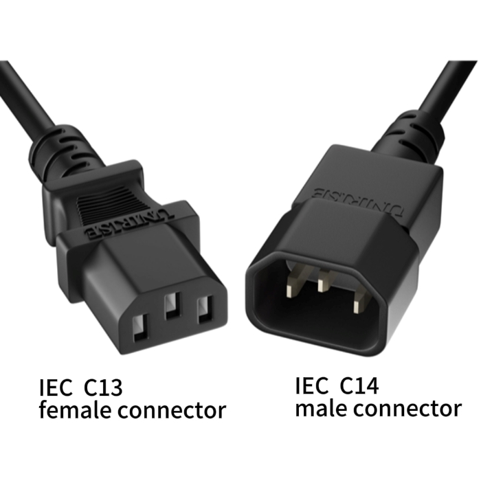
Common IEC 60320 connector ratings and applications (always
|
Connector Type (Female/Male) |
Rated Current (International/North American) |
Typical Applications |
|
C13 / C14 |
10A (IEC) / 15A (UL) |
Desktop PSU, Monitor, Printer |
|
C15 / C16 |
10A / 15A |
High-temperature environments (e.g., electric kettles, high-performance switches) |
|
C19 / C20 |
16A (IEC) / 20A (UL) |
Servers, blade racks, high-power UPS |
Are AC Power Cords Interchangeable? (IEC Type + Wire Gauge
IEC AC power cords are often interchangeable when (1) the IEC coupler type matches (e.g., C13 to a C14 inlet), (2) the cord is properly certified for your region, and (3) conductor gauge and temperature rating meet the load. This does not
• Connector Standard Matching: The device-end connector (e.g., IEC C13) must match the power supply unit's interface. For example, a standard desktop PC using a C13 connector can use any power cord compatible with that interface.
• Wire gauge (AWG) matters: A lower AWG number (e.g., 14 AWG)
• Rated Current Considerations: Always verify that the power cord's voltage rating and rated current meet the device's requirements. For instance, high-power workstations should use C19 connectors with appropriately rated cords, not standard C13 cords.
• Regional plug variations: In North America, the common
In summary, power cord interchangeability depends on the IEC interface, AWG gauge, and rated current. Users should select certified products and avoid mixing cables with different specifications to ensure stable, safe system operation.
Internal PC Power Connectors Overview (ATX Standards)
Modern ATX power supplies deliver multiple DC rails to
Understanding the connector type, keying, and pin function helps prevent misplugging and damage during assembly or troubleshooting. This section focuses on two core connectors linking to the motherboard power interface, detailing their pin definitions, power roles, and key safety considerations for plugging and unplugging. For a broader board-level overview beyond power headers alone, see types of connectors on the motherboard.
Motherboard Power: The 24-Pin ATX Connector
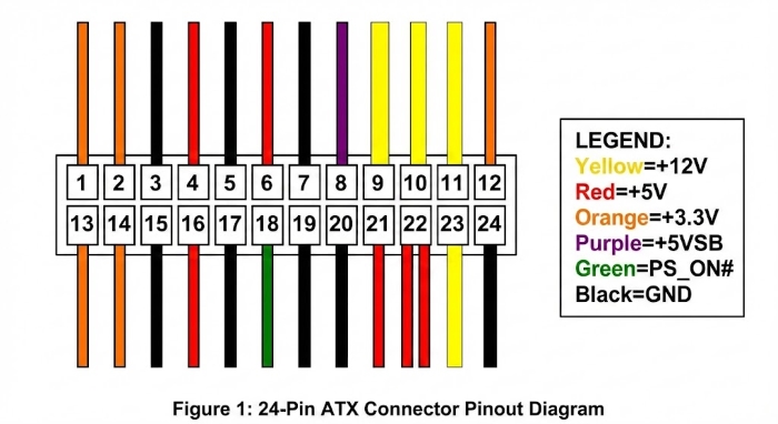
The largest and most central power connector on the motherboard is the 24-pin ATX connector, which powers nearly all motherboard components except the CPU. Modern ATX power cables commonly use a 20+4-pin connector design: a single 20-pin module paired with a detachable 4-pin module. This design ensures perfect compatibility with older motherboards that require a 20-pin power connector, providing excellent backward compatibility.
Key signals/rails on the 24-pin ATX connector include:
• +3.3V (Orange): Primarily powers legacy PCI devices, certain chipsets, and memory modules.
• +5V (Red): Powers USB ports, logic circuits in some hard drives, and legacy peripherals.
• +12 V (Yellow): Powers the PCIe slot’s 12 V supply, fans/pumps, and serves as an input to onboard DC-DC regulators
•+5 VSB (Purple): Standby rail that remains active when AC
•PS_ON# (Green): Active-low enable signal; the motherboard
• GND (Black): Ground line, providing a return path for all voltages.
•12 V (Blue, optional on many modern PSUs): Less common today, but may exist for legacy/compatibility needs.
CPU Power: EPS12V 4-Pin & 8-Pin Connectors
The interface dedicated to CPU power is commonly referred to as the EPS12V connector. It supplies power to the CPU Voltage Regulation Modules (often referred to as VRMs), which convert the 12V input into the core voltages required by the CPU. As CPU power demands increased, the power connector evolved from the early 4-pin design to the current mainstream 8-pin configuration (typically provided as a 4+4 pin setup) to handle higher current loads.
Keying (anti-misplug) tip:
This is one of the most error-prone steps during assembly. The CPU 8-Pin (EPS12V) connector and the graphics card's PCIe 8-Pin connector appear similar, but they are not interchangeable. The core distinction lies in their anti-misinsertion design:
• CPU 8-Pin (EPS12V): A two-part 4-pin module where both plastic terminal housings feature a square + semicircular shape combination.
• PCIe 8-Pin: Features a square + inverted trapezoid shape.
Warning: Never force a PCIe cable into the CPU connector!
Although the connector may partially insert if forced, the pins function differently, and misplugging can damage the PSU, motherboard, CPU, or GPU. Never force the connector; confirm
Graphics & Peripheral Power Connectors
After successfully powering the motherboard and CPU, the next focus is on peripheral interfaces that directly drive high-performance hardware and storage devices. Modern ATX power supplies feature a set of dedicated internal power cables to ensure efficient Power Delivery for components such as graphics cards, hard drives, and optical drives. Correctly identifying and using these cables is crucial for ensuring system stability, preventing overloads, and achieving the full power budget. This section details power-supply standards for graphics cards and storage devices, and addresses common questions about interface identification. ...For readers who also want a broader overview beyond power interfaces, see our guide to computer cable connector types.
GPU Power: PCIe 6-Pin, 8-Pin & 12VHPWR Identified
Discrete graphics cards often require more than the 75
• PCIe 6-Pin Connector: Provides up to 75 W of additional
• PCIe 8-Pin Connector: Provides up to 150 W of additional power.Combined with the PCIe slot’s 75 W, a single 8-pin + slot budget is commonly treated as up to 225 W (always follow
• PCIe 6+2-pin: This universal design allows the 2-pin section to be detached from or combined with the 6-pin main body. It functions as a 6-pin connector or can be merged into an 8-pin connector, ensuring maximum compatibility.
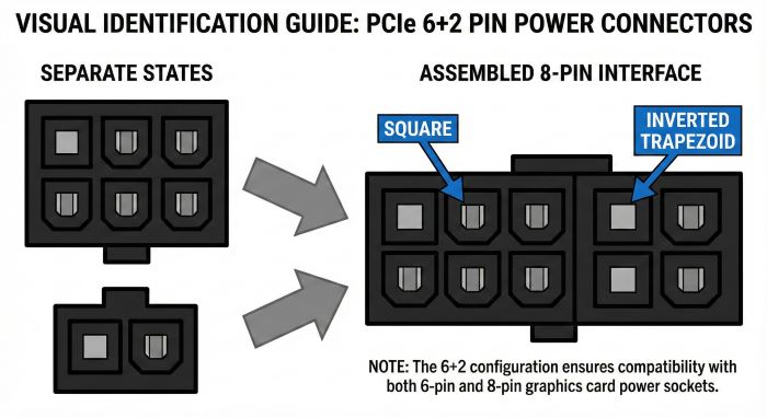
How do I identify the correct power connector for my graphics card?
1. Check the graphics card specifications: First, consult the graphics card manual or official specifications to confirm the required power connector type and quantity (e.g., 1x 8-Pin, 2x 8-Pin).
2. Physical Identification: The PCIe 6+2 pin connector features a distinct anti-misinsertion design with a "square + inverted trapezoid" terminal shape. This differs fundamentally from the CPU 8-Pin's "square + semicircle" configuration—never confuse the two.
3. Power Calculation: Ensure your power supply has sufficient +12V output capacity and the corresponding number of connectors to meet the graphics card's total power budget.
Latest 12VHPWR Connector:
To meet the power demands of next-generation high-performance graphics cards (e.g., NVIDIA RTX 40 Series), the ATX 3.0 standard introduces the 12VHPWR connector. This 16-pin connector (12 power contacts + 4 sense contacts) enables
Storage Power: SATA vs. Molex (Peripheral 4-pin)
1. Form Factor and Design:
• SATA Power Connector: Features a flat "L" shape design with excellent anti-misinsertion protection, minimizing incorrect plugging. Cable ends commonly employ either molded or crimped construction; reliability depends more on terminal material, crimp quality, wire gauge, and thermal design than the manufacturing process itself.
• Molex 4-Pin Peripheral Connector (commonly known as the large 4-pin): Typically employs a friction-fit structure, with insertion/removal resistance varying from tight to loose. Poor contact may cause a voltage drop and an increased risk of overheating. For a deeper explanation of naming, common use cases, and how this legacy plug differs from newer interfaces, read what a Molex connector is.
2. Power Supply Voltage:
• SATA: Provides +12 V, +5 V, and +3.3 V (many drives do not use the +3.3 V pins, but they are part of the SATA
• Molex: Provides only +12V and +5V.
3. Safety: For both SATA and Molex, increased contact resistance (due to loose connections, oxidation, or poor crimping) may cause overheating risks. Prioritize certified cables/connectors with appropriate gauge wire and reliable terminals. Avoid prolonged full-load operation with low-quality adapters.
Regarding Floppy (Berg) Connectors:
This is a smaller 4-pin connector formerly used for floppy drives and is now uncommon. It does not mate with SATA power
SATA Power Connector vs. Molex 4-Pin Connector Comparison Table:
|
Feature |
SATA Power Connector |
Molex 4-Pin Connector |
|
Physical Form |
Flat, L-shaped anti-misinsertion design (15-pin) |
Rectangular, large cylindrical pins (4-pin) |
|
Primary Voltage |
+3.3V, +5V, +12V |
+5V, +12V |
|
Key Safety Features |
Molded, secure fit, no exposed contacts |
Crimped, prone to loosening, no locking tabs |
|
Typical Connected Devices |
Modern HDD/SSD drives, optical drives, and RGB controllers |
Chassis fans, water pumps, legacy IDE hard drives, auxiliary power connectors |
|
Maximum Current/Power Reference |
Terminal and cable specifications vary significantly by manufacturer. Refer to the rated current, temperature rise, and wire gauge requirements in the cable/connector datasheet. For adapter cables (especially multi-port adapters), allow for a conservative margin. |
Varies by connector, pin |
Modular PSU Cables: A Critical Safety Warning
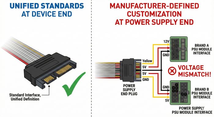
For users seeking tidy cable management, fully modular power supplies are an excellent choice. They allow you to connect only necessary cables, significantly optimizing internal case space and airflow. However, this flexibility masks a critical yet often overlooked safety hazard: the pin layouts on the power supply (PSU) side of fully modular cables are not universal across brands or even within different series from the same brand—meaning they are not interchangeable! Blindly mixing cables is one of the most common causes of instant hardware failure. This section delves into the core of this risk and answers a critical, frequently asked question: "Are all modular cables the same?"
Why Modular Cables Are Not Interchangeable
Rule of thumb: Do not mix modular PSU cables across brands or PSU series unless compatibility is explicitly documented
Fatal Consequences:
Mixing cables means that a SATA cable designed for Power Supply A might have its "12V" pin located at pin 3. When plugged into Power Supply B, pin 3 of B's modular connector might output "5V" or even "ground."Connecting this cable to your solid-state drive would deliver 12V directly to circuits designed for only 5V, causing a catastrophic electrical short circuit. This instantly destroys the drive and may also damage the motherboard or other components. Similar tragedies can occur with the motherboard's 24-pin or CPU's 8-pin cables, with equally severe consequences.
Safety Guidelines and Verification Methods:
1. Iron Rule: Use only the cables supplied with the original power supply. Keep all modular cables provided with the PSU, label them, and never mix them with cables from other power supplies.
2. Exceptions: Only third-party cables that are explicitly
3. How to Test (Advanced): If you doubt a cable's origin, the only reliable verification method is to use a multimeter's "continuity test" or "resistance measurement" function. Check pin continuity at both ends of the cable (device side and power supply side), one pin at a time, cross-referencing against your power supply's official pinout diagram. Note: Some cables may incorporate internal capacitors for filtering, which can result in non-zero resistance readings. Be sure to distinguish this during measurement.
Troubleshooting & Selection Guide
When your computer fails to boot, restarts unexpectedly, or crashes under heavy load, the power supply system is often the primary suspect. Learning to systematically troubleshoot power supply issues not only helps pinpoint problems quickly but also prevents unnecessary hardware replacements. Simultaneously, selecting the right power supply for your system is fundamental to ensuring long-term stable operation. This section provides a troubleshooting process from basic to advanced levels, along with key power supply selection recommendations, helping you ensure every connection from wall outlet to chip is safe and reliable.
Steps: How to Test if Connectors are Supplying Power
When your computer fails to power on, following a troubleshooting approach from simple to complex is crucial.
Step 1: Check Physical Connections
The most common issue is loose connections. After shutting down and disconnecting the power supply, verify that all internal cables are fully inserted and locked into place. Pay special attention to:
• 24-Pin Motherboard Connector: Press firmly until the latch clicks into place.
• SATA power connectors: Ensure they are fully seated; they should not come loose with a slight tug.
• CPU 4+4 Pin and PCIe 6+2 Pin connectors: Ensure both sections are fully merged and inserted.
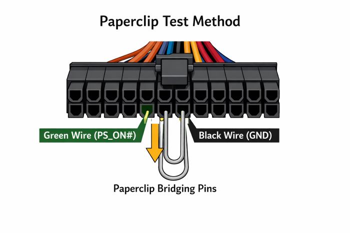
Step 2: Isolated Power Supply Test (Paperclip Test)
This step isolates the power supply for testing outside the system.
1. Disconnect the power supply from all components, including the motherboard and hard drives.
2. Locate the green wire (PS_ON#) and any black wire (GND, ground wire) on the 24-pin motherboard connector.
3. Straighten a paperclip and bend it into a U-shape. Bridge PS_ON# (green) to GND (black) on the 24-pin connector to command the PSU to turn on (use proper insulation and follow
4. Connect the power supply to mains power and turn on its rear switch. "If the power supply fan spins, it typically indicates the power supply has the potential to start up. However, this does not provide a stable voltage under load, acceptable ripple, or proper protection functions. For troubleshooting, it is recommended to proceed with a multimeter/power supply tester for load testing. Caution: This procedure carries risks. Ensure hands are dry and the paperclip contacts only the designated pins.
Step 3: Precise Voltage Measurement (Multimeter Test)
If the power supply passes the jumper test but the system remains unstable, abnormal output voltage may be the cause.
1. Using a multimeter: Select the DC voltage (V DC) range and choose a range above 12 V (e.g.,20 V or auto-range).
2. With the power supply connected to a load (or using a power supply tester), touch the black probe to any black wire (GND). Touch the red probe to the yellow wire (+12V), the red wire (+5V), and the orange wire (+3.3V), respectively, for measurement.
3. Compare the measured values with the ATX standard voltage tolerance range. For example, +12 V should be measured between
|
Voltage Rail |
Nominal Voltage |
Minimum Allowable Value (-5%) |
Maximum Allowable Value (+5%) |
Typical Application |
|
+12VDC |
+12.00 V |
+11.40 V |
+12.60 V |
CPU, Graphics Card, Hard Drive Motor, Fan |
|
+5VDC |
+5.00 V |
+4.75 V |
+5.25 V |
SSD circuitry, USB devices, logic circuits |
|
+3.3VDC |
+3.30 V |
+3.14 V |
+3.47 V |
Memory, M.2 SSD, Motherboard Chipset |
|
+5VSB (Standby) |
+5.00 V |
+4.75 V |
+5.25 V |
USB Power Supply During Shutdown, Wake-Up Function |
PSU Selection: Wattage, Connectors & Topology
1. Calculate total power consumption and select rated power
• Basic calculation: Sum the typical power consumption (TDP/TBP) while accounting for the Wire Gauges used in your high-draw lines, then add a margin of approximately 100-150W for the motherboard, hard drives, etc. Online power calculators can assist.
• "Sweet Spot" Wattage: Add a 20%-30% margin to the calculated total power consumption. This ensures the PSU operates within its most efficient range (typically 40%-60% load) and allows room for future upgrades and transient power spikes (e.g., GPU power spikes).
2. Verify Essential Connector Quantities.
• Motherboard: 1 x 24-pin.
• CPU: Determined by the motherboard's CPU power connectors—may require 1 x 8-pin (4+4) or 2 x 8-pin connectors.
• Graphics Card: Verify sufficient PCIe 6+2-pin connectors based on the card's requirements (e.g., high-end cards may need 3x 8-pin connectors).
• Storage & Peripherals: Verify sufficient SATA power connectors.
3. Understanding Single-Rail vs. Multi-Rail 12V Design
This is a critical consideration when handling high-power graphics cards, especially models with transient power spikes.
• Multi-rail 12V: The power supply's +12V output is divided into multiple rails, each with independent overcurrent protection (OCP). This design prevents overload on a single rail. However, for extremely high-power graphics cards, triggering protection on a single rail may cause a black screen and reboot.
• Single-rail 12V: All +12V current shares a single overcurrent protection threshold. This provides greater current flexibility for high-performance graphics cards and is less prone to triggering protection during transient loads, making it the mainstream choice for modern high-performance power supplies.
Why Source Connectors from Unikeyic?
After understanding the complex world of PC power supply connectors and safety standards, ensuring the quality and reliability of the connectors themselves is the crucial final step—whether for repairing damaged cables, customizing modular cables, or assembling small-batch devices. Substandard counterfeit connectors—whose crimp terminals may use inferior copper or poor plating—can cause excessive contact resistance. Over time, this can lead to overheating, melting, or even fires, completely negating the safety protections provided by proper use guidelines. Therefore, sourcing electronic components from trusted suppliers is fundamental to project success and equipment safety. If you require connector housings or crimp terminals for repairs or custom wiring harnesses, search Unikeyic’s inventory by brand/part number and submit an RFQ
Genuine Assurance, Safety Foundation
We understand that safety is paramount. Unikeyic can help source connectors from major manufacturers (e.g., TE Connectivity, Molex, and Amphenol) with traceable documentation when available. For cable builds,
For common connector housings, crimp terminals, and related
Completing a cable fabrication or repair project often requires multiple components and tools. At Unikeyic, you can source everything in one place. We not only offer a wide range of connectors but also provide matching high-quality cables, professional crimping tools, and other auxiliary materials. Additionally, we support BOM (Bill of Materials) matching services. Simply provide your list of required components, and our expert team will quickly match and procure them, significantly boosting efficiency. This allows you to focus your energy on the creative process and solving problems at hand.