Power Plug Connector Types: NEMA, IEC & Global Standards
| Table of Contents |
The Basics: AC vs. DC Power Connectors
Power plug connector types vary globally and are primarily categorized into two main types: alternating current (AC) and direct current (DC). Understanding the differences, standards, and applications of these connectors is crucial for selecting suitable equipment and ensuring electrical safety.
AC Connectors: The Standard from Wall Outlet to Device
AC connectors transmit power from wall outlets to devices or power supplies, typically at 100-240 V AC (region-dependent). Because they interface with mains voltage, AC connectors must comply with applicable safety standards and carry required approvals/markings for the target market (e.g., UL/CSA listing in North America, CE marking in the EU). Common global electrical plug connector types include:
| Type | Region of Use | Features |
| Type A/B | North America, Japan | Two-prong flat plug (A) or with grounding pin (B) |
| Type C/E/F | Most of Europe. | Two-pin round plug, some with grounding |
| Type G | United Kingdom, Ireland | Three-pin rectangular plug, with fuse |
| Type I | Australia, New Zealand (and some other regions) | Three flat pins in a V-shaped arrangement (with/without earth, depending on plug) |
These plugs are designed to accommodate regional voltage differences (110 V or 220-240 V) and safety requirements, so travel adapters are often needed when traveling abroad.
DC (Direct Current) Connectors: Power Transmission from Adapter to Device
DC connectors typically carry lower voltages (commonly 5-48 V DC, depending on the power source and the deviceʼs input requirements) and come in various shapes, primarily including:
• Barrel Jack: Widely used in monitors, network equipment, etc., available in various sizes (e.g., 5.5mm x 2.1mm).
• USB Type-C: A universal standard for modern mobile devices and laptops, supporting high-power fast charging and data transfer.
•Proprietary DC Plugs: Examples include round or square power connectors for laptops.
Although DC connectors operate at lower voltages, they must still match the device's voltage and current requirements to prevent damage.
The diagram below illustrates the complete power chain, which converts high-voltage AC to low-voltage DC and ensures safe transmission. Each step relies on the corresponding power connector type.
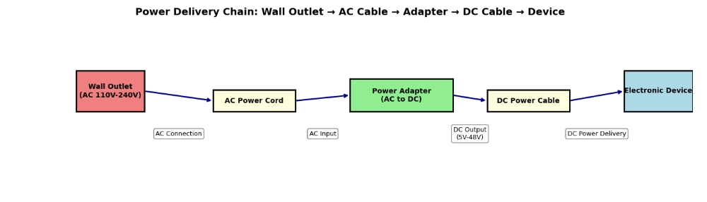
Therefore, selecting the appropriate power connector is critical for both device compatibility and electrical safety, whether for AC wall outlets or DC device interfaces. When using electronic devices globally, always verify local voltage standards and plug types, and prioritize products with safety certifications.
● The Difference Between AC Plugs and DC Jacks
These two connector types exhibit fundamental differences in design, application, and safety standards, directly impacting device design, system integration, and global compliance.
AC plugs serve as the interface connecting devices to wall outlets in the mains power grid, transmitting high-voltage, directionally alternating current. Their primary design considerations are personal safety and fire prevention. Due to direct connection to high voltage, their insulation performance, material flame-retardant ratings, and mechanical strength are strictly regulated by international standards. Common IEC 60320 connectors (e.g., C13/C14 used for computer power cords) serve as a universal solution for device-end wall outlets globally, though wall socket types still vary by country/region (e.g., Type A, G, I). To learn more about computer power connector types (including IEC C13/C14, C19/C20, etc.) used in PC setups—from wall outlets to power supplies and inside computer cases—along with their applications and key selection criteria, continue reading this article.
DC plugs are used internally within devices or at terminals to transmit low-voltage, directionally constant direct current, typically sourced from power adapters or batteries. Polarity is a critical consideration—reversing positive and negative terminals can cause permanent device damage. Consequently, many DC connectors incorporate anti-misinsertion features. The most common example is the barrel connector (cylindrical connector), where the inner pin and outer sleeve define positive and negative polarity, respectively. In recent years, the USB-C interface has become the most important DC connection standard in consumer electronics due to its high-power transmission capability (PD protocol) and the convenience of being non-polarized (reversible plug).
| AC Plug vs DC Plug: Detailed Comparison Chart | ||
| Comparison Dimensions | AC Plug (Alternating Current Connector) | DC Plug (Direct Current Connector) |
| Voltage Range | High Voltage: Commonly 100 V-240 V (mains power standard) | Low Voltage: Commonly 3 V-48 V, USB PD up to 240 W (48V x 5A) (EPR) |
| Current Type | Current direction and magnitude periodically alternate | Current direction and magnitude remain constant |
| Typical Applications | Home appliances, industrial equipment, lighting systems—any device drawing power directly from wall outlets | Consumer electronics (mobile phones, laptops), routers, surveillance equipment, and power supply within PCB boards |
| Standardization Level | Highly standardized but varies by region: • IEC 60320 (C13/C14, etc.) • National plug configurations (US, EU, UK, etc.) |
Partially standardized, diverse forms: • Barrel connectors (various sizes) • USB (Type A, Type C) • Industry-specific interfaces (e.g., 5521) |
| Safety requirements | Extremely stringent requirements necessitate strict insulation, high-voltage resistance, spark-proofing, and compliance with safety certifications such as UL, CE, and CCC | Relatively lower requirements, but overcurrent protection and reverse polarity protection design must be ensured |
| Core Design Considerations | Safety isolation, electric shock prevention, and compatibility with the physical specifications of wall outlets in different countries | Compact size, efficiency, low cost, correct polarity alignment |
| Typical Connector Form Factors | Fixed form factors, predominantly flat or cylindrical pins/sockets | Diverse forms, including classic round-hole plugs (cylindrical), USB ports, terminal blocks, etc. |
IEC 60320 Connectors (For IT & Appliances)
IEC 60320 specifies appliance couplers typically rated up to 250 V, with current ratings that vary by connector type (commonly up to 16 A; some variants are rated up to 20 A—always verify the specific datasheet). Its core advantage lies in "device-side globalization": Equipment manufacturers need only install standard male connectors (e.g., C14, C20) on their products. End-users can then select power cords with corresponding plug standards (e.g., cables with C13 female connectors) based on their country or region's grid specifications. This design significantly simplifies product design, production, inventory management, and global sales.
In IEC 60320 naming, even numbers typically refer to appliance inlets (male), and odd numbers refer to connectors (female). Male appliance inlets (MAI) are typically fixed to the appliance housing, while female connectors (FC) are located at the end of the power cord.
| Key IEC 60320 Connector Types and Application Pairing Chart The chart clearly illustrates the most common pairs of appliance couplers, their pairing relationships, physical characteristics, and typical application scenarios, facilitating quick identification and selection. |
||||
| Device-Side Male Inlet | Power Cord End Female Connector | Common Names and Appearance Features | Key Electrical Parameters | Typical Application Devices |
| C14 | C13 | "Pin-shaped connector"/"Computer plug" Three-pin, grounded, rectangular profile |
C14 (inlet) / C13 (connector): typically 10 A; temperature rating depends on the temperature class (commonly 70°C for standard versions—verify the cordset/inlet rating) | Desktop computers, monitors, printers, audio equipment, and office appliances |
| C6 | C5 | "Mickey Mouse Head" (Cloverleaf) Three-prong, grounded, triangular arrangement |
Typically 2.5 A or 10 A | Laptop power adapters, projectors, and some monitors |
| C8 | C7 | Figure-8 Two-pole, non-grounded, shaped like an "8." |
Typically 2.5 A, no grounding | Low-power appliances: desk lamps, Bluetooth speakers, chargers, game consoles |
| C20 | C19 | "High-power pin-shaped connector" Three-pin, grounded, square, significantly larger than C13/C14 |
Typically rated at 16 A or 20 A | Rack-mounted servers, high-end workstations, high-power PDUs, UPS systems |
Key Differences Explained: C13 vs. C15 (High-Temperature Version) Connectors
Distinguishing standard C13 from high-temperature C15 connectors is critical, as incorrect interchangeability may pose safety hazards. Though visually similar, their core difference lies in temperature ratings.
• C13 Connector: Standard model with a typical maximum operating temperature of 70°C. This is the most common type, widely used in devices with low heat generation, such as computers and monitors.
• C15 Connector: High-temperature “hotcondition” variant with a maximum temperature rating of 120°C (commonly referenced for standard C15). Designed for high-heat-generating devices like electric kettles, tea makers, network switches, and server rooms with elevated temperatures.
Key Identification Feature: Notch Design
The most intuitive physical distinction lies in the notch design of the female connector:
• C13 female connector: Symmetrical square notches on both sides.
• C15 female connector: The notches on both sides are asymmetrical—one side is square, while the other features a deeper "V"-shaped or trapezoidal notch.
The C15 female connector is designed to mate with the C16 male connector (the high-temperature version of C14), but it can also physically accommodate a standard C14 male connector. Crucially, however, a standard C13 female connector cannot be inserted into a C16 male connector. This design implements a fail-safe principle: "High-temperature cables can be used with standard equipment, but standard cables cannot be used with high-temperature equipment."

● Common Types: C13, C5, and C7 Explained
In the field of connecting electronic devices to power sources, the IEC 60320 standard defines globally applicable appliance coupler specifications. Among these, C13, C5, and C7 are the three most common types, widely recognized for their distinctive shapes and application characteristics. Whether it's the C5, often called the "cloverleaf/Mickey Mouse connector," the C7 with its "figure-eight shape," or the industry-standard C13, each serves its purpose within the IEC 60320 framework. Accurately understanding their differences in grounded and ungrounded characteristics is a crucial step in ensuring the safe and reliable operation of electronic devices.
C13 is the female connector at the power cord end. Standard C13 power cords serve as the bridge connecting desktop computers, monitors, and servers to power sources. This grounded connector provides vital safety protection. Typically rated at 10A, it suits most office and home IT equipment. Primary applications include desktop computers, monitors, printers, audio equipment, and server power inputs (paired with PDUs). ...For a broader overview of computer cable connector types used across PCs and related devices, see our detailed guide.
C5 is the familiar "cloverleaf/Mickey Mouse connector" found on laptops, instantly recognizable to users due to its distinctive appearance. Its three pins are arranged in an equilateral triangle, resembling the outline of Mickey Mouse's head or a cloverleaf, earning it the industry nicknames "cloverleaf connector" or "Mickey Mouse connector."Like C13, C5 is a grounded connector offering high safety. Typically designed more compactly with a common 2.5A current rating, it is optimized for external power adapters of portable devices. Primary applications include laptop power adapters, LCD monitors, projectors, and certain game consoles.
C7 is an "8-shaped connector" for low-power devices, becoming the standard configuration for many low-power consumer electronics due to its minimalist design. It is commonly called the "figure-eight connector" because its connector profile resembles a smooth "8" shape. This is a non-grounded two-pole connector. It contains only live and neutral wires, lacking a protective grounding pin. This design enables a slimmer profile, making it suitable for devices meeting double insulation (Class II) safety standards. Users must verify whether their equipment requires grounding protection during selection. Primary applications include slim laptops, speakers, desk lamps, DVD players, TV set-top boxes, and various compact chargers.
The table below clearly contrasts the core differences between these three common connectors, helping you make the right choice quickly.
| Features | C13 Connector | C5 Connector | C7 Connector |
| Common colloquial names | Pin-shaped connector | Cloverleaf/Mickey Mouse connector | Figure-8 connector |
| Grounding Protection | Grounding (3-pin) | Grounded (3-pin) | Non-grounded (2-pin) |
| Rated Current | Typically 10 A | Typically 2.5 A | Typically 2.5 A |
| Key Features | Versatile, rugged, high-load capacity | Compact, portable, specialized | Slim, low-cost, for Class II equipment only |
| Typical Voltage | 100-240 V AC | 100-240 V AC | 100-240 V AC |
| Typical Applications | Desktop computers, servers, monitors | Laptop adapters, projectors | Small appliances, audio equipment, chargers |
Core Safety Tip: Choosing Between Grounded and Ungrounded
Understanding the difference between grounded and ungrounded connectors is crucial for safe selection. Grounded connectors (C13, C5) provide electric shock protection via an additional ground wire and are mandatory for metal-cased or Class I appliances. Ungrounded connectors (C7) are only suitable for plastic-cased, double-insulated Class II equipment. Incorrectly using ungrounded connectors on devices requiring grounding poses serious safety hazards.
● High-Power Applications: C19 & C15 Connectors
In demanding high-power and high-temperature applications, the C19 and C15 connectors—specialized high-temperature connectors—form the foundation for safe and reliable electrical connections. Proper understanding and selection of these connectors are critical for ensuring stable system operation, preventing overheating risks, and guaranteeing operational safety.
The C19 is a connector designed specifically for high-current applications, featuring distinct physical characteristics and performance compared to standard connectors.
• Visual Identification: The C19 (female connector) features a square profile and is noticeably larger than common C13/C14 connectors. This design provides a greater contact area and a more robust physical structure to handle high-current transmission.
C15 connectors are commonly referred to as high-temperature connectors. They incorporate critical enhancements over standard C13/C14 designs to withstand elevated temperatures generated by equipment or the surrounding environment.
• Core Electrical Parameters: Its key advantage lies in a higher rated current, typically 16A, with some models reaching 20A. This enables safe power handling up to 4,000 W at 250 V (based on 16 A x 250 V; real-world limits depend on derating and temperature class), doubling the capacity of standard 10A C13 connectors.
C15 connectors are commonly referred to as high-temperature connectors. They incorporate critical enhancements over standard C13/C14 designs to withstand elevated temperatures generated by equipment or the surrounding environment.
• Visual Identification (Key Difference): The C15 female connector closely resembles the C13, but features one crucial distinction—its side notches are asymmetrical. One side has a square notch, while the other has a deeper V-shaped (or trapezoidal) notch. This serves as a physical "foolproof" identifier specifically designed for high-temperature applications.
• Core Electrical Parameters and Design: The C15 connector's primary advantage lies not in higher current ratings but in its superior temperature tolerance. While standard C13 connectors are commonly rated to 70°C, C15 connectors are commonly rated to 120°C (and C15A variants to higher ratings); always check the exact temperature class on the datasheet, and even higher temperatures (e.g., 155°C for C15A). This effectively prevents fire or short-circuit risks caused by cable insulation softening or melting in high-temperature environments.
| Features | C19 Connector | C15 Connector |
| Design Objectives | High current (high power) handling | Withstand high temperatures |
| Key Parameters | High-rated current (16 A/20 A) | High operating temperature (≥120°C) |
| Physical Characteristics | Square, large volume | Similar to C13, but with an asymmetrical V-shaped notch |
| Physical Compatibility | Incompatible with C13/C14; larger interface | C15 plugs fit into C14 sockets, but C13 plugs do not fit into C16 sockets |
| Typical Applications | Cabinet power distribution units (PDUs), servers, and high-power UPS systems | Electric kettles, high-heat-generating network equipment, kitchen appliances |
NEMA Connectors (North American Standards)
NEMA (National Electrical Manufacturers Association) connectors represent the standard power plug and socket specifications widely adopted across North America (including the United States, Canada, Mexico, etc.). Through its logical naming conventions and diverse types, the NEMA connector system addresses a broad spectrum of electrical needs—from residential applications to industrial facilities. This standardized framework ensures safe and reliable connections between equipment and power grids. Its distinctive naming rules and typology are crucial for device manufacturing, export compliance, and everyday usage.
NEMA Naming Convention Analysis
NEMA device configurations are commonly written as NEMA X^YYP (plug) or X^YYR (receptacle), with “L” indicating a locking type (e.g., L5-30P).
First digit (voltage rating): Commonly, "1" denotes 125 V, "5" denotes 125 V (with grounding), and "6" denotes 250 V. For example, NEMA 5-15P is designed for 125V systems.
Second digit (current rating): Indicates the connector's rated amperage. For example, "15" denotes 15 A, while "20" denotes 20 A.
Suffix letters:
• P (Plug): Indicates the plug, the movable end connected to the power cord.
• R (Receptacle): Indicates a receptacle, the fixed end installed on a wall or equipment.
Prefix "L": Denotes a locking plug. For example, NEMA L5-30P is a 125 V, 30 A plug with a locking mechanism, widely used in industrial settings requiring anti-disconnection features.
Common NEMA Connector Types
The NEMA standard encompasses a broad product range from household general-purpose to industrial-specific types. The following are the most common types:
| Non-Locking: The most common type for everyday use, featuring straight pins that rely on friction for retention. | |||
| Type | Pin Configuration and Appearance | Rated Current | Typical Applications |
| NEMA 1-15P/R | Two parallel flat pins (one live, one neutral), no ground | 15 A | Vintage small appliances and lighting fixtures (phased out in new construction due to lack of grounding) |
| NEMA 5-15P/R | Two parallel flat prongs + one round grounding pin. This is the standard American three-prong plug. | 15 A | The modern North American standard is used for most household appliances, computers, and office equipment |
| NEMA 5-20P/R | One neutral pin is a straight blade, one live pin is a "T"-shaped blade perpendicular to the neutral, plus a grounding pin | 20 A | For devices requiring higher current, such as certain kitchen appliances and commercial equipment. The receptacle is compatible with 5-15P plugs. |
| Locking Type ("L" Series): These connectors require a twist after insertion to mechanically lock the plug in place, creating a self-locking connection that prevents accidental disengagement for enhanced safety. | |||
| Type | Pin Configuration and Appearance | Rated Current | Typical Applications |
| NEMA L5-15P/R | Round interface with curved locking groove and grounding pin | 15 A | Professional audio equipment and small tools requiring reliable connections |
| NEMA L5-30P/R | Circular interface, larger than L5-15 with thicker pins | 30 A | Portable generators, machine room PDUs (power distribution units), stage lighting, and industrial equipment |
| NEMA L6-30P/R | 250 V class locking connector; typically two hot conductors plus protective earth (no neutral) | 30 A | High-power motors, welding machines, and data center high-voltage AC inputs |
Core principle of pin shape variation: As shown in the NEMA connector chart above, both non-locking straight pins and self-locking round pins increase in size and thickness with higher rated currents. This reduces resistance and heat generation, ensuring safe handling of greater currents.
Which safety standards apply to various power plug connectors?
NEMA connectors embody practical safety standards that collectively ensure fire resistance, electric shock protection, and overheating prevention during both normal operation and fault conditions.
Physical Design Safety: NEMA standards themselves dictate the mechanical dimensions, electrical clearances, and pin shapes for plugs and receptacles. For example, the T-slot on a NEMA 5-20R receptacle allows a 5-15P plug, but prevents inserting a 5-20P plug into a 5-15R receptacle, avoiding overload. Similarly, a 20A plug cannot be inserted into a 15A receptacle, creating a physical fail-safe design.
Material and Testing Certification: NEMA connectors must undergo rigorous testing and certification by third-party safety laboratories before market release. Key certifications include:
• UL Certification (Underwriters Laboratories): In North America, many products require approval by an NRTL (e.g., UL, ETL) depending on the product category and application. UL standards (e.g., UL 498) specify detailed safety requirements for receptacles and plugs.
• CSA Certification (Canadian Standards Association): Valid for the Canadian market.
• NRTL Certification (Nationally Recognized Testing Laboratory): For workplace equipment, OSHA mandates the use of electrical products certified by NRTLs (e.g., UL, ETL).
● Decoding NEMA Codes: 5-15P vs. 5-20P
Among North American standard power connectors, NEMA 5-15P and NEMA 5-20P are the two most common and easily confused plug types. The difference between NEMA 5-15P and 5-20P extends far beyond the 5-amp current rating indicated by the numbers. Through the shape of the live pin (flat vs. T-shaped) and its mating with the T-slot receptacle, they form an intuitive and effective electrical safety error-proofing system. How does the unique T-slot receptacle design become crucial for a safe power supply?
Decoding NEMA Codes
The NEMA code itself serves as a concise technical specification. Taking "5-15P" and "5-20P" as examples:
• First digit "5": Represents the configuration type and voltage rating. Here, it denotes a "125V, grounded" connector series.
• The number after the hyphen (15 or 20): Clearly indicates the connector's current rating in amperes (A). This is the core performance difference between the two—the 5-15P is rated for a maximum of 15 A, while the 5-20P handles up to 20 A.
• Suffix letter "P": Stands for "Plug." Its counterpart is the "R" (Receptacle) found on wall outlets or power strips.
Therefore, "NEMA 5-15P" denotes a grounded plug rated for 15 amperes on a 125V circuit.
Key Feature Comparison Between 5-15P and 5-20P
Although both are used in 125 V systems and feature a grounding pin, they differ in one critical design aspect intended to prevent misuse.
| Feature | NEMA 5-15P (Standard US Plug) | NEMA 5-20P (High-Current Plug) |
| NEMA Code Meaning | 125 V, 15 A, Plug | 125 V, 20 A, Plug |
| Rated Current | 15 amps | 20 amperes |
| Live and neutral pins | Both pins are flat, straight pins | Neutral pin is a straight-through terminal; live pin is a "T"-shaped terminal perpendicular to the neutral pin (with a raised edge on one side) |
| Ground pin | A circular grounding pin, typically longer in length, ensures grounding occurs before power is applied | Equipped with circular grounding feet, with identical functionality and safety sequence. |
| Matching receptacle | Standard NEMA 5-15R receptacle (two parallel slots) | Dedicated NEMA 5-20R T-slot receptacle (one parallel slot + one "T"-shaped slot) |
| Physical Compatibility | Can be inserted into a 5-20R T-slot receptacle (utilizing the vertical portion of the T-shape) | Cannot be inserted into standard 5-15R receptacles (T-shaped tab blocked by parallel slots) |
| Typical Applications | Most household appliances, computers, monitors, mobile phone chargers, etc | Kitchen/Workshop High-power appliances (e.g., microwaves, portable air conditioners), certain commercial equipment, server cabinet PDUs |
Core Safety Design: The T-Slot Outlet's Foolproof Philosophy
The physical compatibility differences revealed in the table above exemplify a sophisticated safety "foolproof" design within the NEMA standard:
"Upward Compatibility" Design: A standard 15 A plug (5-15P) can be inserted into a 20 A T-slot socket (5-20R). This ensures ordinary devices can be temporarily used in sockets intended for high-power circuits, providing flexibility.
"Downward Blocking" Protection: A 20 A high-current plug (5-20P) cannot be inserted into a standard 15A socket (5-15R). This serves as the critical safety barrier, preventing a device designed for 20 A current from being connected to a socket potentially protected only by a 15 A circuit. This avoids risks of circuit overload, overheating, and even fire hazards.
Thus, the T-slot socket serves not only as a physical interface but also as a coded safety identifier. It enables system administrators to visually identify and distinguish the current rating and cable specifications behind the circuit based on the socket type.
● Industrial Twist-Lock Connectors
In industrial manufacturing, data centers, field operations, and various harsh environments, standard straight-plug power connectors often face risks of loosening or disconnection due to vibration, accidental pulling, or frequent plugging/unplugging. This can lead to production interruptions, equipment damage, or even safety incidents. To address this, industrial twist-lock connectors (such as the NEMA L series and corresponding IEC 60320 models) were developed. Through their unique rotational locking mechanism, these connectors elevate simple electrical connections into reliable mechanical interlocks. They not only meet the power-carrying demands of heavy-duty applications but also serve as proactive safety solutions against physical challenges like seismic resistance and disconnection prevention.In industrial and commercial settings where production continuity, equipment safety, and personnel safety are paramount, investing in the right self-locking connector system fundamentally provides indispensable insurance for ultimate power supply reliability.
Core Mechanism: How Rotary Locking Works
The fundamental difference between industrial self-locking connectors and household plugs lies in their locking mechanisms. Operation typically involves three steps:
• Align and Insert: Align the plug's pins with the corresponding receptacle holes and insert straight in.
• Rotational Locking: Once fully inserted, rotate the plug housing clockwise (typically 15-30 degrees). This engages internal latches or flanges within the plug with spiral grooves inside the socket.
• Mechanical Locking: Once rotated fully, the connector is physically locked in place and cannot be pulled out directly. To separate the plug and socket, the locking ring must be rotated in the opposite direction to release the mechanism.
This rotational locking mechanism creates a robust integrated mechanical and electrical connection that cannot be dislodged by external pulling forces alone, fundamentally eliminating the risk of accidental power disconnection.
Why are self-locking connectors essential for heavy-duty applications?
"Heavy-duty applications" carries dual meanings here: first, high-current, high-power electrical loads; second, demanding physical environments. Self-locking connectors are specifically engineered for such scenarios.
| Comparison Dimensions | Standard Non-Locking Connectors | Industrial Self-Locking Connectors |
| Connection Reliability | Relying on spring-loaded friction and insertion depth, susceptible to vibration and external forces | Achieves a rigid mechanical connection through rotational locking, offering extremely high reliability |
| Vibration resistance and anti-disconnection | Prone to loosening in sustained vibration or motion environments, leading to arcing, sparking, and power loss | Specifically designed for shock resistance; maintains a stable connection after locking, withstanding continuous vibration and impact |
| Electrical safety | Loosening may increase contact resistance, causing abnormal heating and posing a fire hazard | Locking ensures pins and sockets maintain optimal contact at all times, resulting in low contact resistance and stable temperature rise |
| Typical Applications | Fixed office and household appliances | Generators, welding machines, large machine tools, stage lighting and audio equipment, data center PDUs, and mobile vehicle power supply |
Primary Standards and Types of Industrial Self-Locking Connectors: NEMA L Series and IEC Interlocking Systems
Industrial self-locking connectors primarily adhere to two major standard systems, catering to different regional and electrical requirements:
NEMA L Series (North American Standard)
• Naming convention: e.g., L5-30P. L denotes locking, 5 indicates 125 V, 30 signifies 30 A, and P represents plug.
• Common models: L5-15 (125 V/15 A), L5-30 (125 V/30 A), L6-30 (250 V/30 A, non-grounded for two-phase power), etc. Higher numbers typically indicate larger size and current ratings for heavier-duty applications.
IEC 60320 Interlocking Connectors
• Incorporates mechanical locking mechanisms (e.g., latches, screw-lock sleeves) on top of standard connectors like C13/C19.
• Commonly used in professional medical, testing, and industrial equipment requiring international compatibility and reliable connections.
Global AC Plugs by Region (Type A to Type G)
Understanding diverse international power plug standards is fundamental to ensuring device compatibility and electrical safety in global electronics trade and usage. Different plug designs across countries stem from their respective grid development histories, safety regulations, and electrical standards. Grasping global AC plug variations is not only a technical necessity but also a critical factor for successful international market entry and user safety assurance.
Overview of Major AC Plug Types Worldwide
Although the International Electrotechnical Commission (IEC) does not mandate a unified global plug standard, it broadly classifies plug types alphabetically. Below are the most common types and their primary regions of use.
| Category | Design Features | Compliant Standards | Regions of Use | Voltage/Frequency |
| Type A and Type B (North American, Japanese Standards) | Type A: Two parallel flat blades, no grounding, typically rated at 15A. Type B: Adds a round grounding pin to the Type A configuration, forming a three-pin structure with two flat pins and one round pin |
Based on NEMA standards | United States, Canada, Mexico, Japan (Japanese Type A plugs feature two flat blades but with slightly different dimensions; Type B is also concurrently used domestically), etc | Typically 120 V / 60 Hz |
| Type C, E, and F (European Continental Standard) | Type C (Europlug): Two round pins, no grounding. Designed for compact size to fit various European sockets, but limited to low-power devices (typically under 2.5 A). Type E (French standard) and Type F (German standard/Schuko): Both feature two round pins with grounding. Type E achieves grounding through a dedicated grounding hole in the socket, while Type F (Schuko) uses metal spring clips on either side of the socket. Schuko (Type F) is the most widely used and preferred for medium-to-high power appliances in continental Europe |
Complies with CEE 7/xx series standards | Germany, France, the Netherlands, Sweden, and most other European countries (excluding the UK and Ireland) | Typically 230 V /50 Hz |
| Type G (UK, Ireland, etc. standard) | Features three rectangular flat pins arranged in a triangle. The plug incorporates an internal fuse. This design provides rapid circuit protection and user safety by melting in the event of equipment or cable failure | BS 1363 | United Kingdom, Ireland, Malaysia, Singapore, Hong Kong, etc | Typically 230 V /50 Hz |
| Type I (Australia, China, etc.) | Three flat prongs arranged in an inclined "eight" shape or near-V configuration | Australia follows AS/NZS 3112 standard; China follows GB 1002 and GB 2099.1 | Australia, New Zealand, China, Argentina, etc | Australia: 230 V / 50 Hz; China: 220 V /50 Hz |
How does a Type G power plug connector differ from a Type C connector?
The differences extend far beyond appearance, primarily in safety, structure, and application. Simply put, Type G is a fully functional plug system integrating multiple active and passive safety measures. At the same time, Type C is a simplified, non-grounded plug designed for low-power, portable devices.
| Comparison Dimensions | Type C (European two-pin) | Type G (UK Standard) |
| Physical Structure | Two round pins, no grounding | Three rectangular flat pins, including live, neutral, and ground |
| Grounding Protection | No grounding; intended solely for use with Class II equipment featuring double insulation | Grounding is provided for Class I appliances (metal casing) to prevent electric shock |
| Rated Current | Typically low (2.5 A), limited to low-power devices | Typically 3 A, 5 A, 13 A (via fuse replacement), supporting high-power appliances |
| Application Scenarios | Low-power appliances such as electric shavers and mobile phone chargers | Any household or industrial equipment, such as washing machines, refrigerators, and computers |
| Regional Distribution | Common in continental Europe, though gradually being replaced by Type E/F | United Kingdom, Ireland, and some former Commonwealth countries |
Global Plug Type Distribution and Electrical Parameters Quick Reference
The following table summarizes plug types and basic electrical parameters for major countries and regions:
| Country/Region | Primary Plug Type | Voltage | Frequency |
| United States, Canada | Type A, Type B (NEMA 5-15) | 120 V | 60 Hz |
| Japan | Type A, Type B | 100 V | 50 Hz (East)/60 Hz (West) |
| Germany, France, Spain, etc | Type C, Type F (Schuko), Type E | 230 V | 50 Hz |
| United Kingdom, Ireland | Type G (BS 1363) | 230 V | 50 Hz |
| Australia, New Zealand | Type I | 230 V | 50 Hz |
| China | Type I (GB standard) is typically cited as 220 V / 50 Hz | 220 V | 50 Hz |
| India | Type C, D, M | 230 V | 50 Hz |
| Brazil | Type N | 127 V / 220 V | 60 Hz |

Why do different countries use different power plug connector types?
Why is there such diversity in plug types worldwide? This is not merely a matter of design preference, but a complex outcome shaped by historical legacies, variations in voltage and frequency, and local safety philosophies.
Historical Development and Early Electrification: Countries developed independently during the early stages of electricity adoption, lacking international coordination. This created the "historical legacy" problem that remains difficult to unify today. For example, the fuse design in British plugs reflects a specific historical solution from Britain's post-war copper shortage period, where protecting cables helped conserve materials.
National Grid Standard Differences: Variations in voltage and frequency are the fundamental technical drivers behind differing physical plug designs. Core differences in voltage (e.g., 110-120 V vs. 220-240 V) and frequency (e.g., 50 Hz vs. 60 Hz) necessitate distinct insulation ratings and contact clearances, thereby influencing plug configurations.
Evolution of Safety Philosophy and Regulations: Facing identical technical challenges, nations developed distinct safety regulations based on accident experience and safety awareness, forming unique "safety philosophies" that ultimately manifested as physically diverse plug designs. For example, Germany's Schuko (European Standard Plug Type F) emphasizes side-mounted grounding, while France's Type E employs a protruding grounding pin—both reflecting different engineering safety approaches.
● Europe (Type C/F) vs. UK (Type G)
While serving the same electrification goals, Europe's Type C/F plug and the UK's Type G plug diverged onto distinct technical paths. The former prioritized efficiency and regional compatibility, while the latter established an ultimate safety benchmark centered on fuses—even at the cost of greater bulk and complexity.Within Europe's electrical connectivity landscape, European-standard plugs (represented by Type C and Type F) and British-standard plugs (Type G) embody two mature yet divergent design philosophies and safety standards. Despite geographical proximity and identical grid voltages (230V, 50Hz), these connectors exhibit fundamental differences in physical structure, safety mechanisms, and application scope.
European Continental Standard: Type C and Type F (Schuko) Plugs
European plugs serve as the universal standard across most continental European nations, primarily comprising the two-pin, ungrounded Type C and the grounded Type F (Schuko).
• Type C (European two-pin round plug)
Appearance: Two cylindrical pins arranged parallel, without a grounding pin.
Core Characteristics & Limitations: Suitable only for low-power devices with double insulation (Class II). Due to its non-grounded design, the rated current is typically limited to 2.5 A or below, restricting its use to low-power applications such as mobile phone chargers, electric shavers, and small lamps.
Design Intent: Prioritizes compactness and broad socket compatibility, fitting into multiple socket types across most European countries.
• Type F (Schuko - German Standard):
Appearance: Two cylindrical pins flanked by metal grounding spring clips on either side of the plug. Corresponding grounding clip slots are present on both sides of the socket.
Core Feature: Europe's most universal and safest grounded plug standard. Its name "Schuko" derives from the German "Schutzkontakt" (protective contact), emphasizing its core grounding protection function.
Safety Mechanism: Ensures reliable grounding through side-mounted spring contacts. This directs current safely to earth in case of insulation failure in metal-cased appliances, preventing electric shock.
Application Scope: Suitable for all Class I appliances requiring grounding protection, such as washing machines, refrigerators, computers, power drills, and other medium-to-high power devices.
British Standard: Type G (BS 1363) Plug
The British Standard plug (Type G) is widely recognized as one of the world's most rigorously designed consumer plug systems for safety. Its BS 1363 standard specifies multiple protections far exceeding basic connection functionality.
Appearance: Three rectangular flat pins arranged in an isosceles triangle configuration (ground pin at top, neutral and live pins below).
Core Safety Features:
Built-in replaceable fuse: Each plug integrates a standard-rated fuse (e.g., 3A, 5A, 13A). This unique design provides precise overcurrent protection for individual devices, preventing fires caused by equipment or cable failures.
Insulated Sheath: The straight-insert portion of the prongs is encased in insulating material, ensuring fingers cannot accidentally contact live prongs during insertion or removal, even when the plug is partially inserted into the outlet.
Socket Safety Shutters: Corresponding Type G sockets feature mechanical safety shutters within each receptacle opening. These prevent children from inserting foreign objects (e.g., hairpins, nails) into individual sockets, thereby avoiding electric shock.
Safety Philosophy: Type G design embodies the "defense-in-depth" concept, relying not only on grid-side protections (like circuit breakers) but also adding fuses and physical touch barriers at the device connection point, partially shifting safety responsibility to the plug itself.
Core Comparison: Type C/F (European Standard) vs Type G (British Standard)
| Comparison Dimensions | European Standard Type C/F | British Standard Type G |
| Physical Structure | Type C: Two round pins; Type F: Two round pins + side grounding clip | Three-prong rectangular flat plug, triangular arrangement |
| Grounding Method | Type F achieves grounding via a spring-loaded clip on the side of the socket; the plug itself has no separate grounding pin | Grounding achieved via a separate grounding pin |
| Core safety device | Relies on circuit breakers and the device's own insulation. The plug itself has no additional protective devices | Built-in fuse in the plug; safety door on the socket; insulated protective sleeves on the prongs |
| Ease of Use | Compact plug design; Type C offers broad compatibility. Type F requires a slight force to engage the grounding clip | The plug is larger and heavier, lacks a rotating locking mechanism, but remains secure once inserted |
| Rated Current | Type C typically ≤2.5 A; Type F typically 16 A | Supports 3 A, 5 A, 13 A, etc., by replacing fuses; standard outlets typically support 13 A |
| Primary Application Scenarios | Most regions, including continental Europe, Russia, and South Korea | Former British territories, including the UK, Ireland, Singapore, Malaysia, and Hong Kong |
| Interoperability | Completely incompatible. Type C/F plugs cannot be inserted into Type G sockets, and vice versa | |
● Travel & Adapter Guide for International Use
For modern international travelers, ensuring uninterrupted power for smartphones, laptops, cameras, and other electronic devices is crucial. However, with over 15 different power plug types worldwide and voltage variations ranging from 100V to 240V, selecting the right international power adapter isn't just about convenience—it directly impacts device safety and personal security. A smooth international trip begins with choosing the correct power adapter. The core steps remain: First, check your device's voltage. Second, verify the destination's plug type. Third, select a reliable adapter. Fourth, adhere to safe usage guidelines. Preparing this information in advance ensures your digital world stays fully powered and worry-free worldwide.
Essential Pre-Travel Preparation: Know Your Devices and Destination. Check Your Device (Voltage/Frequency Compatibility)
Check the power label: Look for input specifications on your device's charger or body label, typically marked as INPUT: 100-240 V 50/60 Hz
Key takeaways:
Wide-voltage devices (100-240 V): Most modern laptops, phones, and camera chargers support global voltages—only a plug adapter is needed.
Fixed-voltage devices (e.g., 110 V only or 220 V only): Common in hair dryers, curling irons, and electric shavers (some older models). If the destination voltage doesn't match, you must use an additional voltage converter to avoid damaging the device.
Check Destination Standards (Plug Type & Voltage)
Use the table below to quickly find your destination's main standards:
| Destination Region | Primary Plug Type | Voltage/Frequency | Adapter Requirements |
| North America, Japan | Type A/B (Two-prong flat/Three-prong flat + round ground) | 100-127 V / 60Hz (Japan 50 Hz) | Requires adapter to Type A/B |
| Continental Europe | Type C/E/F (Two-pin round plug, German F-type with side grounding) | 220-240 V /50Hz | Requires adapter to Type C/F |
| United Kingdom, Ireland | Type G (three-pin rectangular flat plug with fuse) | 220-240 V /50 Hz | Requires adapter to Type G |
| Australia, China | Type G (BS 1363) | 230 V | 50 Hz |
| Australia, New Zealand | Type I (Flat, angled prongs) | 220-240 V /50Hz (China 220 V) | Requires adapter to Type I |
| Other Countries | Type D, M, N, etc. (South Africa, India, Brazil, etc.) | 220-240 V /50Hz | Requires dedicated or universal adapter |
Adapter Core Selection: Universal vs. Single-Type
Based on your travel plans, choose the adapter type that best suits your needs:
| Category | Features | Advantages | Key Considerations |
| Universal International Travel Adapter (Recommended for Most Travelers) | A universal adapter may cover many destinations, but compatibility depends on plug types and local regulations—always check the supported plug standards and the adapter's power rating | One adapter fits all, eliminating the need for multiple adapters when traveling internationally. Most products also integrate 1-2 USB-A or USB-C charging ports | Verify Destination Plug Inclusion: For example, when traveling to the UK, ensure the adapter includes the UK Type G three-pronged plug. Check the power rating: Verify the adapter's maximum power rating (e.g., 2500W) to ensure it exceeds the rated power of your highest-wattage appliance (e.g., hair dryer). Choose reputable, safety-certified products from trusted manufacturers, and verify approvals required by your destination market (e.g., UL/ETL, CE marking, CCC, where applicable) |
| Single-Type/Region-Specific Plug Adapters | Converts your device's plug pins to a single specific plug type for your destination (e.g., US plug to UK plug only) | Compact size, low cost, simple and reliable construction | Precise Type Matching: Verify the adapter fully converts your device's plug pins to the destination country's standard plug type (e.g., UK Type G, EU Type F). Verify safety certifications: Always choose products bearing mandatory safety certification marks for the destination market (e.g., UL, CE, CCC), as this is critical for safety assurance. Verify electrical parameters: The adapter's rated current must exceed your device's current draw, with a recommended margin of over 20% (derating factor). Note that adapters do not convert voltage. Ensure reliable grounding: For devices with three-prong plugs, select models that provide true grounding conductivity. Choose products made of sturdy materials with a secure, tight fit. |
Key Safety Usage Guidelines and Common Misconceptions
Proper adapter usage is central to safety. Remember these guidelines:
Distinguish Between "Adapters" and "Converters"
Plug Adapters: Only alter plug shape; do not change voltage. This meets the needs of 90% of travelers.
Voltage Converters: Used to convert 220 V to 110 V (or vice versa). They are bulky and heavy, intended solely for appliances that do not support wide voltage ranges. Never use converters with electronics that already support wide voltage input.
Observe power limits to prevent overloading
Adapters, extension cords, and outlets all have maximum current limits. Plugging in a hair dryer (high power) and a kettle (high power) simultaneously may cause overheating, melting, or even fire. Use high-power appliances at staggered times.
Prioritize outlets with built-in safety features
In many regions (especially countries using British Standard Type G plugs), wall outlets feature built-in safety shutters. When using adapters, choose designs that preserve this safety function.
Addressing "Grounding" Issues
Some three-prong devices (like MacBook chargers) require grounding. Certain adapters omit the grounding pin or use a "dummy ground" to save space. For high-value equipment, choose adapters that provide true grounding.
Selecting the Right Power Connector for Your Project
Selecting the correct power connector involves integrating electrical engineering, safety regulations, and market strategy. The core of successful connector selection lies in: starting with precise electrical calculations (and adhering to derating), rigorously evaluating real-world environments, pairing with compliant cables, and ultimately achieving official certification for your target market. For devices targeting global markets, proactively adopting IEC interfaces is the optimal solution for front-loading complexity.
Selecting the right power connector for your project is far more than a simple "plug-and-play" solution. An incorrect decision can lead to safety hazards, compliance risks, or market access barriers. This professional connector selection guide will lead you through a systematic evaluation across four core dimensions, ensuring your choice is flawless in electrical safety, environmental adaptability, and global certification.
Four Selection Essentials: From Electrical Parameters to Global Certifications
Electrical Parameters: Safety Margins for Voltage and Current
This is the first and most critical step in selection.
Rated Value Matching: The rated voltage and current ratings of the connector must equal or exceed the system's maximum operating values.
Key Practices: Derating: To ensure long-term reliability and safety, it is strongly recommended to apply a current margin of at least 20%. For example, if the equipment's maximum operating current is 8A, select a connector with a rated current ≥10A. This effectively accommodates peak currents, increased contact resistance, and performance degradation in high-temperature environments.
Environmental Adaptability: Beyond Laboratory Conditions
The operating environment of the equipment dictates specific requirements for the connector
Temperature: High-temperature environments (e.g., kitchen appliances, cabinet tops) require high-temperature connectors like IEC 60320 C15 (120°C), not standard C13 (70°C).
IP Rating: For outdoor, humid, or dusty environments, select connectors with appropriate IP ratings (e.g., IP44 splash-proof, IP67 dust- and water-resistant).
Mechanical Stress: Applications with vibration or pulling risks (e.g., stage equipment, mobile machinery) should use industrial self-locking plugs with rotation-locking mechanisms (e.g., NEMA L series).
Cable Compatibility: Understand Cable Jacket Ratings
Connector performance relies on properly matched cables. Common North American cable designations serve as key references:
Decoding Cable Designations: S = Service Grade (Heavy-duty) J = Junior (300V insulation) T = Thermoplastic (Thermoplastic jacket) W = Weather/Water resistant
Common Types:
SJT: Most common general-purpose flexible cord (300 V, thermoplastic).
SOOW: Heavy-duty flexible cable for outdoor oil-filled environments (600 V, oil-resistant, waterproof, thermoplastic). Suitable for demanding environments like factory workshops and construction sites.
When selecting connectors, ensure their design is compatible with the corresponding cable rating and gauge.
Compliance: An Indispensable Certification Threshold
Certification serves as the legal passport for product safety and market access—it is not optional.
Mandatory Certifications for Major Markets:
UL Certification: Mandatory safety certification for entering the North American market. The UL mark signifies the product has passed rigorous testing by Underwriters Laboratories.
CCC: China Compulsory Certification.
VDE/CE: For the EU market, CE marking is commonly required for applicable products/directives; additional third-party marks (e.g., VDE) may be used depending on product type and customer requirements.
PSE: Japan's Electrical Appliance and Material Safety Law certification.
Core Requirements: Selected connectors must hold certifications mandated by the target market's laws and regulations. It is highly recommended to pursue end-product certification alongside the entire device.
Golden Practical Advice: Embrace Global Universality
For export equipment, the wisest strategy is to prioritize international, detachable interface standards.
Recommended Solution: Use IEC 60320 appliance couplers as input interfaces on the equipment side (e.g., C14 male plugs).
Key Advantages:
Global Compatibility: Users only need to purchase a locally compliant C13 power cord with the corresponding female connector (e.g., C13) and the correct local plug.
Simplified inventory: Manufacturers need only produce one chassis design instead of multiple versions for different countries.
Responsibility Segregation: Safety compliance for local plug standards shifts to localized power cord assemblies, significantly reducing regulatory complexity.
Connector Selection Checklist
Before finalizing your decision, use this checklist to verify each item:
| Checklist Item | Specific Requirements and Issues |
| Electrical Safety | Rated voltage ≥ maximum system voltage? Is the rated current ≥ system maximum current x 1.2 (20% margin)? |
| Environmental Compatibility | Does the ambient temperature exceed 70°C? (High-temperature connectors required) Is waterproofing (IP rating) or shock resistance (locking function) required? |
| Cable Compatibility | Does the connector match the required cable sheath rating (e.g., SJ, SOOW) and wire gauge? Do the cable's voltage and current ratings match? |
| Certification Compliance | Does the connector possess the certifications required by the target market (e.g., UL certification, CCC)? Are the certification certificates valid? |
| Mechanical Compatibility | Do the installation space, insertion/removal frequency, and orientation align with the connector's mechanical design? Is a self-locking plug required to prevent disconnection? |
| Global Strategy | For export equipment, has a globally compatible device-side interface, such as IEC C14, been adopted? |
● Current, Voltage, and Environmental Factors
In the design and selection of power connectors, merely matching basic parameters is far from sufficient. To achieve long-term reliable and safe operation, scientific calculations of current and voltage must be performed, and environmental factors must undergo systematic evaluation. Among these, correctly applying derating factors, understanding wiring harness connector types, protection ratings (IP codes), and paying attention to material flame retardancy ratings are key engineering practices to prevent field failures and ensure compliance and safety.
Current and Voltage: Scientific Calculations for Safe Operation
Absolute Thresholds of Ratings and Dynamic Load Considerations
A connector's rated current and voltage represent its absolute design limits. During selection, the primary consideration is ensuring the connector's rated values exceed the system's maximum steady-state operating values.
Voltage: The rated voltage must exceed the system's highest operating voltage with sufficient margin to accommodate grid fluctuations or transient peaks.
Current: Current rating selection is more complex, requiring consideration of dynamic loads (e.g., inrush currents during motor startup) and continuous duty cycles.
Core Practice: Applying Derating Factors
To ensure connector reliability throughout its lifecycle, especially in non-ideal environments, derating factors must be applied.
What is a Derating Factor: This is a safety factor less than 1 (e.g., 0.8) used to reduce a connector's nominal rating to its maximum allowable value in actual applications. For example, a connector rated at 10 A should not exceed 8 A continuous operating current when applying a 0.8 derating factor.
Why derating is necessary: Increased ambient temperature, "thermal coupling" caused by dense installation of multiple connectors, and long-term aging all reduce the connector's actual current-carrying capacity. Derating is the most effective proactive engineering measure to prevent contact overheating and insulation degradation.
General Guidelines: When ambient temperature rises or connectors are densely packed, apply derating based on the manufacturer's curve (a common starting point is a 20% current margin, but verify with datasheets).
Environmental Factors: Defining the Connector's True Operating Boundaries
Connector performance is highly dependent on its operating environment. Neglecting environmental assessment is one of the primary causes of field failures.
Temperature: The Primary Environmental Stress
Temperature directly impacts current-carrying capacity and material lifespan.
High-temperature environments: Examples include electric kettles and server room outlets. High-temperature connectors like IEC C15 (120°C) must be selected; using standard C13 (70°C) connectors in these locations poses a risk of melting.
Low-temperature environments: Cold conditions may cause plastic housings to become brittle, necessitating the selection of low-temperature-resistant materials.
Ingress Protection Rating: A code indicating resistance to solid and liquid ingress
The Ingress Protection Rating (IP Code) is an international standard measuring a connector housing's resistance to foreign objects (dust) and moisture ingress.
Code interpretation: IP67 indicates "6" for dust protection (complete dust protection) and "7" for water protection (can be submerged briefly in water up to 1 meter). Sufficient protection ratings must be specified for outdoor equipment, food and beverage processing areas, or car wash equipment.
Application Guidelines:
IP20: Protects against finger insertion only; suitable for dry indoor cabinets.
IP44: Splash-proof, suitable for industrial environments where water splashes may occur.
IP65/67: Dustproof and waterproof, suitable for outdoor or harsh industrial environments.
Chemical and Mechanical Stress
Oil contamination, corrosive gases, UV exposure, or continuous vibration can degrade connectors. In such cases, select specialized cable jacket ratings (e.g., oil-resistant SOOW cables) and designs with self-locking plugs.
Material Safety: The Core Importance of Flame Retardancy
When electrical faults occur, preventing fire spread is the final safety line of defense. The flame retardancy rating of plastics used in connectors is critical.
Standards and Testing: Within the UL certification system, flame retardancy is a core requirement. Common UL94 standards include:
V-0 Rating: Highest flame retardancy rating. Self-extinguishes within 10 seconds after removal from an open flame with no burning droplets.
V-1: Extinguishes within 30 seconds after removal from the flame.
HB Rating: The lowest rating, requiring only slow horizontal burning.
Regulations and Selection: In safety-critical applications like data centers, public transportation, or building main power systems, connectors with V-0 rated housings and cables are often mandatory. This represents a safety responsibility extending beyond electrical parameters.
In summary, selecting power connectors is a systematic engineering task. It requires engineers to start from static ratings, scientifically apply derating factors to address dynamic loads and life-time degradation, define physical environmental boundaries by interpreting protection ratings, and ultimately build passive safety defenses by specifying material properties like flame retardancy ratings. Only by deeply integrating current/voltage calculations with environmental assessments can we achieve the leap from "functional" to "reliable, safe, and compliant," establishing a robust energy interface foundation for your equipment.
Why Source Power Connectors from Unikeyic?
In electronic device design and manufacturing, power connectors are not ordinary generic components but critical safety-key elements. A connector made from substandard copper, non-compliant insulation, or uncertified plastics can cause excessive contact resistance and abnormal heating, potentially leading to equipment failure or even fire hazards. Therefore, selecting a trusted supply chain partner is as crucial as the circuit design itself. As an authorized distributor for globally renowned brands, Unikeyic provides triple core assurance from source to application: 100% genuine OEM products, comprehensive global compliance certifications, and in-depth technical selection support. This ensures your products are built on a foundation of safety and reliability from the very start of design.
Genuine Product Guarantee: Eliminating Safety Hazards at the Source by Partnering Exclusively with Original Manufacturers
For safety-critical power components, ensuring every product's materials, manufacturing processes, and performance precisely match design specifications is a fundamental requirement.
• Eliminate supply chain risks: The market is flooded with counterfeit or poorly controlled connectors featuring substandard copper conductivity and low-grade flame-retardant insulation—potential fire hazards. As a core authorized distributor for leading manufacturers like TE Connectivity, Molex, and Schurter, Unikeyic sources all power connectors directly from original manufacturers or authorized channels. This guarantees that every connector you receive—from common C13 power cords to high-temperature C15 connectors—delivers identical quality and performance to the original manufacturer.
• Quality Traceability: Our products feature complete original packaging, model identification, and traceable batch information. This not only ensures quality but also serves as crucial documentation for industry audits or product certifications.
Global Compliance: One-Stop Solution for Multi-Market Access Standards
Selling equipment globally means navigating stringent local electrical safety regulations. Unikeyic clears this complex hurdle for you.
• Stocked Products Meet Mainstream Safety Standards: Our inventory of power cords and socket assemblies comes pre-certified with mandatory safety approvals for key target markets. Whether it's UL/CSA for North America, VDE/CE for Europe, or CCC for China, you can quickly source compliant products matching project requirements—significantly shortening material preparation cycles and accelerating time-to-market.
• Deep Compliance Expertise: Beyond providing certified products, our in-depth understanding of standards like IEC 60320 and NEMA configurations helps you select the right power interface solutions for end-users in different regions. For example, we recommend C14 male connectors for standard export devices, allowing users to connect their own local cables.
Professional Technical Support: Empowering Your Design from Selection to Customization
Selecting the right connector requires comprehensive consideration of electrical parameters, mechanical environments, and application scenarios. Unikeyic's technical team serves as your extension throughout this process.
• Precise "Inlet" Selection Assistance: Navigating complex connector selection guides? Our engineers provide expert consultation. Whether evaluating current ratings and derating factors, confirming models for high-temperature environments (C13 vs C15), or recommending enclosure types based on IP Rating requirements, we offer practical, experience-based guidance.
• Custom Cable Assembly Capabilities: For applications requiring specific lengths, colors, cable exit directions, or outer sheath grades (e.g., SJT, SOOW), we offer flexible custom cable assembly services to ensure seamless integration of power components with your overall design.
Unikeyic Featured Power Connector Product Examples
To demonstrate our supply capabilities and product quality, below are examples of our offerings. All products are procured through authorized channels and comply with relevant regulatory standards:
Core Value Summary for Choosing Unikeyic
| Key Considerations | Solutions and Value Provided by Unikeyic |
| Safety and Quality | As an authorized distributor, we eliminate counterfeit products, ensuring every connector is a genuine, safety-critical component vital to electrical safety. |
| Global Market Access | We provide in-stock components compliant with standards such as UL certification, VDE, and CCC, enabling rapid market entry for your products. |
| Technical Compatibility | We provide expert selection support to help you precisely choose appliance couplers and cables based on voltage, current, ambient temperature, IP rating, and other conditions. |
When making procurement decisions for power connectors, the lowest-priced option often comes with the highest potential risks. Choosing Unikeyic means selecting a long-term partner grounded in safety, guided by compliance, and backed by technology. We are committed to delivering value beyond the transaction itself—by ensuring absolute reliability in this foundational power connection, safeguarding your end products, and jointly earning market trust.