JST Connector Types Explained How to Identify PH, XH, SH, GH, VH, and SM and Choose the Right Series
What Are JST Connectors, and How Can You Quickly Tell the Common Series Apart?
If you've encountered "JST connectors" in electronics projects, you may have noticed that while they're all called JST, some have a pitch of 1.00 mm, others nearly 4 mm, and the plug shapes are completely different. This is because "JST" typically refers to J.S.T. Mfg. Co., Ltd. (Japan Solderless Terminals) and its various connector series. When engineers refer to a "JST connector", they are usually using a generic term based on the brand or appearance, not a unified interface standard. In many engineering conversations, "JST connector" is used as a generic shorthand rather than a precise series name; the actual models often belong to different families such as PH, XH, SH, GH, VH, SM, ZH, EH, PA/XA, and RCY---and the differences in pitch, latching mechanisms, mounting methods, and applicable scenarios are far greater than one might imagine.
First, take a look at this overview table to quickly familiarize yourself with the series.
Before delving into the details, the table below provides a general overview of the most common JST connector series. It lists their pitch, connection type, typical applications, and common points of confusion. The identification techniques covered in the following sections will be based on these parameters.
| Series | Pitch | Connection Type | Typical Applications | Points of Confusion |
|---|---|---|---|---|
| SH | 1.00 mm | Wire-to-Board | Drones, micro-sensors, battery holders | Smallest profile, no side latch |
| GH | 1.25 mm | Wire-to-Board | Consumer electronics, servo motor encoders | Slightly larger than SH, with a simple latch |
| ZH | 1.50 mm | Wire-to-Board | 3D printers, LED modules | Easily confused with PH; note the difference in pitch |
| PH | 2.00 mm | Commonly confused with JST-like, PH-compatible, or HY 2.0 style connectors; verify pitch, latch geometry, and terminal family | Home appliance control boards, battery management systems (BMS) | Most commonly mistaken for counterfeit parts or similar HY 2.00 connectors; verify pitch, side friction latches, and terminal types. |
| SM | 2.50 mm | Wire-to-Wire | RC model battery leads, LED strip extensions, and low-power wiring | Enclosed male-female mating housing, commonly found in LED strip lights, low-power motors, and model wiring harnesses; sealing or IP rating depends on the specific variant, connector design, and manufacturer data |
| XH | 2.50 mm | Wire-to-Board | Power supplies, inverters, industrial equipment | Same pitch as SM, but the housing and latch are completely different; they are not interchangeable |
| VH | 3.96 mm | Wire-to-Board | Power input, large home appliances | Wide pitch, with a strong latch |
A common pitfall: JST connectors are never a "one-size-fits-all" solution
Many engineers, when selecting connectors for the first time, assume that "any 2.50 mm pitch is universal". As a result, they force XH wire harnesses into SM headers, leading to issues ranging from poor contact to damage to the housing. The series name is more important than the pitch---even if the pitch is the same, the housing's latch structure, terminal shape, and the position of the header's locating pins may be completely different. Remember: Each JST series is a distinct design; you cannot judge compatibility based on mere visual similarity.
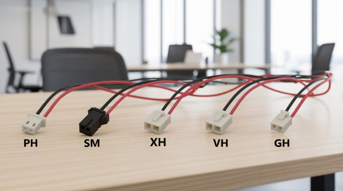
Comparison of Common Series Dimensions
When inspecting with the naked eye, pay attention to these details:
- SH / GH: Extremely narrow, suitable for high-density board-to-wire connections.
- PH: Features raised locking tabs on the sides; headers are typically through-hole or surface-mount.
- XH: Features a barbed latch on the top of the plastic housing; A latch may provide tactile or audible engagement when fully mated, depending on the exact connector design.
- SM: Features a tightly enclosed housing and typically comes in pairs (male-female connectors).
- VH: Large size with a sturdy latch, commonly found in high-current power inputs or control boards for large home appliances.
Terminology Tips
- Pitch: The distance between the centers of two adjacent terminals, measured in mm. This is the first value used to distinguish between series.
- Housing: A plastic casing that encloses the terminals, typically featuring a latch or anti-misinsertion mechanism.
- Header: The part soldered to the PCB, available in two forms: SMD (surface mount) and through-hole.
- Receptacle: The "female" part of a connector, usually referring to the end of the housing that contains the female terminals.
- Terminal: The internal metal conductive component that determines current-carrying capacity and the crimping process.
Once you understand these basic concepts, you won't be misled by "similar appearances" when identifying and selecting specific series. In the following sections, we'll break down the features, latch differences, and substitution considerations for each series in detail — but remember, the first step in identifying a JST connector is always to verify the series name, pitch, and housing structure simultaneously; none can be omitted.
● Why Is "JST" Not One Connector, but a Family of Series?
JST is both the brand name of a Japanese company (J.S.T. Mfg. Co., Ltd. / Japan Solderless Terminals) and a collective term for a vast family of connector series. Unlike USB-C, which has a single standardized interface definition, JST encompasses dozens of product lines---such as PH, XH, GH, SH, and VH---that differ completely in pitch, latching mechanisms, and housing structures. When engineers refer to "JST", they are usually just using it as a generic term out of habit.
Why does the industry refer to all kinds of small white connectors as "JST"?
This is similar to using a well-known brand name as a generic term for a product category, or using "Scotch" to refer to transparent adhesive tape---JST was extremely prevalent in small household appliances and industrial equipment during the 1980s and 1990s, especially the PH and XH series, which almost became synonymous with board-to-wire connectors. Later, many engineers would instinctively call any small, white connector with a latch a "JST". Over time, the specific series family names were overlooked, and only the "JST" brand label remained in common usage.
The True Determining Factor: Not "Looks", but the Series Family
To determine whether a connector is a genuine JST or to identify its specific model, one cannot rely solely on visual similarity; instead, one must verify its series family — that is, the letter codes such as PH, XH, and GH. For example:
- PH Series: 2.00 mm pitch, side-locking, widely used in battery management systems.
- XH Series: 2.50 mm pitch, top-mounted barbed latch, commonly found in power inverters.
- GH Series: 1.25 mm pitch, with a compact latch/contact structure, primarily used in servo motor encoders.
At first glance, all three series appear to be "small white plastic connector housings", but they differ in pitch, and the latch positions and shapes of the housings are also different; the terminal sizes are certainly not interchangeable. If you purchase them solely because they "look like JST", you are likely to end up with an incompatible model.
An even bigger pitfall: compatible parts, knockoffs, and "JST-like connectors."
The market is also flooded with JST-compatible, JST-style, or clone connectors, as well as JST-like connectors that are highly similar in appearance---such as certain "PH-compatible" series made by domestic manufacturers. Although the pitch and latch structure may be identical, the plastic material's temperature rating and the thickness of the terminal plating may differ. These JST-like connectors further amplify the risk of misidentification: if you have an original XH header but plug in a PH-style cable assembly, the consequences range from increased contact resistance or intermittent disconnections to board-level damage caused by overheating, short circuits, or polarity errors.
Misuse of Terminology vs. Correct Expression
| What you hear or want to say (misuse) | More Accurate Expression (Correct) |
|---|---|
| I need a JST PH series connector with a 2-position housing, 2.00 mm pitch, and matching PCB header and terminals. | I need a JST PH series connector with a 2.00 mm pitch and a 2-pin housing. |
| This board uses a 4-position XH series PCB header. | This board uses a 4-pin XH series header. |
| Verify the series, pitch, latch geometry, mating side, and terminal family before selecting a replacement. | You must verify the series, family, and pitch; otherwise, it won't fit or will have poor contact. |
Stop just saying "JST 2-pin"---it gives FAEs a headache
When communicating with suppliers or FAEs, simply saying "JST 2-pin" makes it impossible for them to determine whether you need PH, XH, SM, or ZH. The difference between 2.00 mm and 2.50 mm pitch is 0.50 mm---hard to distinguish with the naked eye---but the crimping tools and PCB pads are completely different. The correct way to ask is: "JST PH series, 2-position, 2.00 mm pitch, vertical PCB header, with matching housing and terminals". This saves time on back-and-forth confirmations and prevents non-returnable returns due to ordering the wrong part.
To sum it up: JST is not a single connector type, but rather an umbrella term for a family of connectors. Next time you encounter a small connector resembling a JST, you should first check the housing marking, then measure the pitch, and observe the latch geometry. Finally, confirm the latch geometry and mating side---only after completing these three steps can you truly determine which series family it belongs to, rather than being misled by its "JST-like appearance".
● What Are the Key Traits of the PH, XH, SH, GH, VH, and SM JST Series?
Simply put, the six series---PH, XH, SH, GH, VH, and SM---cover a pitch range from 1.00 mm to 3.96 mm, each catering to different current, density, and latch requirements. PH and XH are among the most common JST wire-to-board series, while SH/GH focus on miniaturization, VH handles high-current power connections, and SM is the workhorse for wire-to-wire applications. Their core differences center on three key factors: pitch, latch type, and whether they are wire-to-board or wire-to-wire.
Let's start by reviewing the big picture with a quick-reference table, and then we'll discuss how to identify them in practice.
Quick Reference Table for Six Common Series
| Series | Pitch | Locking Mechanism | Connection Method | Typical Applications |
|---|---|---|---|---|
| SH | 1.00 mm | No separate latch (held by terminal) | Wire-to-Board | UAV flight controllers, laptop interiors, micro-sensors |
| GH | 1.25 mm | Front friction lock | Wire-to-Board | Servo motor encoders, compact industrial connectors, and battery protection boards |
| ZH | 1.50 mm | Side-locking | Wire-to-Board | 3D printer heated beds, LED modules (Note: This series is also common and can be added) |
| PH | 2.00 mm | Side friction lock | Wire-to-Board / Rarely used: Wire-to-Wire | Small battery packs, BMS, and home appliance control boards |
| XH | 2.50 mm | Top barb lock | Wire-to-Board | Power supplies, inverters, 3D printers, general-purpose signal/power |
| SM | 2.50 mm | Enclosed male-female mating housing, top and bottom double latches | Wire-to-Wire | LED strip connectors, model batteries, and low-power motor harnesses |
| VH | 3.96 mm | Large-size heavy-duty latch | Wire-to-Board | Power input, large home appliances, and industrial power boards |
Note: Although ZH is not among the six most common types, it is indispensable in the standard series and is therefore included in the comparison.
What to look at first, what to look at next? --- The Three-Step Identification Method
When you get a connector that "looks like a JST", don't rush to check the datasheet. Follow this order:
- First, measure the pitch
- Next, check the connection type: wire-to-board or wire-to-wire?
- Finally, confirm the locking mechanism
The three most easily confused series (please pay special attention during procurement and maintenance)
- PH (2.00 mm) vs. ZH (1.50 mm)
- XH (2.50 mm) vs. SM (2.50 mm)
- GH (1.25 mm) vs. SH (1.00 mm)
In a nutshell: Remember these three key factors---pitch, latch, and connection method---and you'll never confuse PH, XH, SH, GH, VH, or SM again. Next time you get a sample, first measure the pitch, then check the housing for barbs or side protrusions, and finally confirm whether it connects to a PCB or has wires on both ends. Follow these three steps, and the series will become clear.
How Do You Identify a JST Connector Instead of Just Guessing "It Looks Like 1.25 mm"?
To accurately identify a JST connector, you need to examine at least four key factors: pitch (spacing), number of positions/circuits, housing and latch geometry, and mounting method. Relying solely on dimensions is far from sufficient, as there are numerous non-JST connectors on the market with similar appearances (such as Molex PicoBlade and non-JST micro connector families / JST-like alternatives) that can lead you to mistakenly believe they are "JST-like 1.25 mm connectors". The correct approach is to establish an identification workflow, starting with measurements and proceeding through a process of elimination.
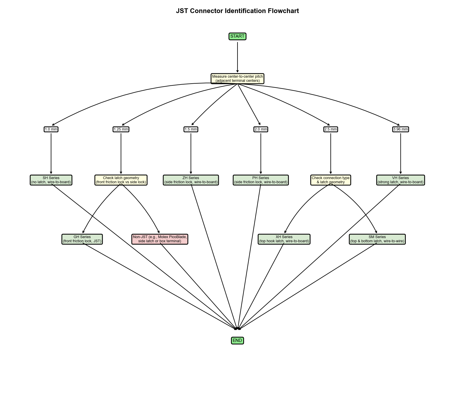
First, use a caliper to measure the center-to-center distance between adjacent terminals: 1.00 mm → SH, 1.25 mm → GH or non-JST PicoBlade, 1.50 mm → ZH, 2.00 mm → PH, 2.50 mm → XH or SM, 3.96 mm → VH.Next, examine the mating side: if the harness end has a square hole for inserting into a PCB socket, it is wire-to-board (PH/XH/SH/GH/VH); if it is designed to mate with another harness, it is wire-to-wire (primarily SM). Third, check the locking mechanism: no locking mechanism indicates SH; a side friction strip indicates PH/ZH; a top barb indicates XH; a front protrusion indicates GH; and dual top-and-bottom latches indicate SM. Finally, confirm the type by combining the markings (manufacturers often include series names) and the device type (SH/GH are commonly used for drone flight controllers, XH/VH for power boards, and SM for LED strips). By following these four steps, you can avoid misidentification based solely on appearance.
Why is the "1.25 mm" size particularly prone to misidentification?
Because there are numerous small connectors with a 1.25 mm pitch on the market. In addition to JST's GH series, there are Molex PicoBlade, HRS (Hirose) DF13, and numerous unbranded domestic micro connectors. Their latch mechanisms and terminal structures are completely different:
- The GH's friction latch is located on the front of the mating side and appears as a small protrusion.
- PicoBlade uses a different latch/contact geometry from JST GH, and the terminals feature a "box-shaped" crimp design.
If you purchase based solely on the "1.25 mm" pitch, you are likely to end up with incompatible components. Therefore, pitch measurement is only the first step; you must also consider the lock style and mating side to confirm the correct series.
Identification Reference Table (Quick Match by Pitch and Locking Mechanism)
The table below helps you quickly identify candidate series based on your measurement results. When using it, first check the pitch, then cross-reference the lock style and connection type.
| Measured Pitch | Candidate Series | Lock Style | Connection Type | Examples of Typical Devices |
|---|---|---|---|---|
| 1.00 mm | SH | No separate latch (terminal friction) | Wire-to-Board | Drone flight controllers, micro cameras |
| 1.25 mm | GH | Front friction latch | Wire-to-Board | Servo motor encoders, battery protection boards |
| 1.50 mm | ZH | Side friction latch | Wire-to-Board | 3D printer hot beds, LED modules |
| 2.00 mm | PH | Side friction latch | Wire-to-Board | Small BMS, home appliance control boards |
| 2.50 mm | XH | Top barb | Wire-to-Board | Power inverters, 3D printer power supplies |
| 2.50 mm | SM | Top and bottom double latches (enclosed housing) | Wire-to-Wire | LED strip plug-in, model batteries |
| 3.96 mm | VH | Large-size heavy-duty latch | Wire-to-Board | Power input, industrial power board |
Note: Although both are 2.50 mm, the lock style and mating side of XH and SM are completely different; they must never be interchanged.
List of Common Misidentifications ("I thought it was JST XX, but it wasn't")
- Misidentification 1: 1.25 mm must be GH.
- Misidentification 2: A 2.00 mm connector with a protrusion on the side is PH.
- Misidentification 3: White, small, and with a latch = JST.
In a nutshell: Next time, don't place an order just because it "feels like 1.25 mm". Grab a caliper to measure the pitch, then follow the identification workflow to determine the connector type, lock style, and mating side in sequence. Finally, compare it to typical applications---you'll find that the genuine JST series actually has very distinct features, while those "look-alike" JST-like connectors/clone connectors/compatible alternatives can be quickly ruled out.
● When Identifying a JST Connector, What Should You Measure First and Check Next?
When identifying a JST connector, the first step is always to measure the center-to-center pitch---that is, the distance between the centers of two adjacent terminals---rather than measuring the total width of the housing or simply guessing "it's probably 2.0". The second step is to check the pin count and whether it is single-row or dual-row. The third step is to inspect the latch geometry — where the latch is located, whether it's on the side or the front, and whether there are separate latches. Finally, cross-verify by considering the device type (e.g., drones, battery packs, 3D printers). By following these four steps in order, many common misidentifications can be avoided.
Four-Step Identification Process
Step 1: Measure the center-to-center pitch
- Use a digital caliper to measure the distance from the center of the first pin to the center of the second pin. If a caliper is unavailable, measure the total distance from the first pin to the Nth pin, then divide by (N-1).
- Common mistake: Measuring the outer edges at both ends of the housing and dividing by the number of pins—this includes the housing wall thickness, so 1.00 mm might be measured as 1.30 mm, leading to a false positive.
- After following the correct procedure, you will obtain the following value correspondences: 1.0 → SH; 1.25 → GH (note that this could also be PicoBlade); 1.50 → ZH; 2.00 → PH; 2.50 → XH or SM; 3.96 → VH.
Step 2: Confirm the pin count and number of rows
- Count the number of positions/circuits, and verify whether the connector is single-row or dual-row. The available position range varies by series and should be checked against the manufacturer datasheet, but the pin count ranges vary by series (e.g., SH typically ranges from 2-20, while VH typically ranges from 2-12).
- Also check whether it is single-row or dual-row—dual-row is typically used for higher density. For example, the PH series has dual-row versions, while the XH series is generally single-row only.
Step 3: Examine the latch geometry
This is the easiest step to overlook, yet it is the most critical. Turn the housing over to view the front, side, and mating side to examine the “appearance” of the latches:
- No separate latch: SH series usually has no separate external latch and relies mainly on contact retention; it may not produce an audible latch click.
- Side friction strips: PH and ZH series; the housing has raised, strip-like protrusions on the sides.
- Top barb: XH series—features a downward-curved hook on top that engages the pin header's opening upon insertion.
- Front protrusion: GH series, featuring a short protrusion on the front of the mating side.
- Enclosed wire-to-wire housing with latch features: SM Series; sealing or IP rating depends on the specific variant—features latches at both the top and bottom when the male and female connectors are mated, and the housing is nearly fully enclosed.
Step 4: Cross-verify based on equipment type
Typical applications for different series are highly concentrated, which can serve as a cross-check:
- Drone flight controllers / micro cameras → Most likely SH (1.00 mm) or GH (1.25 mm)
- Battery management systems (BMS) / small appliances → PH (2.00 mm)
- 3D printer power supplies / inverters → XH (2.50 mm)
- LED strip connectors / model battery extension cables → SM (2.50 mm wire-to-wire)
- Power input boards / large appliances → VH (3.96 mm)
Decision Flowchart
Incorrect vs. Correct Examples (Real-world repair/purchasing scenarios)
| Common Misconceptions | Why It's Wrong | Correct Approach / Explanation |
|---|---|---|
| I measured the total width of the housing at 5 mm, and there are 2 holes, so the pitch is 2.50 mm | The housing wall thickness accounts for about 0.8 mm, so the actual pitch is only 2.00 mm (PH series) | Measure the center-to-center distance between two adjacent terminals, not the ends of the housing. |
| This may be a 1.25 mm connector, but the series must be verified by pitch, latch geometry, mating side, and markings. | The 1.25 mm pitch is available in GH, as well as non-JST variants like PicoBlade and DF13, which have completely different latch mechanisms | First, measure the pitch, then check the latch geometry---GH has a protrusion on the front, while PicoBlade has a latch on the side. |
| A 2.50 mm pitch alone is insufficient; verify the series, housing, latch, terminal family, and mating part number. | There is also the 2.50 mm SM series, which is typically wire-to-wire; its housing and latch are incompatible with XH, and interchanging them will damage the terminals. | Confirm whether it's wire-to-board (XH) or wire-to-wire (SM), then purchase the corresponding cable or header. |
| The caliper reading is 2.48 mm, which is roughly 2.50 mm, so it should be fine. | If the caliper is not pressed evenly or the measurement point is not aligned with the center of the terminal, this may cause measurement errors. | Keep the caliper perpendicular to the pin axis, measure two adjacent pin pairs, and take the average. |
Additional Reminders Regarding Measurement Errors
- Perspective distortion in photos: When photographing connectors with a smartphone, the wide-angle lens can make the pitch at the edges appear larger than in the center, so never use photos to measure pitch.
- Mistaking the outer edge of the plastic housing for the center: Some housings have reinforcing ribs between the terminals, and beginners often mistakenly include the width of these ribs in the pitch measurement. Remember: Measure only the center points of the metal terminals.
- Caliper misalignment: If the caliper is not perpendicular to the connector's surface, the reading will be too small. The correct method is to place the connector flat and press the caliper's jaws vertically into the center indentations of two adjacent terminals.
Practical Advice: Next time you come across an unknown JST connector, don't take a photo and post it on social media asking, What model is this ?---instead, use a caliper to measure the center-to-center pitch, count the pin count, and examine the latch geometry. After completing these three steps, you'll be able to identify it yourself. A distributor selection tool can be used to filter by pitch, number of positions, latch type, and mounting style to verify your assessment.
● Which Connectors Are Commonly Mistaken for JST, and How Do You Rule Them Out?
The connectors most easily mistaken for JST are typically those with "small white plastic connector housings" and a pitch between 1.00--2.50 mm, especially Molex PicoBlade (1.25 mm), HY 2.00 (2.00 mm), and numerous unbranded domestic 1.25 mm / 2.00 mm micro connectors. The core reason for misidentification is focusing solely on appearance, color, and pitch while overlooking the latch mechanism, terminal family, and mating compatibility. The method for ruling them out is simple: first confirm the product series, then check whether the mating side matches, and finally verify that the terminal series is consistent — completing these three steps will weed out the vast majority of "JST-like / JST-compatible / clone connectors".
Common JST-Like or JST-Compatible Connectors to Verify Carefully
The table below lists the most common confusing connectors you're likely to encounter and accidentally purchase. Remember: the same pitch does not mean they are interchangeable, especially in a market flooded with clone connectors.
| Often Mistaken For | What It Actually Is | Key Differences (How to Distinguish) |
|---|---|---|
| JST GH (1.25 mm) | Molex PicoBlade | Different latch positions: The GH's positive latch is on the front of the mating side (small protrusion); the PicoBlade's latch is on the side, and the terminals are box-shaped crimped contacts. |
| JST PH (2.00 mm) | HY 2.00 (Common in China) | Different terminal geometries: The PH terminal features an open "U"-shaped crimping area; the HY 2.0 terminal is wider, and the anti-misinsertion ribs inside the housing are positioned differently. Forcing them to interconnect will damage mating compatibility. |
| JST XH (2.50 mm) | Domestic XH-compatible | The original XH connector features a top-mounted positive latch with a distinct clicking sound; many clone connectors have latches with incorrect angles or made of softer materials, resulting in a loose feel during insertion and removal, and their temperature rating is typically one grade lower. |
| JST SM (2.50 mm) | Molex or TE 2.50 mm wire-to-wire | The SM housing features a double-latch, sealed design; similar products from other brands may have a single-sided latch or a completely different housing structure. You must check the profile of the mating side. |
| Any 1.00 mm white plastic housing | JST SH or unbranded domestic micro | The SH does not have a separate latch and relies entirely on the elasticity of the terminals; many counterfeits add a fake latch for "feel," which actually prevents them from fitting into the original socket. |
Never rely solely on these characteristics to make a judgment
Based on years of field support and post-sales failure analysis, the vast majority of JST misidentifications stem from the habit of ordering at a glance. Engineers and procurement staff are often drawn to superficial features like pitch, color, and pin count, yet overlook the underlying parameters that truly determine usability---such as latch structure, terminal family, and mating compatibility. The five don'ts listed below cover nearly 90% of common pitfalls---please review each point to avoid repeating these mistakes.
- Measuring pitch alone: A 2.50 mm pitch could be XH or SM, and the two are incompatible.
- Relying solely on color: White plastic housings are not exclusive to JST; Molex, TE, HRS, and even unbranded manufacturers produce white ones.
- Counting pins only: A 2-pin PH and a 2-pin HY 2.0 look very similar, but their terminal retention force and current-carrying capacity differ significantly.
- Relying solely on "forcing it in": Many clone connectors are intentionally designed to fit into original manufacturer sockets, but the positive latch cannot fully engage, or the terminal contact surfaces are misaligned, leading to intermittent power loss.
Remember this golden rule: Mating compatibility is not about "whether it can be forced in", but rather "whether the latch is fully engaged, whether the terminals are of the same type, and whether the retention force meets standards". A clone may plug in, but it will quickly reveal issues under vibration or thermal cycling conditions.
Elimination Method: Three Steps to Identify a Genuine JST
If you have an unidentified connector, or if your bill of materials simply lists "JST 2.0 4-pin", follow this sequence to eliminate potential sources of confusion:
- First, check the series marking
Some original manufacturer housings may feature series markings or mold marks, but the presence of engravings (such as “PH,” “XH,” or “GH”) should not be the sole basis for judgment. No engravings → It may be a clone connector or another brand, requiring further verification.
- Next, examine the positive latch structure on the mating side
• GH: Front protrusion
• PH: Side friction strip
• XH: Top-mounted barb
• SM: Dual top and bottom latches
If the latch shape does not match the standard definition for this series, do not attempt to interlock.
- Finally, verify the terminal family
Even if the housing shape is an exact replica, the terminal model may differ. For example, the original PH terminal uses SPH-002T-P0.5, while the imitation may use a thinner substitute terminal, resulting in insufficient pull-out force after crimping. When purchasing, request that the supplier provide the terminal part number, compatible wire gauge, material/plating information, and crimping specifications; for critical applications, also verify pull-out force, insertion/withdrawal force, temperature rise, and mating compatibility.
Pre-Purchase Checklist
Before requesting a quote or placing an order with a supplier, stop and think — don't just copy and paste the part number. Many procurement disputes stem not from suppliers shipping the wrong items, but from omissions of critical requirements in the request for quotation. The checklist below includes six parameters that are most easily overlooked but must be verified — especially the "original terminal part number" and "whether original JST is required" —which can directly filter out over 80% of incompatible materials. Please check each item before sending.
- Series Name: PH / XH / GH / SH / SM / VH, etc. Do not simply write "JST".
- Pitch: Must match the series name (e.g., PH must be 2.00 mm).
- Latch type: Side friction / Top barb / Front tab / Top and bottom dual latches.
- Connection Type: wire-to-board or wire-to-wire.
- Original manufacturer's part number (if available): e.g., SPH-002T-P0.5 corresponds to the PH series.
- Requirement for genuine JST: If clone connectors are acceptable, interchangeability test standards must be clearly defined (e.g., insertion/withdrawal force, temperature rise, vibration).
In a nutshell: Don't be fooled by a "small white plastic housing". The true way to determine if a connector is a JST---and whether it's compatible with your board---relies on the positive latch structure, terminal family, and series markings, not a caliper or the naked eye. Next time you encounter a suspicious "JST", pull out this checklist and go through it item by item---you'll be surprised to find that many"look-alikes" aren't in the same league.
Where Are Different JST Series Used, and How Do You Identify Them in 3D Printers, Fans, Keyboards, and Drones?
To determine which JST series is used in a specific device, you can't rely solely on the device name (such as Ender 5 Plus or SKR Mini). You must examine the physical characteristics of the board header: first measure the pitch, then count the number of pins, and finally determine whether the line serves a signal/power path or a specific function, such as a fan, battery, or motor. Different functions correspond to different series---for example, on 3D printer motherboards, fan connectors commonly use PH or XH, limit switches often use PH, while thermistors may use the smaller ZH. Below, we'll first establish a general application mapping, then provide identification steps for three typical devices.
Mapping Table: Application Scenarios to Common JST Series
In actual repair or selection scenarios, it's impossible to remember which connectors are used for every brand and model. A more efficient approach is to develop a "function → series" mapping mindset: How much current does a fan require? Is a limit switch a signal or power connection? What is the typical pin pitch for a thermistor? The table below summarizes the most common correspondences from a functional perspective. When using it, please cross-verify with your own measurements of the board-side sockets; do not simply apply device names directly.
| Application Scenario / Function | Typical Series | Pitch | Connection Method | Description |
|---|---|---|---|---|
| 3D Printers: 4020/5015 Fan | PH (2.00 mm) or XH (2.50 mm) | 2.00 / 2.50 | Wire-to-Board | Depends on the motherboard design; older models often use XH, while newer compact boards often use PH |
| 3D Printers: Limit Switches (Mechanical/Photoelectric) | PH (2.00 mm) is the most common | 2.00 | Wire-to-Board | A few use XH; ZH is rarely used |
| 3D Printers: Thermistors | ZH (1.50 mm) or PH | 1.50 / 2.00 | Wire-to-Board | ZH is commonly used for small boards, while PH is used for large boards |
| 3D Printer: Stepper Motor (4-pin) | PH (2.00 mm) or XH | 2.00 / 2.50 | Wire-to-Board | Most 42-step stepper motors use PH |
| Drone flight controller / ESC signals | SH (1.00 mm) or GH (1.25 mm) | 1.00 / 1.25 | Wire-to-Board | High density, high vibration resistance required; GH latches are more reliable |
| Drone Battery Balancer | PH (2.00 mm) | 2.00 | Wire-to-Board | Common for small 2--4 cell batteries |
| Internal keyboard flex Cables / LED strips | PH (2.00 mm) or SM (2.50 mm) | 2.00 / 2.50 | Wire-to-Wire or Board | SM is commonly used for light strip Connectors, while PH is used for key-to-board connectors |
| Home Fan Control Board | VH (3.96 mm) or XH | 3.96 / 2.50 | Wire-to-Board | VH for power input, XH for control signals |
| General consumer electronics batteries (small) | PH (2.00 mm) | 2.00 | Wire-to-Board | Excluding Bluetooth headsets and small toys (which use the smaller SH) |
Four-Step Method for Device-Side Identification
When you have a specific device (such as a 3D printer, drone, or keyboard) and need to determine the connector series, don't search for "What JST does such-and-such device use"? Instead, follow these steps to verify on-site:
- Locate the board header
Locate the corresponding socket on the PCB and check whether it is a through-hole or surface-mount type, and look for any silkscreen markings nearby (sometimes labeled “FAN”, “ENDSTOP” or “BAT”).
- Measure the pitch and number of positions / circuits
Use a caliper to measure the center-to-center distance between two adjacent metal pins. Also, count whether it has 2 pins, 3 pins, or more.
- Analyze the signal/power path
• If it has two pins and is connected to a fan or heating element → It is likely a power path, with slightly higher current, commonly labeled XH or VH.
• If there are three pins (e.g., limit switch or thermistor) → Most likely a signal path, commonly labeled PH or ZH, as the current is very low.
• If it is a multi-pin ribbon cable (5-10 pins) → It is usually a signal bus, possibly using GH, SH, or a dual-row PH.
- Use the mapping table above to narrow down the options
Identify 1-2 candidate series based on function, then use the locking mechanism type (side friction, top barb, front tab, etc.) to make the final confirmation.
Case Studies for Three Typical Device Categories
Below, I've selected three device categories where pitfalls are most common---3D printers, drones, and keyboards---to demonstrate how to practically apply the four-step method (measure spacing, identify function, check mapping, verify latch) in each case. Each example lists the series used for common internal functions and highlights the often-overlooked fact that "multiple series coexist within the same device". You can directly compare these with your own device to troubleshoot.
Case 1: 3D Printers (Ender 3 / SKR Mini / Octopus, etc.)
• Fan connectors: Measure pitch—2.00 mm → PH series; 2.50 mm → XH series.
• Limit switches: Almost all use 2.00 mm PH (3-pin, with only two pins used).
• Thermistors: Many small boards (such as the SKR Pico) use 1.50 mm ZH; older models use 2.00 mm PH.
• Motor connectors: PH is common for standard 42-step stepper motors, but the motherboard may use XH.
On the same SKR Mini E3 board, you'll find PH (for fans and limit switches), ZH (for thermistors), and XH (for power input) all coexisting—which is perfectly normal.
Case 2: Drones / Flight Controllers (F4 / F7 / Pixhawk)
• GPS / Data Link Interface: 1.25 mm GH is becoming increasingly common because it features a front latch, offering better vibration resistance than SH.
• Battery voltage detection port: 2.00 mm PH.
• LED strip connectors: Sometimes 2.50 mm SM (wire-to-wire).
Case 3: Keyboards (Ducky / DIY Custom)
• Key-to-board connectors to the main controller: Commonly 2.00 mm PH (5-pin or 4-pin).
• RGB LED strip daisy-chain cable: 2.50 mm SM (male-to-female connector, with wires on both ends).
• Battery connector (wireless keyboard): 2.00 mm PH or smaller ZH.
It is normal for multiple connector types to coexist within a single device, not an anomaly
Many beginners are surprised when they first disassemble a device: Why is the fan a PH, the limit switch a PH, but the thermistor a ZH?---This is because different functions have varying requirements for current, size, and latch reliability. Never assume that an entire device uses only one JST series. The correct approach is to perform device-side identification for each individual connector, rather than applying a single series name to the entire device.
Practical advice: Next time you encounter an unfamiliar connector on a 3D printer, drone, or keyboard, don't rush to post asking, "What kind of JST is this"? Take out a caliper to measure the pitch, check what function it's connected to (fan/limit switch/battery/signal), and then look for the intersection in the mapping table above---you'll find that 80% of the answers lie within these four steps. Unikeyic's selection tool also supports filtering by pitch, pin count, and application scenarios; feel free to use it to verify your judgment.
● How Are JST Series Commonly Used on 3D Printers, Fans, and Control Boards?
On 3D printers, fans, and controller boards, the distribution of JST series depends primarily on the motherboard generation and functional modules, rather than the device brand. Common series include XH (2.50 mm), PH (2.00 mm), ZH (1.50 mm), and, in rare cases, GH / SH (1.25 / 1.00 mm). Fan connectors are typically XH or PH, while signal interfaces for sensors, displays, and serial ports often favor the smaller-pitch ZH or GH. For a broader view of board-level interfaces beyond the JST series, see this guide to motherboard connector types. The most critical point: do not assume that a white 2-pin plug is a JST PH---you must measure the actual spacing and latch structure of the board header.
Below, we'll first look at a common interface identification chart for controller boards, then a pre-fan-replacement checklist, and finally a reusable workflow example.
Controller Board Interface Identification Chart
When faced with an unfamiliar controller board, many engineers instinctively ask, "What connectors does this board use?" In fact, a more efficient approach is to do the opposite: first identify what function the interface connects to---fan, motor, thermistor, or display? Then, based on the typical current and signal requirements for that function, work backward to determine the possible connector series. The table below provides a quick reference based on "function". Please note when using this table: the same function may correspond to different connector series across different board generations; be sure to verify your findings by combining them with your own measurements of the board header.
| Interface Function | Common Pitch | Typical Series | Locking Features | Notes |
|---|---|---|---|---|
| 12V/24V Fan (4020/5015) | 2.50 mm or 2.00 mm | XH or PH | Top Latch (XH) / Side Friction (PH) | Newer compact boards tend to use PH, while older models mostly use XH |
| Limit Switch (Mechanical/Photoelectric) | 2.00 mm | PH | Side friction | Almost universally standardized to PH, with very few exceptions |
| Thermistors | 1.50 mm or 2.00 mm | ZH or PH | Side friction (ZH is narrower) | ZH for small boards, PH for large boards |
| Stepper motor (4-pin) | 2.00 mm or 2.50 mm | PH or XH | Side friction / Top barb | Mostly PH on the motor side, both types on the mainboard side |
| Display / LCD ribbon cable | 1.25 mm or 1.00 mm | GH or SH | Front tab (GH) / No latch (SH) | High-density signal interface |
| UART / Serial Port Debugging | 1.25 mm | GH | Front friction latch | Select GH for high vibration resistance |
| Power Input (VIN) | 3.96 mm or 2.50 mm | VH or XH | High-strength latch (VH) / Top barb (XH) | Use VH for high current |
Checklist Before Replacing the Fan
The fan connector is by far the most commonly mispurchased part for 3D printers and control boards. The reason is simple: both are white 2-pin sockets, but one might be PH while the other is XH. The pin spacing differs by just 0.5 mm, but plugging them into the wrong socket will immediately damage the terminals. Many users see "universal 2-pin fan" online and place an order, only to discover upon arrival that the connectors don't align. The checklist below outlines the details you must verify before replacing a fan — please check each item off before placing your order.
- Measure the board header pitch: 2.00 mm or 2.50 mm? A difference of just 0.50 mm makes them incompatible.
- Confirm the latch type: top-mounted hook (XH) or side friction strip (PH)? The two are incompatible.
- Confirm voltage and current: 12 V or 24 V? The signal/power path of the fan connector determines whether you can replace it directly.
- Check the motherboard silkscreen: Some control boards are labeled "FAN1" or "FAN2", and sometimes include the series designation (e.g., "PH2.0").
- Do not trust "universal 2-pin fans": Many sellers lump PH and XH together; you must verify the board header yourself.
Step-by-Step Guide: From "No Idea" to "Identifying the Series"
Below is a real-world example of replacing a 3D printer hotend fan, demonstrating the entire process from "seeing the connector on the board" to "determining whether it's PH or XH". This process doesn't require you to memorize any brand or model numbers---all you need is a caliper and an eye for identifying connectors. You can use these steps as a template for any control board or connector you have on hand.
- Locate the board header: Find the socket labeled "HE_FAN" or "Hotend Fan" on the main board.
- Measure the pitch: Use a caliper to measure the center-to-center distance between two adjacent pins; the result is 2.00 mm.
- Check the latch: The side of the connector has a raised friction strip, with no upward-facing hook at the top.
- Functionality: The fan draws moderate current (approx. 0.1--0.3 A), so the PH series is sufficient.
- Conclusion: This is a JST PH series connector, 2.00 mm, 2-pin.
- Procurement: Look for PH series connectors with wire terminals or pre-made fan harnesses; do not purchase XH.
If the measurement result is 2.50 mm and there is a top barb → that is the XH series. On the same control board, different fan connectors may mix PH and XH (e.g., some boards use PH for hot-end fans and XH for component fans), so the above process must be performed separately for each connector.
Important Note: Do not rely on "device brand" instead of "actual board header measurement."
People often claim online that "Ender 3 fans use XH", but different batches or generations of Ender 3 models may have switched to PH. The only truly reliable indicator is the board header on the controller board right in front of you. Similarly, the connector series may vary completely between different models of brands like Octopus, SKR, and Flsun. Getting into the habit of measuring and observing the latch shape is far more reliable than memorizing "general rules" for a specific model.
Practical Tip: The next time you upgrade your 3D printer's fan or repair the controller board, first use a caliper to measure the spacing of the board header, then examine the latch shape, and finally cross-reference it with the identification chart above---you'll find that XH, PH, and ZH are actually very easy to distinguish, and it's quite normal to find two or three different series on the same board. Unikeyic's selection tool supports filtering by pitch, latch type, and application scenario — feel free to use it to verify your identification results.
● Which JST Types Are Most Common in Keyboards, Battery Leads, LED Wiring, and Drones?
In keyboards, battery leads, LED strips, and drone equipment, the most common JST types are: PH (2.00 mm) and SH (1.00 mm), which are commonly found in internal batteries, daughterboards, or control board connections within some keyboards; SM (2.50 mm) is used for inline wire pairs in LED strips and battery leads; GH (1.25 mm) and SH (1.00 mm) serve as the primary signal connectors on drone flight controllers; meanwhile, PH (2.00 mm) is widely used in small battery interfaces and auxiliary modules. However, different series may be mixed within the same device type. For example, battery leads in low-power devices are often PH, but if the current is slightly higher, they may switch to XH or even non-JST solutions. Below, we'll first examine the distribution using an application mapping table, then provide a template for disassembly identification records, and end with a reminder: Don't blindly trust forum screenshots.
JST Series Mapping Table for Common Devices
This table summarizes the most frequently encountered series from a "device + function" perspective. Please keep in mind when using it: different interfaces on the same device may belong to different series, so each must be measured and evaluated individually.
| Device / Function | Common JST Series | Pitch | Connection Method | Typical Applications |
|---|---|---|---|---|
| Keyboard: Internal battery connector | PH or SH | 2.00 mm or 1.00 mm | Wire-to-Board | Wireless keyboards, custom PCB battery leads |
| Keyboard: Daughterboard / Key-to-board separator | PH | 2.00 mm | Wire-to-Board | Flex cable from Ducky and DIY keyboard controllers to Type-C daughter boards |
| Battery lead (low current), XH (medium current) | PH (low current), XH (medium current) | 2.00 / 2.50 mm | Wire-to-Board | RC model batteries, 3D printer heated bed power supply |
| LED strip connector | SM | 2.50 mm | Wire-to-Wire (inline wire pair) | Commonly used for LED strip lights, low-power wire-to-wire connections, and some low-power module harnesses; battery leads must be selected based on current, wire gauge, and device type---conclusions cannot be drawn solely based on "JST" or "2-pin". |
| Drone flight controller: ESC signal | SH or GH | 1.00 / 1.25 mm | Wire-to-Board | F4/F7 Control signals from the flight controller to the ESC |
| Drone: GPS / Data Link Interface | GH | 1.25 mm | Wire-to-Board | With a positive latch, better retention than SH in many vibration-prone applications |
| Drone: Battery Voltage Detection Port | PH | 2.00 mm | Wire-to-Board | Small 2S--4S battery balancing cable or voltage sensing interface |
| General LED drivers / low-power light boards | PH or XH | 2.00 / 2.50 mm | Wire-to-Board | Connection between the constant-current driver board and the LED board |
Disassembly Identification Record Template
Before every repair or upgrade, make it a habit to "record first, then proceed". Below is a template you can copy directly into a memo or notebook:
【Device Name】: _________________
【Connector Location】: _________________ (e.g., "Keyboard Main Board Battery Socket")
【Function Description】: _________________ (Battery / Signal / LED Strip Connector)
【Measured Pitch】:_________________ mm (center-to-center distance between adjacent pins)
【Number of Pins】: _________________
【Locking Mechanism】: □ Side friction strip □ Top barb □ Front tab □ Top and bottom dual latches □ No locking mechanism
【Connection Type】: □ Wire-to-Board (PCB insertion) □ Wire-to-Wire
【Board-Side Connector Photo】: □ Taken (recommended to include a caliper in the frame)
【Series Code】: _________________ (e.g., PH / XH / SM / GH)
【Remarks】: _________________
Take at least two photos each time you disassemble the unit: one showing the overall connector location, and one close-up of the pitch measured with a caliper. This prevents you from having to repeatedly disassemble and reassemble the unit or place orders based on memory.
Do not place orders based solely on forum screenshots (especially for popular topics like Ducky keyboards or RC model battery leads / low-power model wiring).
People often claim online that "Ducky keyboards use JST PH 2.0 2-pin connectors," but different batches and models (e.g., One 2 Mini vs. One 3 SF) can be completely different — some use SH, and others even use non-JST Molex PicoBlade connectors. Similarly, drone battery leads may be XH or SM, not PH. No amount of "online references" can replace the actual physical component in your hands. The correct approach is to disassemble the device, use the provided template to record your own measurements, and then proceed with the purchase.
Practical Summary: For keyboard battery leads, check the pitch first (1.00 mm → SH, 2.00 mm → PH); for LED strip connectors, check if they're wire-to-wire---if so, suspect SM first; for drone flight controller signal interfaces, measure the spacing first---1.00 mm calls for SH, 1.25 mm calls for GH, and confirm the front latch. Finally, always trust your calipers and photos, not the "general rules" on forums.
How Should You Crimp, Replace, and Source JST Connectors Without Buying or Installing the Wrong Parts?
When purchasing JST connectors, do not simply describe them as "2-pin white plugs". You must verify at least six pieces of information: series, housing, header, terminal, wire gauge, and mating side. Many hobbyists like to buy "kits containing various JST types", but such kits are only suitable for desktop experiments, not for formal repairs or mass-production replacements---because terminals from different series vary significantly in crimp height and retention force, and mixing terminals from a kit can easily lead to poor contact or pin disengagement. Below, we will provide, in order, a sourcing checklist, a decision table for replacement decisions, a crimping step-by-step guide, and a section of common troubleshooting FAQs. Each step directly addresses potential pitfalls you might encounter in your actual work.
Procurement / RFQ Form: Please fill out these nine items before sending to suppliers
Don't just send a blurry photo of the actual product or write "JST 2-pin harness". The checklist below ensures you ask the right questions the first time, and suppliers can quote the correct parts. We recommend copying it into your email or RFQ.
| Parameter Items | What to Include | Example |
|---|---|---|
| Series | ______ | PH / XH / GH / SH / SM / VH |
| Pitch | ______ mm | 2.00 mm |
| Number of positions | ______ | 2 / 3 / 4 / ... |
| Male/female side | □ housing (with leads) □ header (solder tab) | housing |
| Header orientation | □ Vertical □ Right-angle □ SMD | Vertical |
| Wire Gauge (AWG) | ______ AWG | 24 AWG |
| Rated current | ______ A | 2 A |
| Application | Battery leads / Fans / Signals / Power | 3D printer fan |
| Do you need OEM JST? | □ Original □ Compatible (specify test standards) | Original |
Note: For bulk purchases, be sure to request the original terminal model number (e.g., SPH-002T-P0.5 from the PH series), as many imitation terminals have insufficient material thickness and elasticity, which can result in substandard pull-out strength after crimping.
Replacement Decision Chart: Replace only the plastic housing, only the terminals, or the entire assembly?
In practice, when a connector is damaged, it is not always necessary to replace the entire unit. The table below helps you quickly determine the minimum replacement scope based on the fault symptoms, saving you both time and money.
| Fault Symptom | Recommended Action | Description |
|---|---|---|
| Housing latch broken, but terminals intact | Replace only the housing (remove terminals and reinsert them into the new housing) | Requires a pin removal tool, and the housing must be a perfect match within the same series |
| Terminal oxidation, broken wires at crimping points, and increased contact resistance | Replace only the terminal (re-crimp the same terminal model) | Must use the correct crimping tool and the same terminal model |
| Board-side header pins are bent, corroded, or have melted plastic | Replace only the header (desolder and install a new one) | Pay attention to the pin length and the positioning of the pin dimensions of the header |
| The locking mechanism fails after repeated insertion/removal, or the terminal retention force significantly decreases | Replace the entire wiring harness (including housing, terminals, and wires) | The most efficient solution during repair is to prevent secondary failures |
| The original cable has damaged insulation, broken inner conductors, or is the wrong length | Replace the entire cable assembly (including housing, terminals, and wires) | Suitable for applications requiring high vibration resistance or high flex life |
The core principle of replacement decision-making is: do not discard the entire cable just because the rubber housing is damaged, nor replace the entire board-to-cable connector just because a single terminal is oxidized. Conversely, if the wire itself has aged, replacing only the terminals without replacing the wire constitutes an ineffective repair.
Crimping and Assembly Checklist (Particularly Strict for Fine-Pitch Series)
JST's micro series (SH, GH, PH, etc.) are extremely sensitive to crimping quality. A non-standard crimp can prevent the terminal from locking properly into the housing or cause the pins to pop out during use. Please strictly follow the sequence below.
- Choosing the Right Crimping Tool
• Hobbyist/Small-Batch: Use adjustable crimping pliers such as the IWISS or Engineer PA-09, and refer to the crimping height specified for the terminals in the datasheet (for example, PH terminals require a crimp width of 0.8-0.9 mm).
• Mass production: Use manufacturer-recommended dies and semi-automatic or fully automatic crimping machines.
• Never crimp directly with needle-nose pliers or standard electrician's pliers—this will deform the terminals and result in an improper crimp.
- Wire Stripping Length Must Match Wire Gauge
• Refer to the datasheet for the terminal's applicable wire gauge (e.g., PH terminals are suitable for 24-28 AWG).
• The stripping length is typically 2.00-2.50 mm (varies slightly by series); the exposed conductor length must exactly match the terminal's crimping zone—it must not be too long or too short.
- Crimping sequence: crimp the conductor first, then the insulation
• Place the terminal in the corresponding slot of the crimping tool (separating the conductor area from the insulation area).
• First, crimp the conductor area (to ensure a reliable electrical connection).
• Second, crimp the insulation area (to secure the insulation and prevent the conductor from being stressed when pulled).
• Post-crimping inspection: The conductor must not protrude too far beyond the front of the terminal; the insulation must not be crimped into the conductor zone; the flared end of the terminal must be visible.
- Insert the terminal into the housing
• Confirm orientation: The terminal's spring tabs (barbs) should face the latch side of the housing.
• Insert from the rear of the housing (wiring side); it is in place when you hear a “click” or feel the spring-loaded tabs engage in the slots.
• Gently pull the cable to verify: The terminal should not be pulled out.
- Finally, perform a mating test
• Connect to the corresponding pin header or mating housing to check that the latch is engaged and that electrical continuity is normal.
Troubleshooting FAQ
Below are the four most common on-site issues, each with its direct cause and solution.
Q1: What should I do if the terminal won't fit into the housing after crimping?
- Possible causes: The terminal may have been deformed during crimping (crimped too flat or twisted), or it may be inserted in the wrong direction.
- Solution: Inspect the terminal's shape with a magnifying glass; if deformed, re-crimp it. Ensure the spring tab is oriented toward the housing's latch.
Q2: After insertion, the terminal pops out with a light pull (fails to lock)
- Possible cause: The terminal's spring tab (barb) has not popped up or has been flattened.
- Solution: Gently lift the spring tab with a small flathead screwdriver; if the spring tab is permanently flattened, replace the terminal and crimp it again.
Q3: The male and female connectors are very loose after mating, or even disconnect on their own
- Possible cause: The housing latch is damaged, or the contact pressure on the terminal is insufficient (the crimp is too loose, causing the terminal opening to be too wide).
- Solution: First, check if the latch is broken; if not, replace the terminal and ensure that the terminal's dimensions match the datasheet specifications after crimping.
Q4: How do I verify polarity? Will inserting it backwards accidentally burn the board?
- Solution: Most JST series connectors feature polarizing designs (polarizing pins or asymmetrical profiles), but visual confirmation is still required. For power cables (such as battery leads), it is recommended to use a multimeter to measure the voltage polarity at the board-side header, then mark the red and black wires at the harness end. Inserting the connector in the wrong orientation may cause the controller to burn out.
What the "All-in-One JST Tool Kit" Can and Cannot Do
The "JST kits" commonly found on e-commerce platforms (containing dozens of housings, terminals, and crimping pliers) are indeed convenient for rapid prototyping, but please be aware of their limitations.
What it can do:
- Quickly build desktop prototypes to verify circuit functionality.
- Familiarize yourself with the physical dimensions and latch styles of different series.
- Perform temporary repairs on non-critical devices (such as hobby projects).
What they cannot do:
- Use in mass-produced products or safety-critical equipment (terminal materials, plating, and temperature resistance often do not meet standards).
- Replace original JST connectors in high-vibration, high-humidity, or wide-temperature applications (e.g., drone flight controllers, automotive equipment).
- Do not assume mating compatibility between different batches of kits---terminals and housings from the same series in different kits may come from different manufacturers, and mixing them can cause issues.
Summary: Kits are excellent tools for "learning and prototyping", but a sourcing checklist, proper crimping techniques, and clear replacement criteria are the true cornerstones of professional repair and bulk procurement. If you encounter any issues with connectors that won't insert, lock, or make proper contact, refer back to the troubleshooting section above for solutions.
● When Buying a JST Connector Kit or Individual Parts, Which Specs Must You Confirm?
When purchasing a JST connector kit or individual parts, you must verify at least 9 parameters: series, pitch, pin count, housing type, header orientation, connection type (wire-to-board/wire-to-wire), crimp terminal model, applicable wire gauge (AWG), and rated current. Many people simply remember "1.25 mm JST" and place an order, only to end up with the wrong header orientation or mismatched terminals and housings. It is important to note that kits (all-in-one connector sets) are suitable for initial identification and low-risk prototyping, but are absolutely unsuitable for high-reliability repairs or mass-production replacements, because the terminals and housings in the kit often come from different imitation manufacturers, and there is no guarantee of exact replacement between batches. Below, we will first look at a complete procurement parameter sheet, then provide an RFQ template, and finally compare the core differences between kits and exact replacements.
Procurement Parameter Sheet: Please Verify Each Item Before Placing an Order
Whether purchasing individual components or bulk materials, we recommend copying this table into your purchase order or internal review process. Any omission could result in assembly failure or on-site malfunctions.
| Parameter | Description | Example Value |
|---|---|---|
| Series | JST sub-series name; this is the primary filter criterion | PH / XH / GH / SH / SM / VH |
| Pitch | Center-to-center distance between adjacent terminals (mm) | 2.00 mm |
| Pin count | Actual number of circuits | 2 / 3 / 4 / ... |
| Housing type | Male connector, female connector, waterproofing required | Receptacle |
| Header orientation | Wire exit direction of PCB-mounted sockets | Vertical / Right-angle / SMD |
| Connection type | Wire-to-Board or Wire-to-Wire | Wire-to-Board |
| Crimp terminal | Original or compatible terminal part number | SPH-002T-P0.5 (PH Series) |
| Applicable wire gauge (AWG) | Wire gauge supported | 24 AWG to 28 AWG |
| Rated current | Maximum current carrying capacity per pin | 2 A |
Special Note: Sockets within the same series and with the same pitch may have multiple header orientations. For example, the PH series includes both straight-insertion (BB-PH-K) and angled-insertion (SB-PH-K) versions, as well as SMD surface-mount versions. If you only specify "PH 2.00 mm 4-pin socket", the supplier might send you the angled version, even though your PCB requires the straight version---this is a common pitfall known as ordering the wrong orientation.
RFQ Template
Stop saying:" I need a 1.25 mm JST". The template below transforms your requirements from "vague guesses" into "precise engineering specifications". We recommend using this format for every RFQ:
【Subject】: JST Connector RFQ -- Please quote based on the following parameters
【Series】: GH
【Pitch】: 1.25 mm
【Pins】: 4-pin
【Housing Type】: Receptacle, with front friction latch
【Socket Orientation】: Vertical, through-hole soldering
【Connection Type】: Wire-to-Board
【Crimp Terminal Model】: Original GH Series terminals (e.g., SGH-001T-P0.5)
【Wire Gauge Range】: 26 AWG
【Rated Current】: 1 A
【Quantity】: Plastic housings 100 pcs + Terminals 500 pcs (including wastage)
【Accepts Compatible Parts?】: No, an exact replacement from the original manufacturer is required
【Remarks】: Please provide crimping drawings and retention force data.
Using this template, suppliers can provide you with an accurate quote and delivery time within 5 minutes, rather than going back and forth asking, "Straight or angled" or "Do you need terminals"?
Kit vs. Exact Replacement Comparison Chart: When to use a kit, and when you must buy individual OEM parts
Many hobbyists are drawn to the low prices of "hundreds of connector kits", but in actual repair and mass production, the limitations of kits can be fatal. The table below helps you make a quick decision.
| Dimension | All-in-One JST Kit (Universal Kit) | Exact Replacement (Original or Certified Parts) |
|---|---|---|
| Suitable Scenarios | Desktop prototyping, low-voltage/low-risk prototyping, learning to identify components | Equipment repair, mass production, safety/vibration/high-humidity environments |
| Series Consistency | Different batches within the same package may contain counterfeit parts | Full traceability of series, terminals, and materials |
| Header orientation | Typically, only the most common straight-plug versions are provided; angled plugs and SMD options are not available | All orientation options available; select as needed |
| Crimp terminal quality | Terminal material is too soft, plating is thin, and crimp height is inconsistent | Terminal material thickness and tin/gold plating layers comply with the datasheet |
| Interchangeability (mating compatibility) | Kits from different batches within the same series may not mate properly | Compatibility with the specified mating system can be verified through part numbers, datasheets, and physical inspection. |
| Suitability for repairing critical equipment | No (may cause increased contact resistance or pin pull-out) | Yes |
| Typical cost | Low (tens of yuan for hundreds of types) | Moderate (purchased by individual series) |
Kits can help you "get a feel for the parts" and build one-off toy projects, but when you need an exact replacement to repair a 3D printer, drone, or industrial control board, be sure to purchase the corresponding series of original or certified plastic housings, crimp terminals, and header sockets with the correct orientation separately, following the procurement specifications and RFQ template.
Practical Summary: Next time you buy JST accessories, ask yourself three questions: Have I confirmed the header orientation? Did I purchase the corresponding crimp terminals, not just the plastic housings? Do I need a one-time prototype or a long-term, reliable exact replacement? Write the answers in the RFQ template, and you'll find your procurement error rate drops dramatically.
● If a JST Connector Won't Mate, Feels Loose, or Has Reversed Polarity, How Do You Troubleshoot It?
When a JST connector fails to mate, feels loose after mating, or causes a board burnout upon power-up, you should not force it in, sand the housing, or modify the pin block to achieve a connection. The correct troubleshooting sequence is: first, verify that the series and pitch match; then, check whether the housing and pin block belong to the same family; next, verify that the terminals are fully seated; then, confirm that the latches are properly engaged; and finally, perform a polarity check. The vast majority of mating failures stem either from mismatched series/pitch (e.g., mixing PH and domestic HY 2.0) or from terminals not being fully inserted into the housing. Below, we provide a step-by-step troubleshooting table, a symptom comparison chart, and a field inspection checklist.
Troubleshooting Procedure (From exterior to interior, from series to assembly)
When encountering mating issues, please troubleshoot step by step in the order below without skipping any steps. Each step highlights key points emphasized in previous sections.
| Step | Check Item | Correct Procedure | Common Mistakes |
|---|---|---|---|
| 1 | Series and Pitch | Use a caliper to measure the pitch at the board-side connector and the harness end to confirm that the values are identical (e.g., both 2.00 mm or both 2.50 mm). Verify the series marking on the housing (PH/XH/GH/SM, etc.). | Assuming compatibility based solely on "appearance", mixing 2.50 mm XH and SM connectors. |
| 2 | Family Compatibility | Confirm that the housing on the harness end and the header on the board end belong to the same JST family (e.g., both are PH series). Even if the pitch is the same, housings from different series have different latches and terminal geometries. | Plugging a GH harness into an SH socket, or a PH harness into an XH socket. |
| 3 | Is the terminal fully seated? | Visually inspect from the rear of the housing (wiring side): Check whether the spring tab (barb) at the end of the terminal has engaged the housing's slot, and whether the tab is visible protruding from the slot. Gently pull on each wire; the terminal should not be pulled out. | The terminal is only partially inserted, and the spring tab has not popped out; deformation of the terminal after crimping prevents it from locking into place. |
| 4 | Latch Engagement | A "click" sound or a distinct locking sensation should be felt when mating the connectors. After mating, gently pull on the wire harness; the latch should prevent it from coming loose. | The latch is broken, the connectors are inserted in the wrong orientation (e.g., SM male and female housings are misaligned), or the connector is fully inserted but the latch has not popped up. |
| 5 | Polarity Check | Use a multimeter set to the continuity or resistance mode to measure both ends of the harness and confirm that the continuity of each wire matches expectations. For power cables, use the voltage mode to measure the voltage polarity at the board-side header, and mark the red/black wires at the harness end. | The wire sequence is reversed (e.g., positive and negative terminals of a 2-pin battery cable are swapped), or a wire is misplaced in a multi-pin ribbon cable. |
| 6 | Continuity Test | After inserting the connector, measure from the solder pad on the board to the component at the other end of the harness to confirm continuity; the contact resistance should comply with the corresponding datasheet or internal inspection standards. For rapid on-site assessment, compare with a properly connected connector from the same batch to avoid drawing conclusions based solely on a single absolute value. | Plugged in but not checked; the actual terminals are not making contact or have poor contact. |
Symptoms → Causes → Troubleshooting Reference Table
While a theoretical troubleshooting sequence exists, on-site issues often present more directly: failure to insert, loosening, intermittent connectivity, or burning upon power-up... The root cause behind each symptom may be entirely different. The table below links the most common failure manifestations to specific causes within the previous six steps and provides actionable corrective measures. You can use this like a troubleshooting dictionary: first locate the row corresponding to the symptom, then work backward from the "most likely cause" to verify, avoiding blind trial-and-error replacement.
| Symptom | Most Likely Cause | Solution |
|---|---|---|
| Won't insert at all, or feels like the wrong size | Series or pitch mismatch (e.g., PH harness plugged into an XH socket; or 2.00 mm plugged into 2.50 mm) | Stop forcing the connection; remeasure the pitch and series. Use the identification process from the previous section to confirm the models of both components. |
| It inserts, but is very loose and disconnects with a slight pull | Mismatched latch types (e.g., XH's top barb is incompatible with SM's top-and-bottom dual latches), or the latch is broken | Check the latch geometry; if the latch is intact but still loose, the terminal retention force may be insufficient (terminal not fully seated). |
| Feels resistance upon insertion, but the latch does not click | The terminal is not fully seated, causing misalignment inside the housing and preventing the latch from engaging properly | Remove the terminal, re-crimp it, or reinsert it, ensuring the spring tab engages in the window. |
| Intermittent connection after several insertions and removals | The terminal is crimped too loosely, or the wire is broken, or the terminal is oxidized | Perform a continuity test; re-crimp the terminals and ensure the crimp depth meets the datasheet specifications. |
| Fuse, wire, or board burnout upon power-up | Reverse polarity (polarity check failed), or a short circuit caused by mixing different series | Replace the damaged components, and use a multimeter to check polarity before powering on again to confirm that the positive and negative connections are correct. |
On-site Inspection Checklist
Even if you've mastered the troubleshooting process and symptom charts, it's easy to skip steps during actual repairs out of haste---such as plugging in without measuring spacing, or powering up without performing a polarity check. The checklist below condenses six key steps onto a single page; we recommend printing it out and posting it at your repair station or production workstation. Whenever troubleshooting JST connector issues, check off each item in order, and only attempt to power up after all have been verified. This will help minimize misdiagnosis rates.
- Consistent pitch: Measure both the board side and the harness side with a caliper; the values should be equal (tolerance ±0.05 mm).
- Matching Series: The markings on the housing (PH/XH/GH/SM, etc) must be identical; if no markings are present, verify by comparing the latch geometry.
- Terminals are fully seated: The terminal contacts are visible through the housing window, and the harness does not move when gently pulled.
- Latches are engaged: A "click" sound is heard upon mating; attempting to pull them apart requires pressing the latches to separate them.
- Correct polarity: Measure both ends of the harness with a multimeter; the positive/negative or signal wire sequence matches the circuit diagram.
- Conductivity is normal: Contact resistance is low, and there are no intermittent open circuits.
Important Note: "Cannot be inserted." ≠ "Can be made to fit with minor modifications."
When unable to insert the connector, many people resort to shaving the housing with a knife, bending the pin sockets, or applying grease to force it in. These actions are strictly prohibited — forcibly modifying the plastic housing or pin sockets will damage the polarized structure, potentially causing terminal misalignment, short circuits, or even burning out the entire device. There are only two correct solutions: either use the correct series or use the correct accessories.
If you encounter a mating failure, do not force it. Troubleshoot in the order: "series → terminal seating → latch → polarity"; 90% of issues can be identified within 5 minutes. Always remember: a fully seated terminal is the prerequisite for reliable contact, and a polarity check is the final line of defense before powering on. After identifying the series, you can cross-verify using distribution platforms like Unikeyic by checking series, pitch, positions, housing/header, and terminal part number.