Master the STM32 to create a simple heart rate monitor
Preface
Since the publication of our nation's earliest pulse study monograph, "Mai Jing," in the 3rd century AD, the theory of pulse diagnosis has continuously evolved. The diagnostic method of "observing, listening, questioning, and palpating" is one of the most distinctive features of traditional Chinese medicine. Among these, "taking the pulse" has become a crucial avenue for physicians to diagnose the physical condition of patients, providing vital information for their diagnosis. However, since traditional Chinese medicine relies on the fingers to sense the pulse rate, this simple and non-invasive method also reveals certain drawbacks. Subjective judgments can affect the standardization of pulse diagnosis, and this technique is difficult to master, significantly impacting its accuracy and feasibility.In 1860, Vierordt created the first lever-type pulse recording instrument, marking over a century of history. The comprehensive information presented by the pulse wave in terms of shape (waveform), intensity (amplitude), rate (velocity), and rhythm (cycle) reflects many physiological and pathological characteristics of blood flow in the cardiovascular system. Thus, the collection and processing of pulse waves hold considerable medical value and application prospects. In the early 1950s in China, Zhu Yan introduced heart rate-related instruments into the objective study of traditional pulse diagnosis, achieving significant developments that laid a solid foundation for research and development in Chinese heart rate instruments. Subsequently, with innovations in medical devices and the continuous advancement of electronic science and technology, significant progress has been made both domestically and internationally in developing heart rate detection instruments for traditional Chinese medicine. Particularly in the mid-1970s, multidisciplinary heart rate research collaboration groups were established in various regions, greatly promoting the development of heart rate studies in traditional Chinese medicine through joint efforts. Currently, heart rate monitors are widely used not only in the medical field but also in commercial applications, such as in sports and fitness equipment. Although the electrocardiogram (ECG) detectors currently used in clinical settings are robust and highly accurate, they are expensive and inconvenient to carry, hindering their widespread use in households. To further develop traditional Chinese medicine and promote the application of pulse diagnosis, it is essential to integrate modern technology, achieving more scientific and objective diagnostics.Under the impetus of advanced scientific technology, relevant technologies in medical instruments are evolving rapidly, and the global development of medical instruments is trending towards miniaturization. Portable, low-power heart rate monitors are increasingly favored. Heart rate monitor research has always been a focal point in fields such as medicine, electronics, and engineering technology. Through relentless innovation, various static and dynamic heart rate monitors have emerged, offering portability and remote control, greatly facilitating people's lives. By the end of 2006 abroad, wearable heart rate monitors and implantable heart rate monitors had already begun to be researched. Due to limitations in scientific levels and production equipment, domestic heart rate monitor products lag behind their international counterparts in functionality and integration. With the development and innovation of electronic technology, China is poised to overcome challenges, achieve technological breakthroughs, and create portable, precise heart rate monitors for the benefit of all.
Overall System Software Design
STM32F103ZET6 ControllerThis system employs the 32-bit microcontroller STM32F103ZET6. The system will utilize an ADC, a timer, a UART, and several general I/O ports. Since the system needs to collect pulse signals for accurate heart rate calculations, this microcontroller is an optimal choice due to its ADC's capability of sampling at rates up to 14M. Through the use of interrupt timers, a series of calculations, noise reduction, and evaluations can ultimately yield the heart rate value. Below, we introduce the key circuit modules used in this system.
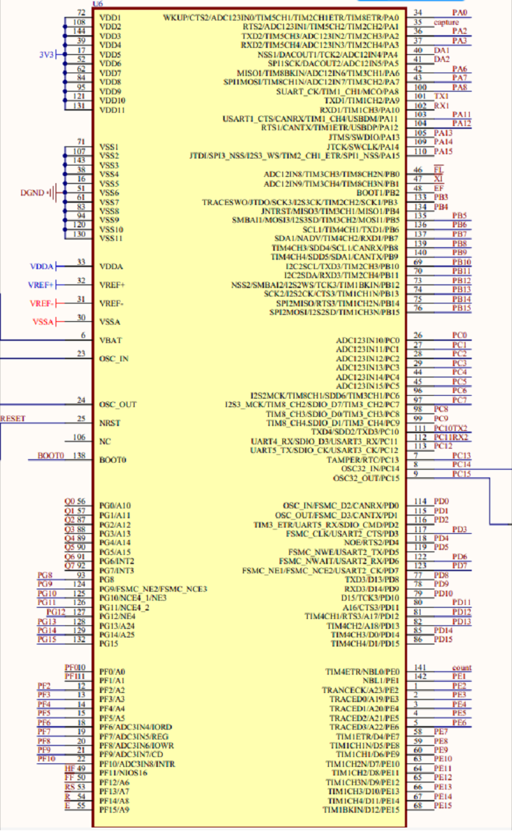
Overview of STM32F103ZET6 ResourcesThe STM32F103ZET6 chip features a Cortex-M3 core, 144 pins, 64KB sram, 512KB FLASH, 2 basic timers, 4 general-purpose timers, 2 advanced timers, 3 SPI interfaces, 2 I2C interfaces, 5 UARTs, 1 USB interface, 1 CAN interface, 3 12-bit ADCs, 1 12-bit DAC, 1 SDIO interface, 1 FSMC interface, and 112 general I/O ports. This chip configuration is notably robust and includes an external bus (FSMC) that can be used to expand SRAM and connect to LCDs. By driving the LCD through FSMC, the screen refresh rate can be significantly improved. This design utilizes one ADC with DMA transfer mode, which frees up the CPU for better processing. Each time a DMA process completes, it triggers the DMA completion interrupt to collect and calculate the heart rate value. The schematic diagram of the MCU is shown below.
Software Implementation of the System
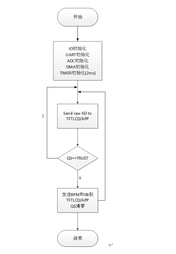
Program Function: The program enables the detection of data via the ADC port, as well as the acquisition, conversion, and processing of ECG signals. Ultimately, it displays the heart rate on a screen. Additionally, the heart rate can be transmitted to an upper-level application through Bluetooth. If the heart rate falls outside the set range, an alarm module will alert the user to pay attention to their health.In the process of program flow analysis, the most fundamental tool is the main program flowchart. It is the most basic and crucial technique in program analysis and represents a key step in the overall design. This flowchart concretely reflects our design approach. With the main program flowchart, we can decompose a complex software design into several functional modules and then design each module's function individually. After system initialization, tasks such as timer interrupts and display functions are performed, with different external hardware controlling various subroutines.The main program flowchart is shown in the figure below.
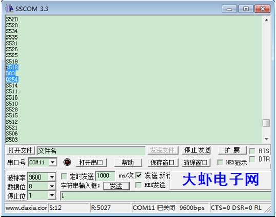
Timer Interrupt ProgramProgram Function: Initialize IO ports and UART port, setting the baud rate to 115200. Initialize the timer interrupt, if a heartbeat is detected, send the heart rate value to the upper computer APP, and clear the heartbeat detection flag. Otherwise, continue sending the heart rate value to the upper computer APP in an endless loop. The timer interrupt program is shown in Figure 4-2.Upper Computer APP ProgramProgram Function: This program requires Android 4.3 and above systems, with a phone that has a built-in Bluetooth 4.0 chip. Configure the Bluetooth module of the device, search for Bluetooth devices, establish Bluetooth socket communication, and finally display the heart rate values sent from the serial port.System DebuggingProgram DesignIn software design, a modular programming approach is generally used. An important part of the software construction activities is to provide procedures for solving specific problems by dividing a multifunctional complex program into several simple, single-function program modules, including stages such as analysis, design, coding, testing, and debugging. Modular programming also facilitates optimization and division of labor, improving program readability. Each program module should complete a specific task, implement a particular function, or initialize a system, and can be called as needed.The accuracy of heart rate values and the integrity of pulse waveforms are greatly related to the contact between the sensor and the finger. To achieve good and accurate experimental results, please note the following:Ensure good contact between the fingertip and the sensor; do not press too hard, as poor blood circulation may affect measurement results.Stay calm and avoid excessive movement during measurement, as this can affect measurement results.Do not use cold fingers for detection, as poor blood circulation may affect measurement outcomes.Maintain constant background light during measurement to reduce backlight interference.Module DebuggingAccording to the system design scheme, it can be divided into analog signal debugging part, microcontroller control circuit part, and upper computer APP debugging part. Due to the modular design of the system, it facilitates step-by-step testing of each circuit module, allowing errors to be clearly identified and improved upon.Sensor Part DebuggingUse an oscilloscope for measurement, connect the power and ground pins according to the pin order. Connect the oscilloscope probe to the output pin (S), set the time scan range of the oscilloscope to around 200ms, and the voltage scan range to about 2V. Set the oscilloscope probe to DC coupling (DC). As shown in Figure 5-1, the measured waveform indicates that the sensor is functioning correctly.Serial Port DebuggingThe program mainly outputs data through the USART serial port, with all outputs in ASCII code format and a baud rate of 9600. "S" prefix represents the numerical representation of the heart rate graph; "B" prefix represents the heart rate value; "Q" prefix represents the IBI value, i.e., the time between two adjacent heartbeats. "S" data is sent every 20ms due to the large amount of data. “B” and “Q” data are sent only once per detected effective heartbeat after each heartbeat, as shown in the figure.
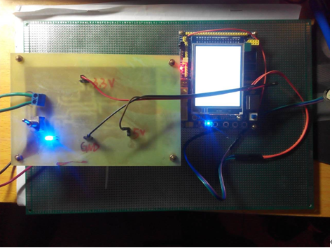
Debugging of the Upper Computer APP:When the software is opened, the following interface will appear, asking whether to enable Bluetooth. Click "Confirm" and then scan for devices. Once a device is detected, connect to the Bluetooth. At this point, the red indicator light on the Bluetooth will stop flashing.System DetectionAfter powering on the system, wait for the test state.The data in the test state are as follows: Signal indicates the collected signal value, and BPM represents the detected heart rate value. The LED light on the left side simulates the heartbeat state, displaying data during the measurement, as shown in Figure 5.
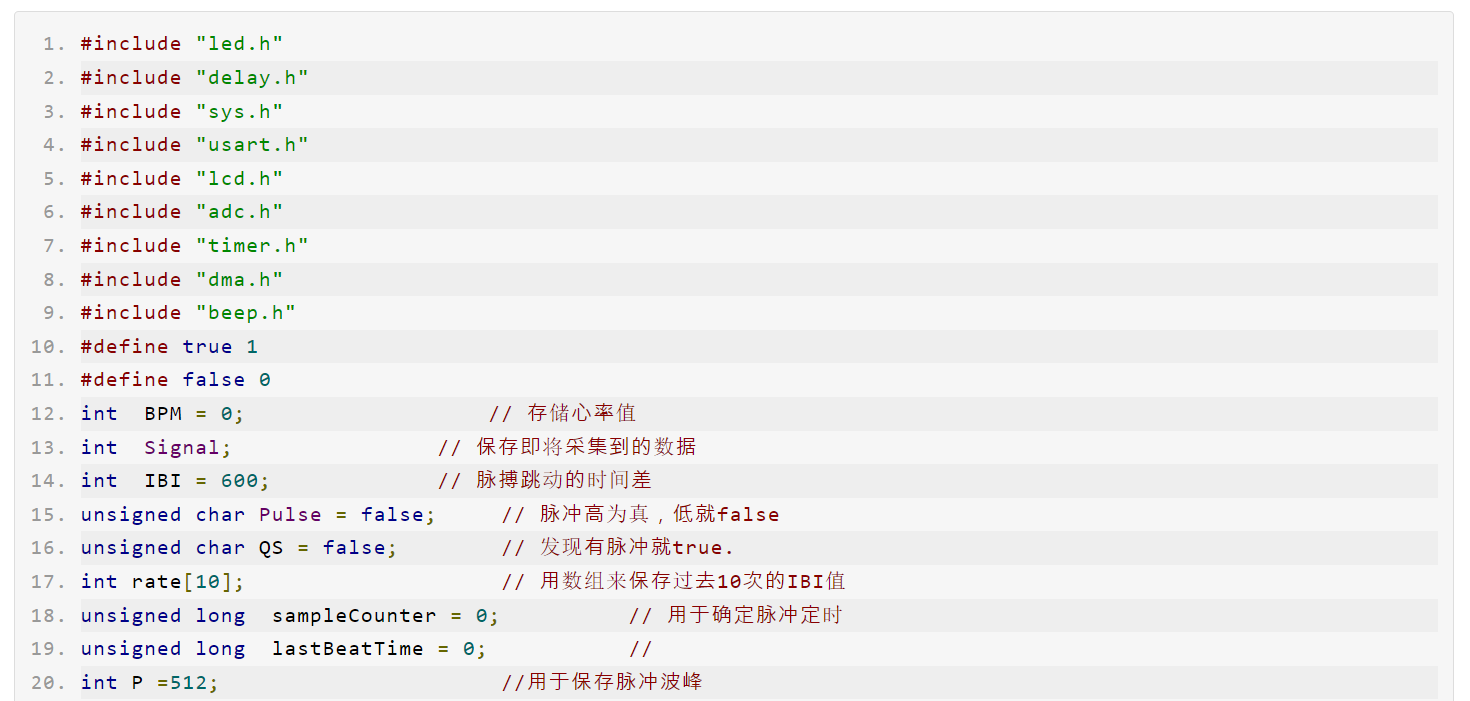
Heart rate sensor module program
Summary
The heart rate detection system designed in this project is user-friendly, widely applicable, and practically valuable. However, due to the short development period and my limited knowledge, although the basic functions have been achieved, there are still many shortcomings. These include high program redundancy, low sensitivity of the heart rate sensor, and less aesthetically pleasing display on the upper computer. Additionally, it lacks user-friendly features such as a voice system for automatic heart rate reading. The complexity of the modules has also increased the difficulty of power management during the design process. Nevertheless, with the continuous advancement of technology and medical science, the functions of heart rate monitors will inevitably improve, their application fields will expand, and they will become more portable. The ongoing development of electronic technology will continue to enhance our health and bring more convenience and excitement to our lives.