1kΩ Resistor Color Code Explained: From Color Bands to Selection & Application
What is a 1kΩ Resistor?
1kΩ resistors, with their fixed resistance value of 1,000 ohms, are indispensable in electronic circuits. They serve crucial functions such as current limiting, voltage division, and signal conditioning. Their widespread use in electronic design is facilitated by standardized color band coding, making them easily identifiable, and a variety of parameter options that cater to diverse application scenarios.
1. Resistance Value Definition and Identification
Resistance (symbol R) is a physical quantity representing a conductor's ability to impede current flow. Its essence stems from collisions between free electrons and atomic nuclei or lattice defects within the conductor: during current flow (directional movement of charge), free electrons collide with atomic nuclei and lattice defects, converting part of the electrical energy into heat (Joule heating). This characteristic, “impeding charge movement,” defines resistance.
In practical applications, resistance values are primarily marked through two methods: color band coding (the most common method for through-hole and traditional resistors) and direct printing (for surface-mount resistors (SMD Resistor)). Color band coding is widely adopted due to its durability and compatibility with multiple packaging types.
2. What the “1kΩ” Value Means in Circuits
1kΩ resistors are total workhorses in electronic circuits—super versatile and practical. The best part? They strike that sweet spot between performance and usability, making them suitable for a wide range of scenarios. You’ll usually see ’em used for current limiting, keeping sensitive parts like LEDs and low-power sensors safe from damage.
-
Limit current to protect sensitive components (LEDs / sensors)
This is one of the 1kΩ resistor’s core jobs—and it’s all based on Ohm’s Law (current = voltage difference ÷ resistance). When the voltage difference in your circuit pairs with that 1kΩ resistance, the current stays locked in a safe range—no component burnout, plain and simple.
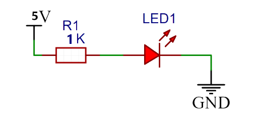
a. Protecting LEDs: In the LED circuit, standard LEDs have a forward voltage drop of approximately 2V to 3V. When powered by a 5V supply, adding a 1kΩ resistor in series limits the current to 2mA to 3mA. This falls within the LED's safe operating current range (1 mA to 20 mA), ensuring proper illumination without damage.
b. Protecting Low-Power Sensors: Stuff like photoresistors or DHT11 temp/humidity sensors only run on a few milliamps—hook ’em straight to a 5V supply, and you’re asking for overcurrent damage. Toss a 1kΩ resistor in series, though, and you’ll cap the max current at 5mA—perfect for most low-power sensors out there.
Heads up: This trick’s optimized for low-voltage circuits (3V to 12V). In that range, a 1V to 10V voltage difference lines up with a 1mA to 10mA current limit—a total perfect match. If your supply voltage is excessively high (such as 220V), a 1kΩ resistor’s current-limiting capabilities are weak. You need to replace it with a resistor of significantly higher resistance instead.
-
Forming a Voltage Divider to Obtain Precise Intermediate Voltage
The core principle of a voltage divider is “series resistance voltage division.” The 1kΩ resistor, being commonly available and easy to pair, is an ideal choice for constructing voltage dividers. When a 1kΩ resistor (R₁) is connected in series with another resistor (R₂), the total voltage is distributed proportionally to the resistances.
a. The intermediate voltage calculation formula is: Intermediate Voltage = Total Voltage × (R₁ ÷ (R₁ + R₂))
b. Application Example: Generating a 5V intermediate voltage from a 12V power supply. Assuming one kΩ as the lower resistor (R₁ = 1 kΩ), substituting this value into the formula yields an approximate upper resistor (R₂) of 1.4 kΩ. Selecting a standard 1.5kΩ resistor is sufficient, as the error falls within acceptable limits. For high-precision requirements, using resistors with a 1% tolerance can meet the demands of microcontroller ADC sampling, sensor power supply, and similar applications.
Note: The load current after voltage division must be significantly lower than the series current of the divider (recommended load resistance ≥ 10 times the divider resistor). Otherwise, it will affect the accuracy of the voltage division. A 1kΩ resistor balances the series current and power dissipation, adapting to the input impedance of most loads.
-
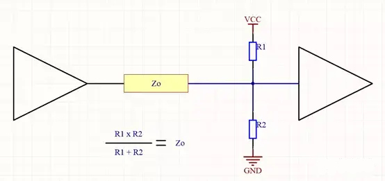
Impedance Matching for Signal Integrity
Impedance matching is make-or-break for keeping signals intact in electronic circuits—no cutting corners! A 1kΩ resistor checks the box for all sorts of signal circuits, from low-frequency to mid-to-high-frequency. That means your signals transmit dead-on accurate, with no distortion messing things up.
a. UART Serial Communication: Most microcontroller UART pins have output impedance between a few hundred ohms and 1kΩ. If your communication cable—like DuPont wire—has a characteristic impedance around 1 kΩ, slap a 1 kΩ resistor in series or parallel, and boom, impedance matching’s sorted. This reduces signal noise during transmission, addressing issues such as overshoot/undershoot when switching between high/low levels. I check and Measure Resistor Value with a Digital Multimeter, and it handles speeds ranging from 9600 bps to 115200 bps without issue. I check and measure the Resistor Value. I check and measure the Resistor Value with a Digital Multimeter.
b. Sensor Signal Output: Analog sensors like strain gauges and thermocouples typically have output impedances around 1kΩ. Suppose the subsequent amplifier circuit's input impedance is designed to be one kΩ (achieved by the parallel connection of a one kΩ resistor). In that case, it maximizes signal transmission efficiency and prevents signal attenuation.
Note: 1kΩ is only suitable for low-frequency digital/ Analog circuits; high-frequency RF circuits typically have characteristic impedances of 50Ω/75Ω, making 1kΩ resistors unsuitable.
-
Reference resistors in feedback networks stabilize active components
Amplifiers (op-amps, transistors), voltage regulator chips, and other active components require reference resistors in their feedback networks to set gain, output voltage, or operating points. The 1kΩ resistor is commonly used as a reference resistor due to its stable value and ease of matching.
a. Op-amp Non-inverting Amplifier Circuit: The gain formula for a non-inverting amplifier is Gain = 1 + (Feedback Resistor ÷ Reference Resistor). If a one kΩ resistor is used as the reference, pairing it with a 10 kΩ standard feedback resistor achieves an 11-fold gain. This circuit is stable and easy to implement.
b. Adjustable voltage regulator chips (e.g., LM1117): The output voltage is calculated as Output Voltage = 1.25V × (1 + (Feedback Resistor ÷ Reference Resistor)). If one kΩ is set as the reference resistor and a 3.3V output is desired, a standard 1.6 kΩ or 1.8 kΩ feedback resistor can be selected, with the error falling within the chip's tolerance range.
Note: The ratio between the one kΩ resistor and the feedback resistor must be matched based on the parameters of the active components (e.g., op-amp input bias current, regulator chip reference voltage). It is recommended to use high-precision resistors with a tolerance of 1% or lower to prevent reference drift from affecting circuit stability.
Quick Color Code for 1kΩ Resistors
Resistor color bands indicate resistance value (Resistance), tolerance (Tolerance), and sometimes temperature coefficient (Temperature Coefficient). Typically featuring 3 to 6 bands, the four-band color code is the industry standard for general-purpose resistors.
1. Decoding Three-Band and Four-Band Codes
- Three-Band Code: Composed of a significant digit band and multiplier band. The 1kΩ resistor code is Brown-Black-Red.
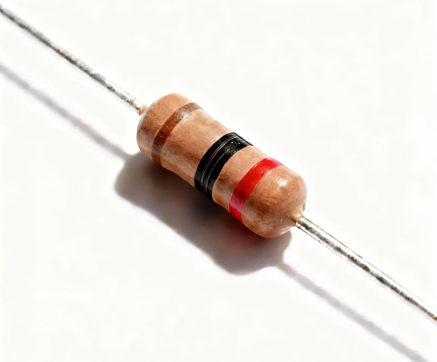
Brown (First Band): 1 (First Significant Digit)
Black (Second Band): 0 (Second Significant Digit)
Red (Third Band): ×100 (Multiplier)
Calculation: 10 × 100 = 1000Ω = 1kΩ (default tolerance ±20% when unspecified)
b. Four-Band Code: Adds a tolerance band for higher precision. A typical 1kΩ resistor code is Brown-Black-Red-Gold.
Brown (First Band): 1 (First Significant Digit)
Black (Second Band): 0 (Second Significant Digit)
Red (third band): ×100 (multiplier)
Gold (fourth band): ±5% (tolerance)
Calculation: 10 × 100 = 1000Ω = 1kΩ (tolerance ±5%)
2. Five-Band and Six-Band Code Analysis
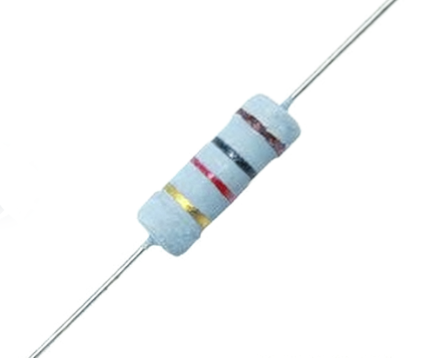
a. Five-band color code: Used for high-precision resistors, containing three significant digit bands. 1kΩ is coded as Brown-Black-Black-Brown-Gold.
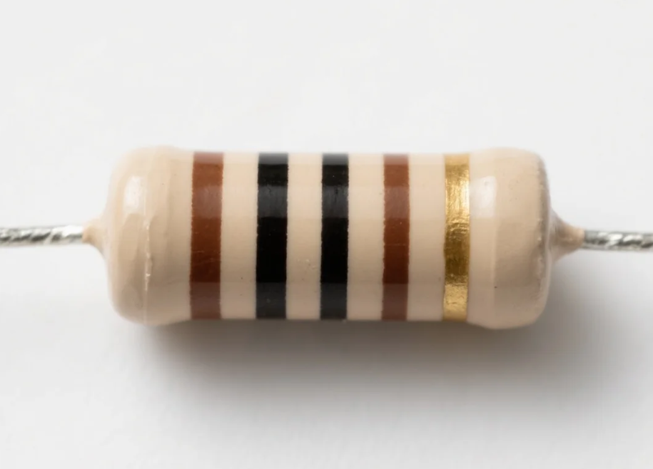
Brown (first band): 1 (first significant digit)
Black (second band): 0 (second significant digit)
Black (third band): 0 (third significant digit)
Brown (fourth band): ×10¹ (multiplier)
Gold (fifth band): ±1% (tolerance)
Calculation: 100 × 10 = 1000Ω = 1kΩ (±1% tolerance)
b. Six-Band Resistor: Includes a temperature coefficient band. Common 1kΩ model: Brown-Black-Black-Brown-Gold-Blue.
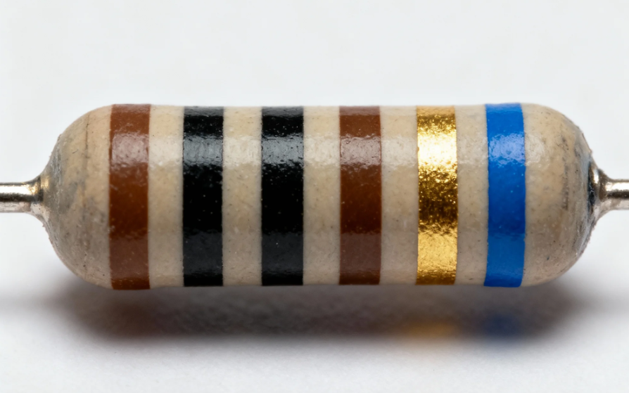
The first five bands follow five-band rules (1kΩ, ±1% tolerance).
Blue (sixth band): 10 ppm/°C (Temperature coefficient, indicating resistance change per degree Celsius).
3. Tips for Reading Colour Codes & Avoiding Mistakes
Read color bands starting from the end closest to the resistor's edge; the tolerance band (typically gold/silver) is often marked separately with a wider gap.
You can use a resistor color code chart reference for quick lookup, especially when distinguishing between similar hues (e.g., reddish-brown/grayish-white).
In critical applications, verify resistance values with a multimeter to account for potential color fading or printing errors.
Note for six-band resistors: The sixth band always indicates temperature coefficient, not tolerance.
Beyond Color Codes: Key Selection Parameters
Color bands only indicate resistance value and tolerance. To ensure optimal performance, consider these critical parameters when selecting 1kΩ resistors:
1. Power Rating
Power Rating specifies the maximum power a resistor can handle without overheating. Common power ratings for 1kΩ resistors are ¼W, ½W, 1W, and 2W.
- Low-power scenarios (¼W and ½W): Suitable for low-power circuits like signal paths and logic control.
- High-Power Applications (1W and 2W): Used in power supply circuits, LED current limiting, and other high-power applications.
Power Calculation Examples:
- 5V Circuit: Ideal maximum power dissipation P = V^2/R = 5^2/1000 = 25mW. A ¼ W (250 mW) resistor provides ample margin.
- 12V Circuit: Maximum power dissipation P = 12²/1000 = 144mW. Selecting W (250mW) or W (500mW) is a safe choice.
2. Accuracy and Tolerance
Tolerance refers to the permissible deviation of the resistance value from the nominal value. Common grades include ±5% (four-band gold mark), ±1% (five-band gold mark), ±0.5% (five-band red mark), and ±0.1% (high-precision resistors).
- General-purpose circuits (e.g., pull-up/pull-down resistors) may use ±5% tolerance.
- Precision applications (e.g., voltage dividers, sensor calibration) require ±1% or higher precision tolerance.
3. Material Type
Core material affects stability, noise, temperature coefficient, and other performance metrics:
- Carbon Film Resistors: Cost-effective for general-purpose circuits, with tolerance ranges from ±5% to ±10%.
- Metal film resistors: Higher precision (±1% or better), lower noise, and superior temperature stability, suitable for audio and signal processing circuits.
- Thick film resistors: High durability, suitable for surface-mount applications, with good power handling capability.
4. Temperature Coefficient
The temperature coefficient (ppm/°C) indicates the degree to which the resistance value changes with temperature. Lower values indicate better stability:
- Carbon film: ±150 to ±200 ppm/°C
- Metal film: ±25 to ±100 ppm/°C
- High-precision metal film: ±10 to ±25 ppm/°C
5. Packaging and Size Considerations
Packaging type and dimensions depend on mounting techniques and space constraints:
- Through-Hole Technology (THT): Axial lead packages (e.g., 0207, 0410) are suitable for breadboards and traditional printed circuit boards (PCBs).
- Surface Mount Technology (SMT): Chip resistors (e.g., 0402, 0603, 0805) are suitable for compact, high-density designs.
- Larger packages (e.g., 1206, 2512) are used for higher power ratings (1W and above).
Typical Applications of 1kΩ Resistors
1kΩ resistors are widely used in consumer electronics, industrial control, and automotive systems:
1. Current-Limiting Circuits
Used to restrict current flowing through LEDs, transistors, and sensors to prevent burnout. For example, connecting a 1kΩ resistor in series with an LED to a 5V power supply limits current to approximately 3-4mA (safe for most LEDs).
2. Voltage Divider Applications
Constructing voltage divider networks reduces the input voltage to a level that is measurable or usable. Commonly found in analog-to-digital converter (ADC) circuits and sensor signal conditioning.
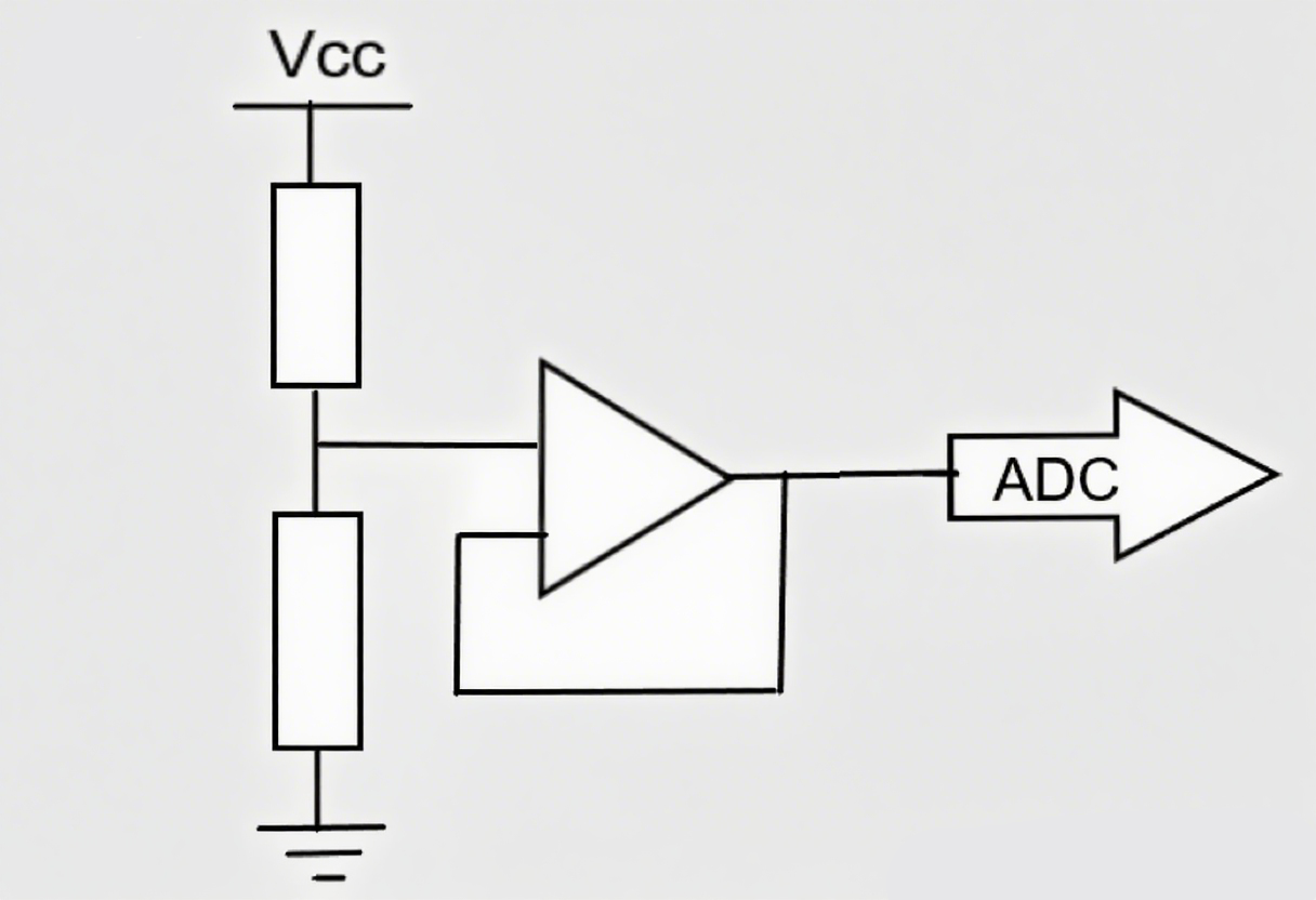
Voltage-Divider-Circuit Designs
3. Pull-Up/Pull-Down Resistors
In digital circuits, pull-up resistors connect input pins to VCC to ensure stable high logic levels, while pull-down resistors connect to ground (Gnd) to ensure stable low levels. This prevents floating pins and abnormal behavior.
Pull-Up/Pull-Down Resistors Circuit Designs
4. Bias, Signal Conditioning, and Feedback Networks
Provides a bias current to transistors and operational amplifiers (OP-amps) to establish the correct operating point.
Conditions analog signals by filtering noise or matching impedances between components.
Serves as a feedback resistor in amplifiers and voltage regulators (VRs) to stabilize gain and output voltage.
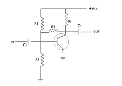
Voltage-divider Biased Common - Emitter Amplifier Circuit Designs
5. Comparison of 1kΩ vs 10kΩ and Other Resistance Values
|
Comparison Object |
Core Differences |
Suitable Scenarios |
|
1kΩ vs 10kΩ |
1kΩ has lower impedance; 10kΩ features lower power consumption and higher impedance |
1kΩ is suitable for high-current scenarios; 10kΩ is ideal for low-power, high-impedance circuits (e.g., MCU input pins) |
|
1kΩ vs 100Ω |
100Ω is compatible with higher-current loads; 1kΩ balances current limiting and power consumption |
100Ω is used in high-current load circuits; 1kΩ applies to most general current-limiting and voltage-dividing scenarios |
How to Test & Read Quickly (Practical Guide)
1. Multimeter Testing Method
- Set the multimeter to resistance measurement mode (Ω), selecting a range slightly above 1kΩ (e.g., 2kΩ or 20kΩ).
- Calibrate multimeter if necessary (analog models): Short-circuit test leads and adjust the zero knob.
- Connect test leads to both ends of the resistor (no polarity required for non-polarized resistors).
- Read the displayed value; a properly functioning 1kΩ resistor should show within its tolerance range (e.g., 950Ω to 1050Ω for ±5% tolerance).
Tip: You may use the Resistor Color Code Calculator to obtain the result directly.
2. Color Code Conversion Table + Application Table
|
Color |
Significant Figure |
Multiplier |
Tolerance |
Temperature Coefficient |
|
Black |
0 |
×10⁰ |
- |
- |
|
Brown |
1 |
×10¹ |
- |
10 ppm/°C |
|
Red |
2 |
×10² |
- |
50 ppm/°C |
|
Orange |
3 |
×10³ |
- |
- |
|
Yellow |
4 |
×10⁴ |
- |
- |
|
Green |
5 |
×10⁵ |
±0.5% |
20 ppm/°C |
|
Blue |
6 |
×10⁶ |
±0.25% |
10 ppm/°C |
|
Violet |
7 |
×10⁷ |
±0.1% |
5 ppm/°C |
|
Gray |
8 |
×10⁸ |
±0.05% |
- |
|
White |
9 |
×10⁹ |
- |
- |
|
Gold |
- |
×10⁻¹ |
±5% |
- |
|
Silver |
- |
×10⁻² |
±10% |
- |
Application Table:
|
Resistor Type |
Color Code |
Application Scenario |
|
General-purpose 1kΩ (4-band) |
Brown-Black-Red-Gold |
Consumer electronics, breadboards |
|
Precision 1kΩ (5-band) |
Brown-Black-Black-Brown-Gold |
Industrial controls, sensor circuits |
|
High-stability 1kΩ (6-band) |
Brown-Black-Black-Brown-Gold-Blue |
Medical devices, aerospace electronics |
3. Common Errors and Troubleshooting
- Color code reading error: Recheck the band sequence (starting from the band closest to the edge) and use the color code reference table.
- Multimeter reading exceeds tolerance range: The resistor may be damaged (overheated or burned out), or the multimeter range setting is incorrect. Change the range or replace the resistor.
- Intermittent resistance fluctuations: Loose solder joints or damaged resistor body; resolder or replace the component.
- Confusion between brown and red bands: Use natural light for identification—brown bands appear darker with a reddish tint, while red bands are brighter.
Purchasing & Distributor Considerations
1. Brand and Certification
Select well-known resistor brands with industry certifications to ensure quality and reliability:
- Vishay: Offers high-precision metal film resistors with tight tolerances and low temperature coefficients.
- YAGEO: Provides cost-effective carbon film and thick film resistors for general applications.
- KOA Speer: Specializes in high-power and high-stability resistors for industrial and automotive sectors.
- unikeyic: A leading enterprise in the electronics industry, specializing in electronic component supply chain services.
Certification Requirements: Focus on environmentally compliant certifications such as RoHS (Restriction of Hazardous Substances) and ISO quality system certifications to ensure consistent manufacturing standards.
2. Bulk Procurement Strategy and Inventory Management
- Volume Pricing: Negotiate volume discounts with distributors when purchasing large quantities (e.g., 1000+ units).
- Inventory Control: Maintain stock of commonly used specifications (¼W, ½W, ±5% and ±1% tolerance) to prevent project delays.
- Lead Time: Confirm delivery schedules with distributors, especially for high-precision or custom resistors (lead times may reach 2-4 weeks).
3. Acceptance Inspection Key Points
Upon receiving resistors, verify:
- Lot Number: Ensure production batch consistency to maintain performance stability.
- Packaging: Surface-mount resistors must be packaged in anti-static bags; through-hole resistors must use tape reels to prevent damage.
- Markings: Color bands must be clear with uniform spacing; printed values on surface-mount resistors must be legible.
- Physical Condition: No cracks, discoloration, or bent leads (for through-hole resistors).
4. Recommended Typical Specifications List
|
Application |
Power Rating |
Tolerance |
Material |
Package Type |
|
Hobby projects/breadboards |
¼W |
±5% |
Carbon film |
Axial THT |
|
Arduino/Raspberry Pi circuits |
½W |
±5% |
Carbon film |
0805 SMD |
|
Audio amplifiers |
½W |
±1% |
Metal film |
0603 SMD |
|
Industrial controls |
1W |
±1% |
Metal film |
Axial THT (0410) |
|
Medical devices |
½W |
±0.5% |
High-stability metal film |
0805 SMD |
|
Automotive electronics |
1W |
±1% |
Thick film |
1206 SMD |
Frequently Asked Questions
1. What is the value of a 1K resistor?
The nominal resistance value of a 1k resistor is 1000 ohms (Ω), or 1 kilo ohm (kΩ). The actual value may fluctuate within the resistor's tolerance range (e.g., 950Ω to 1050Ω for ±5% tolerance).
2. What is the use of a 1K resistor?
1k resistors are used for current limiting (e.g., LEDs, sensors), voltage division, pull-up/pull-down in digital circuits, bias circuits for transistors/amplifiers, signal conditioning, and feedback networks. Their applications span consumer electronics, industrial control, automotive systems, and IoT devices.
3. What is the colour code for 1000 ohm resistance?
- Four-band resistors: Brown-Black-Red-Gold (±5% tolerance) or Brown-Black-Red-Silver (±10% tolerance).
- Five-band resistors: Brown-Black-Black-Brown-Gold (±1% tolerance) or Brown-Black-Black-Brown-Red (±2% tolerance).
- Three-band resistor: Brown-Black-Red (±20% tolerance, default).
4. What is the pattern of a 10k resistor?
- 10k resistors (10,000Ω) use the following color bands:
- Four-band resistor: Brown-Black-Orange-Gold (±5% tolerance).
- Five-band resistor: Brown-Black-Black-Red-Gold (±1% tolerance).
- Calculation: Brown (1) + Black (0) + Orange (×1000) = 10 × 1000 = 10,000Ω = 10kΩ.