Nanofarad Capacitors: Basics and Applications
| Table of Contents |
What Is a Nanofarad Capacitor (nF)?
A nanofarad capacitor (nF) is one of the commonly used capacitive electronic components in various electronic devices (such as smartphones, industrial controllers, and communication terminals) and electronic circuits, characterized by its capacitance value measured in nanofarads. As a fundamental circuit element for storing electric charge, nanofarad-level capacitors play a crucial role in various circuit scenarios, including signal processing, power filtering, and timing control, due to their moderate capacitance range.
Definition of nF
nF is the Standard abbreviation for the capacitance unit "nanofarad." One nanofarad (nF) equals 10^-9 farads (F). While the farad is the fundamental unit of capacitance, its magnitude is too large for direct use in practical electronic circuits. Smaller derived units are typically employed, with nanofarads being one of the most widely used. In terms of conversion relationships, 1 nF equals 1000 picofarads (pF) and 0.001 microfarads (μF). This conversion relationship positions nF as a vital bridge between the commonly used units of picofarads and microfarads, facilitating the expression and application of capacitors across different capacitance ranges.
Capacitance Unit Hierarchy (pF → nF → µF)
The capacitance unit system for electronic circuits is based on the farad (F), with units increasing in magnitude as follows: picofarad (pF), nanofarad (nF), and microfarad (μF). Conversion between units follows a base-1000 system. The hierarchical relationships and typical applications are as follows:
• Picofarad (pF, 10⁻¹² F): A low-capacitance unit commonly used in high-frequency circuits such as RF circuits and oscillators. It enables functions like signal filtering and coupling, typically ranging from several picofarads to several thousand picofarads.
• Nanofarad (nF, 10⁻⁹ F): Occupies an intermediate tier in the unit hierarchy, with capacitance between picofarads and microfarads. It suits a broader range of circuit applications, handling both mid-to-high-frequency signal processing and participating in mid-to-low-frequency filtering tasks. Capacitance typically spans from 1nF to 1000nF (equivalent to 1μF).
• Microfarad (μF, 10⁻⁶ F): A medium-to-large capacitance unit primarily used in scenarios requiring significant charge storage, such as power supply filtering, voltage smoothing after rectification, and motor start circuits. Common capacitance ranges from several microfarads to thousands of microfarads.
This unit system allows circuits with varying capacitance requirements to find suitable electronic component specifications for capacitors. The existence of nanofarad units effectively bridges the gap in capacitance representation between picofarads and microfarads, simplifying the expression of intermediate capacitance ranges.
What Is a Nano Capacitor?
The term "Nano Capacitor" has two distinct meanings in the industry:
• Common Interpretation (In Engineering & Procurement Contexts):
While rarely used by professionals, "Nano Capacitor" may appear as a colloquial search term or in informal usage, essentially referring to a capacitor with a value in the nanofarad range—an "nF capacitor." This is the type most frequently encountered in general electronic design and projects.
• Specialized Meaning (In Research Fields):
In nanotechnology and advanced materials research, a nano capacitor refers to experimental capacitors that utilize nanomaterials or nanostructures. This meaning is specific to cutting-edge research and is unrelated to the procurement of standard electronic components.
Why are nF values commonly used in circuits?
Capacitors in the nanofarad (nF) range are widely used because their capacitance values align closely with typical functional requirements. This balance between component performance and practicality can be analyzed from the following perspectives:
• Strong capacity adaptability. Many circuit uses do not need the high-frequency features of picofarad capacitors. They also do not need the large energy storage of microfarad capacitors. Instead, they demand intermediate capacitance values to fulfill specific functions. For instance, in audio circuits, nF-level capacitors serve as coupling capacitors, effectively transmitting audio signals while blocking DC components. In digital circuits, they function as decoupling capacitors, suppressing high-frequency noise and stabilizing chip supply voltages.
• Second, unit conversion is straightforward. Since 1nF = 1000pF and 1nF = 0.001μF, the nF unit provides a flexible bridge for electronic circuits during design and component selection. When design requirements fall between these two scales, using nF notation avoids the need for extensive decimals or scientific notation, simplifying design documentation and component parameter reading.
• Finally, component manufacturing is mature. Through long-term technological development, production processes for nF-level electronic components (capacitors) have reached high maturity. Whether ceramic, film, or electrolytic capacitors, a wide range of nF-level products is readily available. These offer controllable costs, high stability, and meet the bulk application demands in electronic circuits for consumer electronics, industrial control, communication equipment, and other fields.
nF, µF, pF Conversion Guide
Proficient conversion between nanofarads (nF), microfarads (µF), and picofarads (pF) is a fundamental skill in electronic design and maintenance. This guide offers clear and rapid conversion methods.
What is 1 nF equal to?
1 nF (nanofarad) is a fundamental unit with the following conversion relationships:
•1 nF = 0.001 µF (one-thousandth of a microfarad)
•1 nF = 1000 pF (one thousand picofarads)
Simply put, nF is an intermediate unit between pF and µF.
Is 100 nF equal to 0.1 µF?
Yes, absolutely correct.
This is one of the most common and essential equivalence relationships in electronics.
Since 1 µF = 1000 nF,
then 100 nF = 100 / 1000 µF = 0.1 µF.
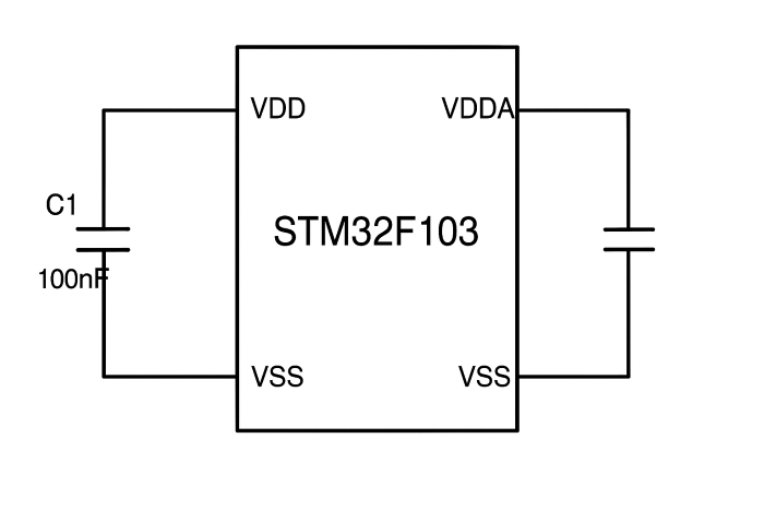
In circuit diagrams (e.g., schematic diagrams of electronic devices) and Bill of Materials (BOM), 0.1µF and 100nF denote the same capacitance value and are interchangeable, which is a key point to note when reading circuit diagram labels. It is commonly used as a decoupling capacitor for integrated circuit (IC) power pins.
How to convert microfarads to nanofarads?
Converting microfarads (µF) to nanofarads (nF) is straightforward, following one rule:
Multiply the µF value by 1000 to obtain the nF value.
Conversion formula: nF = µF × 1000
• How many nF are in 2.2 µF?
• What is 0.47 µF in nF?
0.47 × 1000 = 470 nF
•How many nF is 1 µF?
1 × 1000 = 1000 nF
Quick Formula Reference
To meet quick conversion needs across different scenarios, here are the core conversion formulas between nF, µF, and pF, covering all common conversion directions for direct application:
• nF → pF: Picofarad value (pF) = Nanofarad value (nF) × 1000 (since 1nF = 1000pF)
• nF → µF: Microfarad value (µF) = Nanofarad value (nF) ÷ 1000 or Nanofarad value (nF) × 0.001 (since 1 µF = 1000 nF)
•µF → nF: Nanofarad (nF) = Microfarad (µF) × 1000 (inverse operation of nF→µF)
•µF → pF: Picofarad (pF) = Microfarad (µF) × 10⁶ (Derived via two steps: µF→nF→pF, where 1µF=1000nF=1000×1000pF=10⁶pF)
• pF → nF: Nanofarad value (nF) = Picofarad value (pF) ÷ 1000 or Picofarad value (pF) × 0.001 (inverse operation of nF→pF)
• pF → µF: Microfarad value (µF) = Picofarad value (pF) ÷ 10⁶ or Picofarad value (pF) × 10⁻⁶ (Derivable via pF→nF→µF two-step conversion)
Conversion Table
To visually present common capacitance conversion results, a conversion table for nF, µF, and pF is provided, covering typical capacitance values in circuits for direct reference:
|
Nanofarad (nF) |
Microfarad (µF) |
Picofarads(pF) |
|
0.1 nF |
0.0001μF |
100 pF |
|
0.47 nF |
0.00047 μF |
470 pF |
|
1nF |
0.001 μF |
1000 pF |
|
10nF |
0.01 μF |
10000 pF |
|
47nF |
0.047 μF |
47000 pF |
|
100nF |
0.1 μF |
100,000 pF |
|
220 nF |
0.22 μF |
220,000 pF |
|
470nF |
0.47 μF |
470,000 pF |
|
1000 nF |
1 μF |
1,000,000 pF |
Typical Value Ranges (1nF – 100nF – 470nF)
In practical circuit applications, 1nF, 100nF, and 470nF are three highly representative nF-level capacitance values covering core application scenarios for medium-capacity capacitors. Their corresponding conversion values and typical uses are as follows:
• Around 1nF (1nF–10nF)
When converted to other units: 1nF = 0.001µF = 1000pF, 10nF = 0.01µF = 10000pF. Capacitors in this range are commonly used in mid-to-high frequency signal processing scenarios, such as signal coupling in RF circuits, fine-tuning frequencies in low-frequency oscillation circuits, and suppressing high-frequency noise in digital circuits. Their moderate capacitance enables both signal transmission and minimization of high-frequency losses.
•100nF Range
100nF = 0.1µF = 100000pF.This is one of the most versatile capacitance values in electronic circuits. It is widely used as a power decoupling capacitor (e.g., near the power supply pins of microcontrollers or chips), effectively suppressing high-frequency interference on power lines and stabilizing the chip's operating voltage. It can also serve as a coupling capacitor in audio circuits, enabling signal transfer between stages while blocking DC.
•470nF Range
470nF = 0.47μF = 470,000pF represents a typical transition capacity between the nF and μF ranges. It is commonly used for filtering and bypassing in low-to-mid frequency circuits, such as output filtering in small power modules and interference suppression in motor control circuits. Its capacity satisfies certain energy storage requirements while offering faster response times compared to lower-capacity μF-level capacitors.
Real-World Applications of nF Capacitors
Nanofarad capacitors are important as "middle-size" capacitors. They play key roles in electronic circuits for filtering, decoupling, coupling, timing control, and electromagnetic compatibility (EMC). Different nF capacitance values exhibit distinct capacitive reactance characteristics, making them suited for specific applications. Below is a detailed analysis combining typical parameters with real-world circuit scenarios.
Filtering (10nF/22nF/47nF)
Filtering represents the most fundamental application for nF capacitors in electronic devices, serving to eliminate unwanted frequency signals from circuits." As capacitance increases from 10nF to 22nF to 47nF, capacitive reactance decreases, progressively extending the suitable filtering frequency range toward lower frequencies. Specific differences are as follows:
• 10nF Ceramic Capacitor: Features relatively high capacitive reactance, making it ideal for high-frequency filtering applications. Examples include noise filtering in RF circuits (frequencies above 1MHz) and suppressing high-frequency noise on high-speed signal lines in digital circuits. For instance, in the power supply lines of a WiFi module, a 10nF ceramic capacitor effectively filters RF signal interference from the power supply, preventing signal crosstalk.
• 22nF Ceramic Capacitor: Moderate capacitive reactance, suitable for both mid-high and mid-low frequency filtering. As a general-purpose filter capacitor, it is commonly used for power filtering in audio preamplifier circuits (20Hz-20kHz frequency range), effectively removing high-frequency noise introduced by the power supply while avoiding excessive attenuation of the audio signal. It can also be used for signal filtering on microcontroller I/O ports to stabilize output levels.
•47nF Ceramic Capacitor: Features low capacitive reactance, emphasizing mid-to-low frequency filtering. Applications include power filtering in small DC motor drive circuits (suppressing low-frequency ripple during motor startup) and current smoothing in LED backlight driver circuits. For instance, a 47nF capacitor in series with a 12V DC fan's power supply circuit reduces the impact on the motherboard's power supply during fan start/stop cycles.
Decoupling & Noise Suppression (100nF)
Decoupling and noise suppression are standard applications for nF capacitors. Among these, the 100nF (0.1μF) capacitor strikes an ideal balance between capacitance and response speed, making it the "first choice for circuit decoupling." Its core function is to provide a "local temporary power supply" for chips, suppressing noise on power lines.
Signal Coupling
The core requirement for signal coupling is "transmitting AC signals while blocking DC components." Capacitors in the nF range are the mainstream choice for coupling circuits because their capacitance suits most common AC signal frequencies (such as audio and low-frequency digital signals).
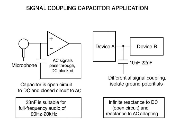
• Working Principle: Capacitors exhibit infinite reactance to DC signals (equivalent to an open circuit), while their reactance to AC signals increases as frequency rises. Selecting an appropriately sized nF capacitor allows the target AC signal to pass smoothly while blocking DC potentials between preceding and succeeding circuits, preventing mutual interference.
• Typical Applications: In audio circuits, the AC audio signal from a microphone must be coupled to the amplifier circuit via an nF capacitor. This facilitates signal transmission while isolating the DC potential difference between the microphone and amplifier, preventing damage to the amplifier chip. Common capacitance values range from 10nF to 47nF. For instance, a 33nF capacitor is well suited for the coupling of full-range audio signals from 20Hz to 20kHz. In differential communication circuits like RS-485, 10nF to 22nF capacitors are also used for signal coupling and impedance matching, isolating the ground potentials of different devices while optimizing signal transmission efficiency.
Timing / RC Circuits
In RC (resistor-capacitor) timing circuits, nF capacitors work with resistors to "control charge/discharge time," enabling functions like delay, oscillation, and waveform generation. Their capacitance directly determines the precision of timing parameters.
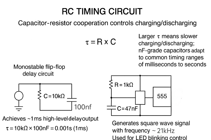
• Core Principle: The charging/discharging time constant τ of an RC circuit is τ = R × C (where R is the resistance value and C is the capacitance value). A larger τ results in slower charging/discharging speeds. Selecting nF-level capacitors places τ within the commonly used timing range of milliseconds to seconds, meeting the delay requirements of most circuits.
• Practical Example: In a monostable multivibrator circuit, adjusting the nF capacitor and resistor parameters sets the delay time for the high-level output. For example, pairing a 10kΩ resistor with a 100nF capacitor yields τ = 10kΩ × 100nF = 0.001s (1ms), achieving approximately 1ms delay. In a multivibrator circuit using a 555 timer, combining a 47nF capacitor with a 1kΩ resistor generates a square wave signal around 21kHz, suitable for LED flashing control.
EMI/EMC Applications
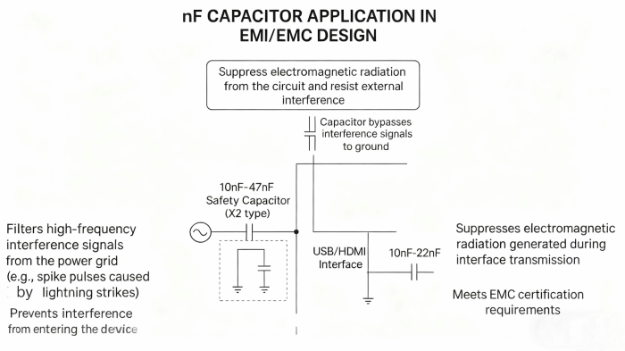
The core principle of EMI (Electromagnetic Interference)/EMC (Electromagnetic Compatibility) design is "suppressing circuit radiation while resisting external interference." Capacitors achieve anti-interference functionality by "bypassing interference signals to ground," making them fundamental components in EMC design.
Common Applications: In power input filter circuits, parallel-connecting 10nF-47nF safety capacitors (e.g., X2 capacitors) at the AC input filters out high-frequency interference signals introduced by the power grid (such as lightning-induced spike pulses), preventing interference from entering the device. In USB, HDMI, and similar interface circuits, a 10nF-22nF capacitor is connected in parallel between the signal line and ground to suppress electromagnetic radiation generated during interface transmission, meeting EMC certification requirements.
How to Read nF Capacitor Labels
Capacitors, especially small ceramic capacitors, have limited surface area. Therefore, a simplified code system is widely used to indicate their capacitance. Mastering this method is crucial for correctly identifying and using nF-level capacitors.
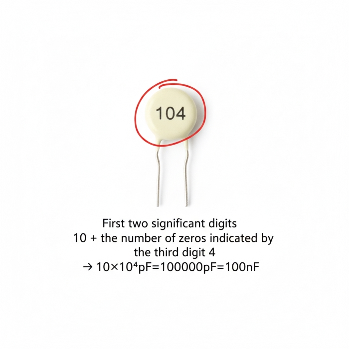
Direct Marking (103, 104, etc.)
This is the most common method for marking nF-level capacitors in circuit diagrams and component packaging, using a three-digit code that is easy to identify on circuit diagram schematics. The reading rules as follows:
• First two digits: Represent the significant figures of the capacitance value.
• Third digit: Indicates the number of zeros to be added after the significant digits.
• Unit: The final calculation result is in picofarads (pF). Since 1 nF = 1000 pF, we typically need to convert pF values to the more commonly used nF.
Digital Code Method
•The Digital Code Method is an extension of standard capacitor marking rules, widely applied to small surface-mount device (SMD) capacitors and multilayer ceramic capacitors (MLCCs). Modern capacitor markings typically follow the three-digit (or four-digit) coding system of the Electronic Industries Alliance (EIA), which uses picofarads (pF) as the base unit. The first two digits represent significant figures, and the third digit indicates the number of zeros to append. This is the most mainstream reading method for components like MLCCs, especially suitable for nanofarad (nF)-class capacitors. For example, the code "103" means 10 × 10³ pF, which converts to 10,000 pF (i.e., 10 nF); "104" is 100,000 pF (i.e., 100 nF), and "471" is 470 pF.
•It is important to clarify that letters in modern capacitor markings usually indicate tolerance rather than a multiplier, which is a key point prone to misunderstanding. Common tolerance marking rules are as follows: J represents ±5%, K represents ±10%, M represents ±20%, and Z represents +80/-20%. Taking "100K" as an example, its correct meaning is 100 pF with a tolerance of ±10%, not 100 nF derived from the incorrect assumption that "K is a multiplier" or "the default unit is nF". This rule of using letters to indicate tolerance is universal in modern MLCC markings and should be followed first.
•In the Digital Code Method, "R" is also used to replace the decimal point for marking small-capacity capacitors. For example, "R47" means 0.47 pF, "4R7" means 4.7 pF, and "1R0" means 1.0 pF. However, this rule only applies to standard ceramic MLCCs; some film capacitors (non-MLCCs) may directly use formats like "4n7" to indicate 4.7 nF, but this is is not standard for MLCCs In addition, letter-based multiplier coding methods such as A=10⁰ and B=10¹ are non-standard and rarely used in modern components. They occasionally appear in older or brand-specific capacitor series but should not be used as a reference for conventional reading methods.
SMD MLCC Size & Common Values
The size (package) of surface-mount multilayer ceramic capacitors (MLCCs) is strongly correlated with their common nF value ranges. Understanding this aids in circuit design and component selection.
• Package Naming
They are typically denoted by a four-digit code representing inches. For example:
0201: Length 0.02 inches × Width 0.01 inches
0402: Length 0.04 inches × Width 0.01 inches
0603: Length 0.06 inches × Width 0.03 inches
0805: Length 0.08 inches × Width 0.05 inches
1206: Length 0.12 inches × Width 0.06 inches
• Package Size vs. Common nF Values
|
Package Dimensions |
Physical Dimensions (Metric) |
Typical nF-Level Capacitance Range (Ceramic Capacitors) |
Common Examples (Code) |
|
0201 |
0603 (0.6×0.3mm) |
Below 1 nF |
1n0 (1.0nF), 2n2 (2.2nF) |
|
0402 |
1005 (1.0×0.5mm) |
1 nF ~ 100 nF |
103 (10nF), 104 (100nF) |
|
0603 |
1608 (1.6×0.8mm) |
100 nF ~ 470 nF |
104 (100nF), 474 (470nF) |
|
0805 |
2012 (2.0×1.25mm) |
470 nF ~ 1 μF |
474 (470nF), 105 (1μF) |
|
1206 |
3216 (3.2×1.6mm) |
1 μF and above |
105 (1μF), 226 (22μF) |
• Key Points:
Generally, larger package sizes enable higher maximum capacitance values. Therefore, common 100nF (104) decoupling capacitors most frequently use 0402 or 0603 packages, which offer a good balance between size and capacitance.
Electrical Characteristics & Selection Tips nF
Selecting the right nF capacitor directly determines circuit stability and reliability. Strict attention must be paid to the parameters specified in circuit diagrams.
Voltage Rating
The voltage rating (breakdown voltage) represents the "safety threshold" for nF capacitors, indicating the maximum voltage at which the capacitor can operate stably within its rated temperature range. Typically marked as "VR" (Voltage Rating) or "WV" (Working Voltage), exceeding this rating may cause dielectric breakdown, burnout, or even explosion.
• Core Selection Principle: The operating voltage must be lower than the rated voltage, with sufficient safety margin reserved. It is generally recommended that the operating voltage does not exceed 50%-70% of the rated voltage. In scenarios with power fluctuations or voltage spikes (e.g., power filtering, motor drives), a larger margin is required. For example, in a 12V circuit, select nF capacitors with a rated voltage of 16V or higher to prevent breakdown caused by power spikes.
• Common rated voltage values: Capacitors in the nF range typically have rated voltages of 6.3V, 10V, 16V, 25V, 50V, or 100V. Package size correlates positively with voltage rating—small packages like 0402/0603 typically support 6.3V to 25V, while 1206 and larger packages can handle 50V to 100V. Selection should balance package size and voltage requirements.
Dielectric Type: C0G, X7R, X5R
The dielectric material is the "core element" determining the performance of nF capacitors. C0G (NP0), X7R, and X5R are the three most commonly used dielectrics for ceramic nF capacitors. Their significant differences in temperature stability, capacitance accuracy, and cost directly influence their applicable scenarios:
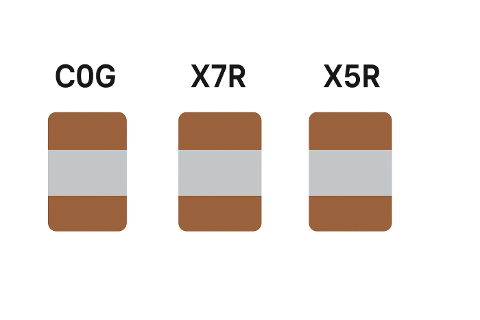
• C0G (NP0) Dielectric: Offers optimal temperature stability with a capacitance temperature coefficient of ±30ppm/℃. Capacitance variation is minimal across -55℃ to +125℃, achieving accuracy of ±1%/±2%. However, it features low capacitance density, resulting in smaller nF values for the same package size (e.g., max. ~10nF for 0805 package) and higher cost. Suitable applications: High-frequency oscillation circuits, precision timing circuits, and other scenarios demanding extreme capacitance stability.
• X7R Dielectric: A general-purpose dielectric with a temperature range of -55°C to +125°C and a capacitance variation of ±15%. It offers higher capacitance density than C0G (up to 100nF in 0805 packages) at moderate cost. Suitable for: Power filtering, decoupling, signal coupling, and most general-purpose applications. It is the preferred dielectric for nF capacitors in consumer electronics.
• X5R Dielectric: Temperature range -55°C to +85°C, capacitance variation ±15%, capacitance density similar to X7R, slightly lower cost. However, its high-temperature stability is inferior to X7R, making it unsuitable for high-temperature environments (e.g., automotive electronics, industrial control). Suitable for: Filtering and decoupling circuits in consumer electronics operating at ambient temperatures (e.g., smartphones, set-top boxes).
Selection Tips: Prioritize screening based on temperature environment and precision requirements—choose C0G for high-temperature or precision applications, X7R for general room-temperature scenarios, and X5R for low-cost room-temperature needs. Simultaneously ensure proper matching between dielectric and capacitance; for large-capacitance nF capacitors (e.g., 100nF and above), prioritize X7R/X5R dielectrics.
Temperature Coefficient
Temperature Coefficient (TC) indicates the rate of capacitance change with temperature, measured in ppm/℃ (parts per million per degree Celsius). It is categorized into Positive Temperature Coefficient (PTC), Negative Temperature Coefficient (NTC), and Zero Temperature Coefficient (e.g., C0G), directly impacting circuit performance stability across varying temperatures.
• Parameter Interpretation: For example, a C0G capacitor with a TC of ±30 ppm/°C indicates a maximum capacitance change of 0.003% per 1°C temperature variation. Conversely, some low-frequency dielectric capacitors may have a TC of -2200 ppm/°C, meaning their capacitance decreases by 22% when the temperature rises by 100°C. For nF capacitors, the TC of the ceramic dielectric is determined by the dielectric type. Organic film dielectrics (e.g., polypropylene) typically exhibit lower TC (around ±100 ppm/°C).
• Selection Principles: High-frequency circuits, oscillation circuits, and precision RC timing circuits require low TC capacitors (e.g., C0G) to prevent frequency drift or timing errors caused by temperature changes. For applications like power filtering and decoupling where capacitance accuracy is less critical, X7R/X5R media with slightly higher TC can be chosen to balance performance and cost.
Frequency Response
Frequency response describes how the capacitive reactance and loss of an nF capacitor vary with operating frequency. The core influencing factors are the capacitor's "parasitic parameters" (parasitic inductance, parasitic resistance). At high frequencies, these parasitic parameters significantly alter the capacitor's actual performance and may even cause it to lose its capacitive characteristics.
Reliability & Aging
Reliability and aging characteristics determine the service life of nF capacitors. Aging refers to the phenomenon where capacitance decreases and leakage current increases over extended operation due to dielectric loss, ion migration, and other factors. Aging rates vary significantly across different dielectric materials and operating conditions.
• Aging Patterns: Ceramic dielectric capacitors (C0G/X7R/X5R) exhibit slower aging rates, particularly C0G dielectric, which typically shows less than 5% capacitance decay within 10 years under normal operating conditions (not exceeding rated voltage and temperature). Organic film dielectrics (e.g., polyester, polypropylene) age primarily due to temperature and humidity, accelerating in high-temperature/high-humidity environments. Electrolytic capacitors (rarely nF-level, mostly μF-level) age the fastest and are unsuitable for long-term high-temperature operation.
• Selection and Usage Recommendations: For long-term operation equipment (e.g., industrial controllers, medical devices), prioritize C0G/X7R ceramic nF capacitors and avoid organic film capacitors. In high-temperature/high-humidity environments (e.g., automotive interiors, outdoor equipment), select capacitors with strong weather resistance and incorporate capacity redundancy. For regularly maintained equipment, lower-cost media may be chosen based on aging rates, but capacity changes must be monitored periodically.
Component Procurement Guide for nF Capacitors
Procurement and substitution of nF electronic components (capacitors) must balance performance matching, supply chain stability, and cost control. Especially during capacity constraints or brand shortages, a scientific substitution strategy safeguards project timelines. This section provides differentiated procurement solutions across four dimensions: substitution material screening methods, brand substitution logic, supply chain risk management, and typical supply series.
How to select substitutes
The core principles for selecting alternatives are "consistent core parameters, no degradation in key performance, and package compatibility." Screening should proceed step-by-step based on priority while mitigating potential risks. Specific steps include:
• Check important performance features based on how you will use the capacitor. For high-frequency uses, compare the self-resonant frequency (SRF). Make sure the new capacitor's SRF is not lower than the original. For high-temperature uses, check the temperature range. The new capacitor's highest temperature must not be lower than the original. For precise uses, compare the temperature coefficient (TC) and accuracy grade.
• Mitigate substitution risks: Prohibit "cross-type substitutions" (e.g., ceramic capacitors cannot be replaced by film capacitors in high-frequency applications due to significant parasitic parameter differences). For high-current applications, verify the rated ripple current of the replacement component. In safety-critical applications (e.g., EMI filtering), select replacements with equivalent safety certifications (e.g., standard ceramic capacitors cannot substitute for original X2 capacitors).
Cross Reference Guide
nF capacitor brands are categorized into three tiers based on positioning: high-end, mid-range, and economy. Brands within the same tier exhibit high technical specification compatibility. Cross-tier replacements require rigorous validation. Specific replacement logic and examples are as follows:
• High-end tier (technologically advanced, suited for premium applications): Representative brands include Murata, TDK, and Kyocera. Replacement within the same tier poses no performance risk. For example, Murata's GRM series (X7R dielectric, 0805, 100nF, 16V) can directly replace TDK's C3216 series with identical specifications. Both exhibit consistent dielectric stability and high-frequency performance, suitable for automotive electronics and medical equipment.
• Mid-tier Brand Tier (Cost-effective choice, mainstream for general applications): Representative brands include YAGEO, Walsin, and Samsung Electro-Mechanics. Substitutions within this tier are mature and reliable, offering 10%-20% lower costs than premium brands. For example, Yageo's CC0805 series (X7R 47nF 25V) can replace Walsin's 0805 series products with identical specifications, suitable for consumer electronics and industrial control.
• Economy Brand Tier (Cost-Sensitive Applications): Representative brands include FH (Fenghua High-Tech), TR (Sanhuan Group), and Uni-ohm. Same-tier replacements offer significant cost advantages while meeting general performance requirements. For example, FH's 0603 series (X5R 10nF 16V) can substitute TR's equivalent products, suitable for small appliances and standard consumer electronics.
• Follow these rules when substituting capacitors between quality levels. High-end uses cannot use mid- or low-end brands. For example, automotive circuits cannot use cheap capacitors. Mid- or low-end general uses can try upgrading to premium brands. This gives better performance but costs more. Make sure the packaging and parameters match.
Supply chain considerations
unikeyic's Typical nanofarad capacitor Series Offerings
As a renowned component supplier, Unikeyic offers nF-level capacitor series covering diverse application needs, providing stable support for your supply chain.
|
Brand |
Model Recommendations |
Capacitance |
Advantages |
Applications |
|
TDK |
|
330nF |
High pulse strength, low loss, excellent stability |
Automotive electronics, home appliances |
|
MURATA |
15nF |
Low ESR/ESL, compact size, excellent solderability |
Industrial Control, Computers |
|
|
KYOCERA |
1000nF |
Excellent temperature stability, low ESR/ESL |
Wide temperature range industrial applications, high-frequency circuits |
|
|
YAGEO |
|
220nF |
Automotive-grade quality, high voltage withstand, long service life |
Automotive electronics, communication equipment |
Common Failure Modes & Troubleshooting
Failure of nF electronic components (capacitors) can directly cause abnormal circuit performance (e.g., filtering failure, signal distortion) or even device damage. Their failure modes are closely related to dielectric type, packaging form, operating environment, and manufacturing processes. This section analyzes the root causes, troubleshooting procedures, and preventive measures for core failure modes in MLCCs (multi-layer ceramic capacitors, the mainstream nF-level type) and common application scenarios.
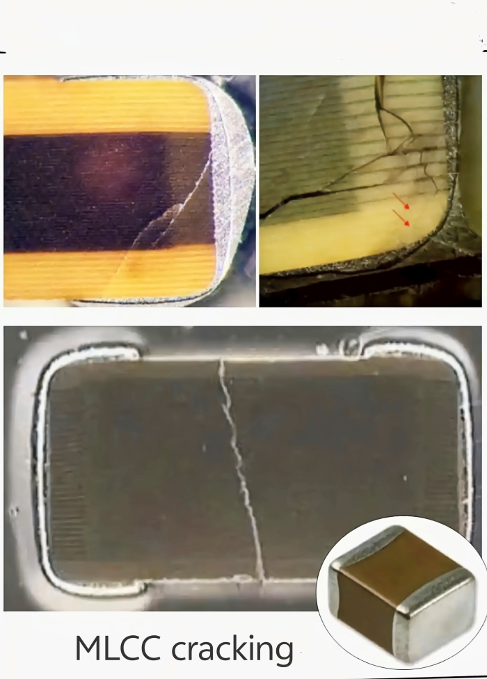
MLCC Cracking
• Cracking is the most typical mechanical failure mode for MLCCs due to the brittleness of their ceramic dielectric. Failure manifests as decreased insulation resistance, increased leakage current, and, in severe cases, short circuits leading to burnout. Core causes fall into three main categories: Temperature shock: Rapid thermal cycling during soldering (e.g., excessive peak temperatures followed by rapid cooling in reflow processes) or sudden environmental temperature changes like winter startup of outdoor equipment can cause cracking. Design flaws: Capacitor placement near PCB edges or stress points without adequate stress relief space also predisposes components to failure.
• Key methods for identifying MLCC cracking include: • Visual inspection with a 10-20x optical microscope, where cracks typically manifest as fine fissures along the top/bottom edges or through-side gaps, accompanied by ceramic powder shedding in severe cases; • Electrical testing: Measure leakage current with an insulation resistance tester. Cracked capacitors exhibit leakage current surging from normal nA levels to μA or even mA levels. Stress sources can be traced by reviewing assembly process records and simulating installation scenarios to test stress conditions on capacitors during PCB bending. Preventive measures require targeted strategies: Select MLCCs with flexible terminals, such as Murata's GRM series, to reduce mechanical stress transmission. During PCB design, position capacitors away from board edges and screw holes with a minimum clearance of 2mm. Employ a gradient-heating reflow profile during soldering to ensure peak temperatures do not exceed the dielectric's tolerance limit (e.g., ≤260°C for X7R dielectric).
DC Bias Capacity Loss
• Abnormal capacitance decay under DC bias is a common issue in nF ceramic capacitors, degrading filtering and decoupling performance (e.g., increased power supply ripple). The decay severity varies significantly across different dielectric materials. The core cause lies in the polarization characteristics of ceramic dielectric materials being affected by DC electric fields. Higher bias voltages result in more pronounced suppression of electric domain polarization, leading to more severe capacitance decay—X5R/X7R dielectrics exhibit significant decay (e.g., a 100nF X7R capacitor decays by 30%-50% under 10V bias), while C0G (NP0) materials remain virtually unaffected (≤1% attenuation). Additionally, smaller capacitance values and more compact nF-level packages exhibit more pronounced bias-induced attenuation.
• You can use two main methods to fix this problem. First, use an LCR meter that can apply bias voltage. Measure capacitance with no bias and with the actual operating bias. Then compare how much the capacitance drops. For example, a 100 nF X7R capacitor in a 12V circuit that loses more than 40% capacitance is considered failed. Second, build a test circuit with the real operating voltage. Measure the filtered ripple with an oscilloscope. If the ripple is higher than allowed and the power supply is fine, the capacitor has failed.Preventive measures require targeted strategies: prioritize C0G dielectric materials for precision applications, and select X7R capacitors with optimized bias characteristics for general-purpose scenarios (e.g., Yageo CC0805X7R104K250NT). Design with capacitance redundancy (e.g., select a 150nF X7R capacitor for 100nF effective capacity) to compensate for degradation.
Soldering Stress Failures
• Thermal stress, mechanical stress, and solder joint defects during soldering can cause nF capacitor failures, manifesting as immediate short circuits, open circuits, or intermittent failures during use. Such failures account for 20%-30% of all nF capacitor failures. Core causes include three aspects: Thermal stress arises from abnormal reflow soldering temperature profiles (e.g., heating rates >3℃/s, peak temperature dwell time >10s), causing delamination between the capacitor's internal electrodes and dielectric. Mechanical stress arises from manual soldering, where the soldering iron applies force to the capacitor body, or from pulling forces during PCB movement before cooling (due to differing thermal expansion coefficients between capacitors and PCBs). Solder joint defects stem from pad designs that are too small (<80% of the capacitor lead width) or insufficient solder volume, leading to joint cracking and subsequent poor contact.
• Three approaches can identify soldering failures: - Visual inspection with a magnifying glass: Cracks, voids, or separation between leads and pads indicate potential issues. - Thermal cycling test: Subject samples to 10 cycles between -40°C and +85°C. Capacitance drop or open circuits confirm thermal stress-induced internal failure. - Process verification: Review reflow soldering curve records and manual soldering operation standards to trace manufacturing defects. Preventive measures require targeted strategies: Establish optimized reflow profiles (e.g., X7R capacitors require 2℃/s ramp rate, 245℃±5℃ peak temperature, and 5-second dwell); ensure soldering irons contact only pads during manual soldering; match pad dimensions to capacitor leads (e.g., 0805 package pads: 1.8mm length, 1.2mm width).
EMC test failures caused by incorrect nF values
• nF capacitors are core components in EMC design. Incorrect capacitance selection or excessive deviation from rated values can easily cause EMI (electromagnetic interference) to exceed standards. This is commonly seen in power filtering and interface anti-interference scenarios, manifesting as failures in radiated or conducted disturbance tests. Core causes fall into three main categories: First, incorrect capacitance selection—e.g., using a 10nF decoupling capacitor when 100nF is required—results in incomplete high-frequency interference filtering. Second, tolerance exceeding specifications—e.g., using ±20% tolerance capacitors where ±10% is required—leads to insufficient filtering capability at low capacitance levels. Third, aging-induced capacitance decay, such as X5R capacitors experiencing over 20% capacitance loss after prolonged use, resulting in degraded EMC performance. A typical case involves a 22nF capacitor mistakenly installed as 2.2nF in a USB interface EMI suppression circuit, causing conducted emissions exceeding limits in the 10MHz-100MHz band.
• Three key methods can address this issue: First, capacitance verification—measure actual capacitance using a high-precision LCR meter (at 1kHz/1MHz test frequencies) and compare against design values. Deviations exceeding tolerance limits (e.g., 85nF measured for a 100nF ±10% design) indicate failure. Second, perform replacement verification by substituting the suspected faulty capacitor with a known-good, precisely calibrated capacitor of identical specifications. If EMC compliance is restored upon retesting, the capacitance issue is confirmed. Third, conduct spectrum analysis using a spectrum analyzer to pinpoint the interference frequency band. Combine this with capacitive reactance formulas to calculate the theoretical required capacitance and determine if the existing capacitor matches. Use specific steps to prevent problems. Choose precision capacitors with ±5% tolerance for important EMC paths. Check capacitance by sampling at least 3% during bulk buying to avoid batch tolerance problems. Use dielectrics like X7R or C0G that age slowly in hot or humid places to prevent capacitance loss over time.
Standard Value Systems (E-Series)
The E-Series is a standard capacitance system for electronic components established by the International Electrotechnical Commission (IEC). Its core function is to "divide capacitance specifications geometrically," covering a wide capacitance range while reducing redundant specifications, thereby lowering production, selection, and inventory costs. As the core category in the intermediate capacitance range, nF-level capacitors strictly adhere to E-Series specifications. Mastering the E-Series rules is fundamental to precise selection.
E6 / E12 / E24 Overview
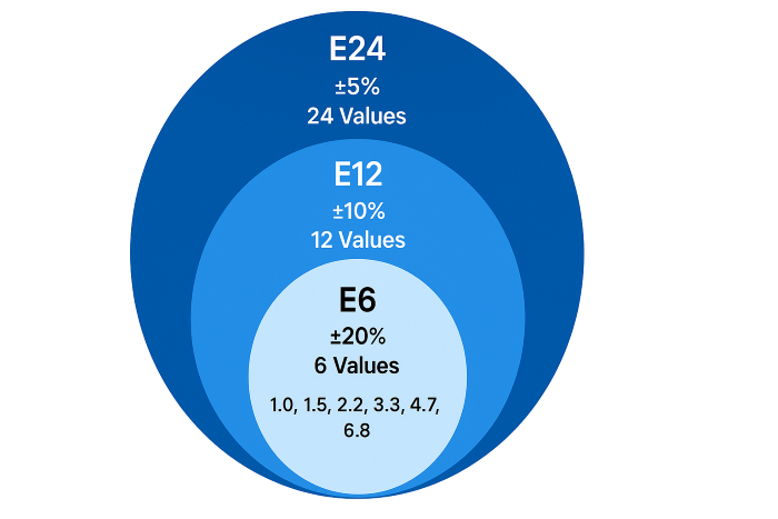
The E-series is subdivided into multiple sub-series based on "tolerance grades." Among these, E6, E12, and E24 are the three most commonly used series for nF capacitors. Stricter tolerances result in more specifications and higher precision requirements for application scenarios. The core differences between them are as follows:
• E6 Series: Tolerance grade ±20% (most lenient). Features only six base specifications across the entire range, increasing in geometric progression by 10^(1/6). Its core advantages are minimal specifications and extremely low cost, making it suitable for general-purpose applications with low capacitance precision requirements (e.g., standard filtering, bypassing). Base specifications: 1.0, 1.5, 2.2, 3.3, 4.7, 6.8 (units scalable to nF, μF, etc., requiring confirmation within the capacitance range).
• E12 Series: Tolerance grade ±10%, 12 base specifications increasing by 1/12th of 10. The mainstream choice for nF capacitors in consumer electronics is balancing precision and cost. Base specifications: 1.0, 1.2, 1.5, 1.8, 2.2, 2.7, 3.3, 3.9, 4.7, 5.6, 6.8, 8.2 (supports capacitance scaling).
Series Selection Logic: Prioritize series matching based on tolerance requirements—cost-sensitive scenarios select E6, general-purpose scenarios select E12, precision scenarios select E24. If a specific value is unavailable in a lower-precision series (e.g., 3.0nF), upgrade to a higher-precision series (E24) for selection.
Typical nF ranges
Common capacitance values for nF-level capacitors range from 0.1nF to 1000nF (1μF). Derive typical specifications across E-series within this range using the "capacitance scaling rule" (base value × 10^N, where N is an integer). Core specifications and matching applications are as follows:
General NF Specifications (Primarily E12 Series)
The E12 series, with its ±10% tolerance, suits most applications and is the primary nF capacitor specification. Typical nF values and applications:
• 0.1nF (100pF), 0.12nF, 0.15nF: High-frequency bypassing, e.g., RF module power supply filtering. Corresponding E12 base values: 1.0, 1.2, 1.5×10^-1.
• 1nF, 1.2nF, 1.5nF, 2.2nF: Mid-to-high frequency coupling/filtering, e.g., audio preamp circuit coupling, corresponding to E12 base specifications 1.0–2.2×10^0.
•10nF, 12nF, 15nF, 22nF, 33nF, 47nF: General-purpose filtering/decoupling, such as noise suppression for microcontroller I/O ports, corresponding to E12 fundamental specifications 1.0-4.7×10^1.
•100nF (0.1μF), 120nF, 150nF, 220nF, 470nF: Core specifications for power decoupling, such as filtering near chip power pins, corresponding to E12 base specifications 1.0–4.7×10^2.
Cost-Sensitive nF Specifications (E6 Series)
The E6 series offers only six specifications, covering core nF-level requirements for small appliances, simple circuits, and similar applications. Typical specifications: 1nF, 1.5nF, 2.2nF, 3.3nF, 4.7nF, 6.8nF, 10nF, 15nF, 22nF, 33nF, 47nF, 68nF, 100nF, etc. (Scaled by multiplying base value by 10^N). For example, in small led driver circuits, prioritize E6 Series 47nF or 100nF for filter capacitors.
The E24 series supplements intermediate values not covered by E12, meeting precision application requirements. Typical nF values: 0.33nF, 0.47nF, 0.68nF, 3.0nF, 4.3nF, 5.1nF, 6.2nF, 7.5nF, 9.1nF, etc. For example, high-frequency oscillation circuits require a 3.0nF capacitor (unique to E24), while precision RC delay circuits require a 4.3nF capacitor—both necessitating the E24 series.
Practical Examples: AC Impedance & Frequency Behavior
AC impedance is the core manifestation of the nF capacitor frequency characteristics. Its fundamental component, "capacitive reactance," directly determines the capacitor's role in circuits at different frequencies (e.g., filtering, coupling, decoupling). This section uses formula analysis and calculation examples at typical frequency points to visually demonstrate how nF capacitor impedance varies with frequency, providing data support for scenario-based selection.
Capacitive Reactance Formula
The primary impedance component of nF capacitors in AC circuits is "capacitive reactance" (Xc), which represents the capacitor's resistance to alternating current signals. Its magnitude is inversely proportional to both signal frequency and capacitance value. The core formula and interpretation are as follows:
Formula parameter explanation:
Xc: Capacitive reactance, measured in ohms (Ω). Higher values indicate stronger impedance to signals at that frequency. π: The mathematical constant pi, approximately 3.14.
f: AC signal frequency, measured in hertz (Hz). Common units also include kilohertz (kHz, 1kHz = 10³Hz) and megahertz (MHz, 1MHz = 10⁶Hz);
C: Capacitance, measured in farads (F). When calculating, convert nF to farads (1 nF = 10⁻⁹ F).
• Key principles: At a fixed frequency, higher capacitance yields lower capacitive reactance (e.g., a 100nF capacitor exhibits significantly lower capacitive reactance at 1kHz than a 1nF capacitor). At a fixed capacitance, higher frequency results in lower capacitive reactance (e.g., a 10nF capacitor's capacitive reactance at 1MHz is only 1/1000th of its value at 1kHz). These principles form the core basis for selecting nF capacitors in specific applications. (e.g., selecting a smaller capacitance in high-frequency scenarios can also achieve low-impedance filtering).
• Unit Conversion Notes:
Unify units before calculation. For example, to calculate "capacitive reactance of a 10nF capacitor at 1kHz," first convert C=10nF to 10×10⁻⁹F=10⁻⁸F and f=1kHz to 10³Hz before substituting into the formula.
Example Frequency Points (1kHz – 1MHz)
Three commonly used nF capacitance values in circuits (1nF, 10nF, 100nF, covering E12 standard specifications) are selected. Their capacitive reactance at four typical frequency points (1kHz, 10kHz, 100kHz, 1MHz) is calculated to visually demonstrate the "capacitance-frequency-reactance" relationship. The results are analyzed to explain practical application logic.
The results calculated using the capacitive reactance formula for each combination are shown in the table below. The calculation process is illustrated using "10nF at 1kHz" as an example: Xc=1/(2×3.14×10³Hz×10×10⁻⁹F)≈15915Ω≈15.9kΩ.
|
Capacitance |
1kHz (Low Frequency) |
10kHz (Mid-Low Frequency) |
100kHz (Mid-High Frequency) |
1MHz (High Frequency) |
|
1nF |
≈159.2kΩ |
≈15.9kΩ |
≈1.59kΩ |
≈159Ω |
|
10nF |
≈15.9kΩ |
≈1.59kΩ |
≈159Ω |
≈15.9Ω |
|
100nF |
≈1.59kΩ |
≈159Ω |
≈15.9Ω |
≈1.59Ω |
Based on the table data, the selection logic for nF capacitors across different frequency scenarios can be distilled, aligning with the previously mentioned applications such as "filtering and decoupling":
• Low-frequency scenarios (1kHz, e.g., audio signals): 1nF capacitance reactance reaches 159.2kΩ, severely impeding low-frequency signals and failing to achieve filtering; 100nF capacitance reactance is only 1.59kΩ, effectively filtering low-frequency ripple. Therefore, 100nF capacitors should be prioritized for power filtering in audio circuits over smaller nF capacitors.
• Mid-to-high frequency scenarios (100kHz, e.g., microcontroller clock signals): 10nF capacitance offers 159Ω reactance, while 100nF provides 15.9Ω reactance—both achieve decoupling. However, 10nF capacitors feature a smaller size, lower cost, and reduced parasitic inductance. Thus, high-frequency decoupling often selects 10nF over larger capacitors to balance performance and cost.
• High-frequency scenarios (1MHz, e.g., RF modules): 1nF capacitance with 159Ω reactance meets high-frequency bypass and impedance matching requirements, ensuring stable signal transmission in high-speed RF circuits. While 100nF offers lower reactance at 1.59Ω, the parasitic inductance of larger 100nF packages may cause the self-resonant frequency (SRF) to fall below 1MHz, resulting in inductive behavior. Therefore, smaller nF capacitors (e.g., 1nF, 10nF) are preferred for high-frequency applications.
• Cross-frequency adaptation: 100nF exhibits reactance dropping from 1.59kΩ to 1.59Ω across 1kHz-1MHz, covering mid-low to high frequencies. This makes it a "universal decoupling capacitor" (e.g., for chip power pins), suitable for filtering noise with multiple frequency components.
Practical Summary: The "frequency-impedance" characteristics of nF capacitors dictate the selection principle of "small capacitance for high frequencies, large capacitance for low frequencies." In actual design, one must consider the target signal frequency and use the capacitive reactance formula for quick estimation to avoid blindly selecting large-capacitance capacitors that degrade high-frequency performance.
Conclusion
Nanofarad capacitors are the main middle-size capacitors between picofarads and microfarads. They are essential for filtering, decoupling, coupling, timing control, and other uses. They are flexible, easy to convert, and made with mature processes.Mastering the conversion rules between nF, pF, and μF, understanding labeling methods like three-digit codes, and matching parameters like voltage rating, dielectric material, and temperature coefficient to application requirements are key. Additionally, proper procurement substitution and failure prevention are essential. From everyday consumer electronics to industrial precision equipment, the proper selection and application of nF capacitors are core elements in ensuring stable and reliable circuit operation.