Metal Film vs Carbon Film Resistors: Which to Choose?
| Table of Contents |
Quick Takeaways: Which One Should You Use?
Metal Film Resistors (MFR) and Carbon Film Resistors (CFR) are the two most widely used types of general-purpose resistors in electronic circuits. The core considerations for selecting either type always revolve around three key dimensions: accuracy requirements, noise control, and cost constraints. The following key takeaways will help you quickly identify the optimal choice for different scenarios, providing direct reference for circuit design, component procurement, or technical implementation.
Three Key Takeaways (Accuracy, Noise, Cost)
Metal Film Resistors (MFR) are ideal for precision circuits demanding strict accuracy, stability, and low noise. Carbon Film Resistors (CFR) offer a cost-effective solution for general-purpose applications and budget-sensitive projects. This fundamental distinction manifests across three critical dimensions: accuracy control, noise performance, and cost efficiency.
• Prioritize MFR for high precision and long-term stability: Resistance tolerance as low as ±0.1%, temperature coefficient ±10 to ± 50ppm/°C, suitable for precision measurement, industrial control, and similar applications.
• For low-noise requirements, prioritize MFR: Current noise < 0.1 μV/ √Hz with minimal signal interference, suitable for audio
equipment (including tube amps), medical instruments, and similar applications.
• Cost control is paramount? Opt for CFR: Its unit price at volume is only 1/3 to 1/5 that of MFR, making it suitable for consumer electronics and standard power supply circuits.
• For general-purpose applications without specific requirements, CFR is recommended: It meets the cost-effective needs of auxiliary circuits like simple switches and indicator light drivers.
Basics: What Are CFR and MFR Resistors?
To select the right resistor, you must first understand the fundamental differences between these two types, which requires a basic grasp of their manufacturing principles, structural characteristics, and core properties. Below, we break down the key information for carbon film resistors and metal film resistors, clarifying their core distinctions through comparison.
What Is a Carbon Film Resistor (CFR)?
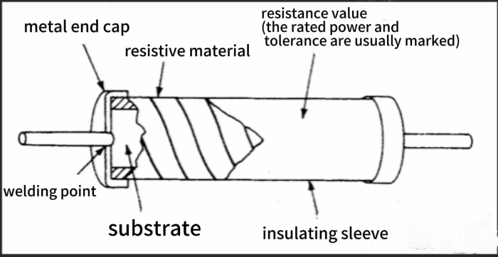
A carbon film resistor (CFR) is created by uniformly depositing carbon-based material onto an insulating ceramic rod via vacuum deposition to form a conductive film. The length and cross-sectional area of this film are then precisely controlled by mechanically etching spiral grooves, thereby achieving accurate resistance values. This manufacturing process is mature and cost-effective. However, due to limitations in carbon film material properties and slot precision, its resistance tolerance is typically wide (commonly ±5% to ±10%) and exhibits relatively high current noise levels. Nevertheless, its strong price‑performance ratio makes it a mainstream choice in general-purpose circuits.
What Is a Metal Film Resistor (MFR)?
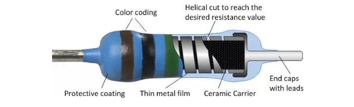
Metal film resistors (MFR) use a ceramic rod as the substrate. A thin metal or alloy film (such as a nickel-chromium alloy) is deposited on its surface via sputtering or evaporation to form the conductive layer. To achieve precise resistance values, the conductive film is etched with finer spiral grooves. Combined with the excellent conductive stability of the metal film itself, this provides core advantages of high precision (tolerance as low as ±0.1%), low current (excess) noise, and superior temperature coefficient (TCR). It maintains stable resistance values across a wide temperature range, making it suitable for precision circuit applications.
What is the difference between CFR and MFR resistors?
To clearly illustrate the key differences between carbon film resistors (CFR) and metal film resistors (MFR), the table below summarizes dimensions across materials, performance, and cost, helping you quickly grasp the core selection criteria.
|
Parameters |
Carbon Film Resistor (CFR) |
Metal Film Resistor (MFR) |
|
Core Material |
Carbon-based film |
Metal/Alloy Film (e.g., Nickel-Chromium) |
|
Accuracy |
Low |
High |
|
Resistance tolerance |
±5% to ±10% |
±0.1% to ±1% |
|
Temperature Coefficient (TCR) |
Poor (±100 to ±300 ppm/°C) |
Excellent (±10 to ±50 ppm/°C) |
|
Current Noise |
Higher (0.5–1 μV/√Hz) |
Low (<0.1 μV/√Hz) |
|
Price |
Low (bulk unit price approximately 1/3 to 1/5 of metal film resistors ) |
Higher |
Construction and Manufacturing Differences
Structural design and manufacturing processes are fundamental to determining a resistor's core performance. Differences in these aspects directly affect key metrics, such as precision and noise. Below, we will dissect the structural composition and manufacturing processes of both resistor types, focusing on the impact of spiral grooves.
Construction of Carbon Film Resistors
The core structure of a carbon film resistor consists of an "insulating substrate-conductive film-electrode leads." The manufacturing process can be summarized in four steps: First, a high-purity ceramic rod is selected as the insulating substrate (ensuring high-temperature resistance and insulation properties). Next, a carbon-graphite composite is deposited onto the ceramic rod surface by vacuum evaporation, forming a uniformly thick, conductive carbon film. The critical step is spiral grooving — using precision mechanical tools to etch spiral grooves into the carbon film. Resistance is adjusted by altering groove density (i.e., effective length of the conductive film). Lower groove density and wider groove spacing result in lower resistance. Finally, metal caps are pressed onto both ends of the ceramic rod, and leads are soldered to complete the electrode connection. The impact from structure to performance can be summarized as follows: Coarser spiral grooves and fewer turns allow for greater adjustment of the conductive path, but with limited precision. Additionally, the carbon-based film itself has average thermal conductivity and mechanical strength, and grooving further reduces the effective cross-sectional area and heat dissipation area. Simultaneously, the precision of mechanical grooving is limited, and fluctuations in film thickness and density are common, typically resulting in resistance tolerances of only ±5% to ±10%, making it generally not suitable for high-precision circuits.
• Impact on parasitic inductance: Coarse spiral grooves and fewer turns result in weaker inductive effects from the equivalent spiral conductor, leading to relatively low parasitic inductance.
• Impact on noise: Carbon film inherently lacks uniformity. Mechanical grooving often creates irregular burrs at edges, which can generate signal interference when current flows, resulting in higher current noise.
• Impact on power handling/heat dissipation: Carbon-based films exhibit average thermal conductivity. Grooving reduces the effective heat dissipation area of the conductive layer, resulting in moderate power ratings (typically 1/4W to 2W) and limited thermal efficiency.
Construction of Metal Film Resistors
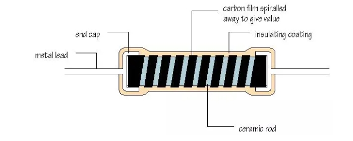
Metal film resistors share a similar structure to carbon film resistors but utilize superior materials and manufacturing precision. The substrate remains a ceramic rod, but the conductive layer is replaced with alloys such as nickel-chromium or tin-palladium, deposited via magnetron sputtering (enabling denser, more uniform films with nanometer-level thickness precision). Spiral grooves are created using laser etching, resulting in higher groove density, narrower groove widths, and smoother edges. Precise control over groove pitch and depth enables high-accuracy resistance adjustment. The impact from structure to performance can be summarized as follows: The combination of dense, uniform alloy film with laser-etched precision grooves ensures high consistency in the conductive path and smooth groove edges, resulting in significantly superior resistance accuracy and long-term stability compared to carbon film. Although finer grooves and increased turn counts introduce some inductive effects, these can be compensated for through optimized groove profiles. Additionally, the alloy film's superior thermal conductivity, coupled with the uniform heat dissipation design of the grooves, delivers outstanding resistance stability at high temperatures.
• Impact on parasitic inductance: Finer grooves and increased turns yield slightly higher inductance effects from the equivalent helical conductor compared to carbon films. However, shallow groove design and groove shape optimization render this impact negligible in low-frequency and most mid-frequency applications.
• Impact on noise: The alloy film exhibits inherent uniformity, and laser-etched grooves feature smooth edges without burrs. This minimizes signal interference during current flow, resulting in extremely low current noise (<0.1 μV/ √Hz).
• Impact on Power/Heat Dissipation: The alloy film exhibits higher thermal conductivity than carbon film. Combined with the uniform heat dissipation design achieved through grooving, it delivers superior power handling (up to 1/2W~5W), high heat dissipation efficiency, and more stable performance at elevated temperatures.
Key Performance Comparison: Accuracy, Temperature, Noise
Differences in structure and manufacturing processes ultimately manifest in core performance parameters such as resistance accuracy, temperature adaptability, and noise levels. The following comparison focuses on three critical dimensions most relevant to circuit design, clarifying the performance boundaries and applicable scenarios for both resistor types.
Resistance Tolerance and Long-Term Stability
Resistance accuracy determines circuit parameter control precision: Carbon film resistors are constrained by film uniformity and mechanical grooving, typically offering tolerances of ±5% to ±10% (reaching ±20% at the lower end). Metal film resistors leverage alloy films and laser grooving technology to achieve tolerances as low as ±1%, with high-precision models reaching ±0.1% to ±0.01%.Regarding long-term stability, carbon film resistors are prone to oxidation and flaking due to temperature and humidity, with resistance drift exceeding 5% after five years. Metal film resistors feature highly stable alloy layers that exhibit drift <1%, making them suitable for long-term operation in industrial equipment and precision instruments.
Temperature Coefficient (TCR) and Voltage Coefficient (VCR)
Temperature Coefficient (TCR, units ppm/°C; lower absolute values indicate greater stability): Carbon film TCR ranges from ± 100 to ± 300 ppm/°C, exhibiting significant resistance fluctuations across the wide temperature range (- 40 °C to 125 °C), which impacts precision circuit accuracy. Metal film TCR is only ±10 to ±50 ppm/ °C, offering excellent stability across a wide temperature range and making it the preferred choice for precision circuits. Regarding Voltage Coefficient (VCR), carbon film VCR ranges from 10 to 50 ppm/V and is prone to nonlinearity at high voltages. Metal film VCR is <10 ppm/V, delivering superior linearity in high-voltage applications.
Noise Performance and Signal Integrity
Resistor noise directly impacts signal purity, primarily comprising thermal noise and current noise: Carbon film exhibits higher current noise (0.5~1 μ V/ √Hz) due to uneven carbon particles and slot burrs, easily interfering with weak signals; Metal films utilize uniform alloy layers and laser precision grooving, achieving extremely low current noise (<0.1 μ V/ √Hz) to ensure signal integrity. They are the preferred choice for low-noise amplifiers, audio equipment, medical instruments, and similar applications.
Parameter vs CFR/MFR Advantages Comparison
To more intuitively quantify the performance differences between the two resistor types and clearly illustrate their relative strengths across various parameters, the table below outlines selection guidance based on core performance metrics and practical application scenarios, facilitating rapid decision-making.
|
Performance Parameters |
Carbon Film Resistor (CFR) |
Metal Film Resistor (MFR) |
Application Scenario Guidance |
|
Resistance Accuracy |
Poor ( ±5% to ±10%) |
High ( ±0.1% to ±1%) |
Choose MFR for precision control, CFR for general applications |
|
Long-Term Stability |
Poor (drift >5%) |
Excellent (drift <1%) |
Prioritize MFR for long-term operational equipment |
|
Temperature Coefficient (TCR) |
Poor ( ±100 to ± 300 ppm/°C) |
Excellent ( ± 10~ ± 50 ppm/°C) |
Select MFR for wide-temperature or precision measurement |
|
Voltage Coefficient (VCR) |
Poor (10 – 50 ppm/V) |
Excellent (<10 ppm/V) |
High-voltage circuits should prioritize MFR |
|
Noise Performance |
Poor (0.5 – 1 μV/ √Hz) |
Excellent (<0.1 μV/ √Hz) |
Select MFR for low-noise signal processing |
What are the disadvantages of carbon film resistors?
• High noise: Elevated current noise levels can cause signal distortion or interference in audio equipment and weak signal amplifiers, compromising output quality.
• Wide resistance tolerance: Tolerances of ± 5% to ± 10% fail to meet the precision requirements of critical circuits, introducing significant errors in voltage reference circuits and precision measurement instruments.
• High temperature coefficient: Large TCR values cause noticeable resistance fluctuations in high/low-temperature environments, leading to unstable circuit performance in outdoor equipment or industrial high-temperature applications.
• Poor long-term stability: Carbon film is prone to oxidation, and its layer adhesion is relatively low. After prolonged use, resistance drift exceeds 5%, making it unsuitable for applications that demand extremely high long-term reliability, such as medical equipment and aerospace.
Application Scenarios: Where to Use Which Type?
Considering the performance differences outlined above, resistor selection must adhere to the core logic of "scenario requirements - performance matching - cost balance." The following outlines the applicable boundaries and selection criteria for both resistor types across different industries and circuit types.
General and Appliance Use Cases (CFR First Choice)
General electronics and appliance applications primarily prioritize "basic circuit functionality + cost control," with no stringent requirements for resistance accuracy or noise levels. Carbon film resistors excel here due to their high cost-performance ratio. Typical applications include: voltage divider resistors in power circuits (e.g., output voltage sampling in standard linear power supplies), current-limiting resistors in load circuits (e.g., LED indicator drivers, small relay coil current limiting), and appliance control boards (e.g., washing machine inlet valve control, air conditioner fan speed regulation auxiliary circuits). For example, a washing machine control board, circuits for button signal detection, and indicator status display only require resistors to perform basic signal switching or current limiting. Carbon film resistors with ±10% tolerance can meet these requirements while costing only one-third to one-fifth as much as metal film resistors with the same specifications, significantly reducing total production costs for mass manufacturing. If the circuit later needs to be upgraded to lower noise (e.g., adding a simple audio prompt function), replacing a carbon film resistor with a metal film resistor in this low-frequency auxiliary circuit is safe and can improve signal purity without reworking the board.
Precision Measurement and Audio Circuits (MFR Preferred)
Precision measurement and audio processing applications demand stringent "parameter accuracy" and "signal purity." The high precision and low noise characteristics of metal film resistors make them the core selection criterion. Typical applications include: operational amplifier feedback resistors (directly impacting gain accuracy, requiring ± 0.1% to ± 1% tolerance to ensure stable amplification), precision reference circuits (e.g., sampling resistors in voltage reference sources, where low TCR ensures reference voltage error <0.1% over wide temperatures), bridge measurement circuits (e.g., bridge arm resistors in strain gauge load cells, where high-precision matching minimizes measurement errors), and audio signal paths (e.g., signal divider resistors in headphone amplifiers, where low noise prevents audio distortion). For instance, in medical blood pressure monitors, the pressure sensor signal amplification circuit requires metal film resistors. Their ±0.5% tolerance and low-noise characteristics ensure blood pressure measurement errors are controlled within ±1 mmHg.
Considerations for High-Frequency and Pulse Applications
Both resistor types employ spiral grooved structures. The "spiral conductors" formed by grooving introduce parasitic inductance (typically 5~50nH). In high-frequency (>1 MHz) or pulse circuits, this parasitic inductance forms an RL series circuit with the resistor. This causes the actual impedance to increase with frequency, deviating from the design value. For high-frequency applications, prioritize resistor models with sparse grooves (lower parasitic inductance) or adjust power ratings based on frequency range (higher-power resistors feature shallower grooves and slightly lower parasitic inductance). When frequencies exceed 100MHz, the parasitic inductance of both resistor types becomes significant. Replace them with metal oxide film resistors without helical grooves or chip film resistors to minimize high-frequency impedance deviation. Additionally, in pulse circuits, parasitic inductance may resonate with circuit capacitance, generating voltage spikes. Pair with RC snubber circuits to suppress interference.
Application Scenario Selection Matrix
To clarify selection logic and facilitate quick reference across different scenarios, the matrix below integrates core application scenarios, recommended resistor types, suggested tolerances, and key matching criteria. It serves as a direct, quick-reference guide for selection.
|
Application Scenario |
Recommended Resistor Type |
Recommended Resistance Tolerance |
Core Requirement Matching Points |
|
Home Appliance Control Boards (Washing Machines, Refrigerators) |
Carbon Film Resistor (CFR) |
±5% to ± 10% |
Cost-sensitive, requiring only basic current limiting/voltage division functionality |
|
Standard power supply voltage division/current limiting |
Carbon Film Resistor (CFR) |
±5% to ±10% |
Low precision requirements, prioritizing bulk purchase cost |
|
Operational amplifier feedback circuit |
Metal Film Resistor (MFR) |
±0.1% to ±1% |
High precision ensures stable amplification gain |
|
Precision measuring instruments (blood pressure monitors, multimeters) |
Metal Film Resistor (MFR) |
±0.1% to ±0.5% |
Low noise, low TCR reduces measurement errors |
|
Audio equipment (headphone amplifiers, audio systems) |
Metal Film Resistor (MFR) |
±0.5% to ±1% |
Low noise prevents sound distortion and ensures signal purity |
|
High-frequency circuits (1~100MHz) |
Metal Film Resistor (MFR, Low Parasitic Inductance Type) |
±1% to ±5% |
Finer grooves result in relatively lower parasitic inductance |
|
LED drivers (indicator lights, general lighting) |
Carbon Film Resistor (CFR) |
±5% to ±10% |
Requires only basic current limiting functionality; cost-priority solution for volume applications |
Replacement and Compatibility: Can You Swap CFR and MFR?
The core of resistor replacement lies in "parameter matching" and "application suitability." Bidirectional replacement between metal film and carbon film resistors is not universally feasible and should be evaluated based on circuit requirements. Below is a directional analysis of replacement feasibility and key verification points.
Can I replace a carbon film resistor with a metal film resistor?
In most low-frequency (<1MHz) and standard functional circuits (e.g., home appliance controls, basic power supply voltage division), replacing a carbon film resistor with a metal film resistor of identical specifications is generally safe—this is especially true for non-critical paths like indicator current limiting or button signal detection. Metal film resistors' higher precision and lower noise characteristics may even enhance performance, such as reducing signal interference in simple audio auxiliary circuits. However, complete the following six checks before replacement to ensure parameter matching:
• Resistance consistency check: The replacement metal film resistor must have the same resistance value as the original carbon film resistor (e.g., 1k Ω for the original, 1k Ω for the new). The tolerance must fall within the circuit's permissible range.
• Tolerance Matching Check: Metal film tolerances are typically superior to carbon film. If the original circuit has no special precision requirements, a ±1% tolerance metal film resistor can directly replace a ±5% to ±10% carbon film resistor. If the circuit has precision constraints, ensure the new tolerance is no lower than the original requirement.
• Power Rating Verification: The rated power of the metal film resistor must be ≥ that of the original carbon film resistor (e.g., if the original is 1/4W, the new resistor must be at least 1/4W) to prevent burnout due to insufficient power.
• Withstand voltage compatibility check: Verify the rated withstand voltage of the resistor to ensure the metal film resistor's voltage rating is no lower than the original carbon film resistor, especially critical in high-voltage circuits.
• Size Compatibility Check: Ensure the package dimensions of the metal film resistor match those of the carbon film resistor (e.g., pin pitch and body length for through-hole resistors) to prevent installation failure or component interference due to mismatched dimensions.
• Temperature Range Matching: Confirm the metal film resistor's operating temperature range covers the original circuit's working conditions to prevent performance anomalies in low- or high-temperature environments.
Risks When Replacing Metal Film with Carbon Film
Reverse replacement of metal film resistors with carbon film resistors requires extreme caution and is not recommended for precision, low-noise, or critical functional circuits. Key risk scenarios and causes include:
• Precision measurement/control circuits: Carbon film resistors' ±5% to ±10% tolerance is significantly lower than metal film, causing deviations in critical parameters like voltage reference and amplification gain. For example, replacing resistors in multimeter sampling circuits drastically reduces measurement accuracy.
• Low-noise signal circuits: Carbon film's high current noise can interfere with audio amplifiers and sensor signal processing circuits, causing audio distortion or reduced signal-to-noise ratio in measurements.
• Current detection/feedback circuits: Carbon film's significant temperature drift ( ±100 to ±300 ppm/°C) causes resistance drift in motor control or power supply current feedback circuits during temperature changes, resulting in reduced control accuracy or erroneous circuit protection triggers.
• Long-term operational equipment: Carbon film resistors exhibit poor long-term stability. In industrial controllers, medical devices, and other applications that require sustained, reliable operation, resistance drift can easily cause equipment failures. Reverse replacement should be attempted only when the original circuit is a standard low-frequency auxiliary circuit with no precision/noise/stability requirements (e.g., indicator lamp current limiting), and when resistance values, power ratings, and other parameters are strictly matched.
How Do You Tell If a Resistor Is a Metal Film?
Rapidly distinguishing metal film resistors (MFR) from carbon film resistors (CFR) can be achieved through a three-step method: "Visual Inspection - Marking Verification - Simple Testing." Appearance and markings provide the most convenient preliminary judgment, while testing offers further validation. Detailed explanations by dimension follow:
Visual and Color Indicators
The resistor body color provides the most intuitive initial clue, though note that this isn't an absolute standard ( it varies by manufacturer). Key characteristics are compared below:
• Metal Film Resistors: Mainstream through-hole models typically feature blue bodies (e.g., common 1/4W, 1/2W through-hole resistors), while some high-precision models use gray or black. The body surface is generally smoother, with finer engraving lines (if present). Surface-mount metal film resistors are predominantly black-encapsulated with no distinct color specificity.

• Carbon Film Resistors: Traditional through-hole models predominantly feature brown, beige, or light gray casings with relatively rough surfaces. Some low-power variants exhibit shallow grooves, resulting in less pronounced surface texture. Surface-mount carbon film resistors are also predominantly black, making color-based differentiation from surface-mount metal film resistors challenging.
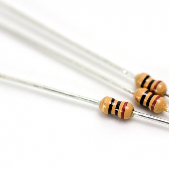
Special Note: Some manufacturers use custom color packaging. For example, military-grade carbon film resistors may be green. Therefore, color should only serve as a preliminary reference and must be verified alongside other characteristics.
Package Markings and Datasheet Check
Checking the datasheet via markings on the resistor package is the most accurate method for identifying resistor types. However, the approach for obtaining markings differs between through-hole and surface-mount resistors, requiring specific procedures. If you're working with leaded components, mastering the 2.2 k resistor color code and similar marking systems is essential for quick visual identification without a datasheet. The detailed process is as follows:
• Through-hole resistors: Directly query via body markings. Through-hole resistors typically bear key identifiers such as brand, model, or series name printed directly on the body. After recording these markings, use the manufacturer's official website or component databases(e.g., Digi-Key, Mouser, LCSC) to find the corresponding model. The datasheet's "Film Material" or "Technology Type" section will explicitly state "Carbon Film" or "Metal Film." Additionally, you can obtain core parameters such as power rating, resistance tolerance, temperature coefficient (TCR), and noise specifications, making the identification process relatively straightforward.
• Chip Resistors: Identification via Full Part Number The surface silkscreen markings on chip resistors (e.g., "102" representing 1k Ω ) indicate only the resistance value and do not include material type information. This makes it impossible to directly determine whether the resistor is carbon film, metal film, or thick film. Accurate identification requires the full part number, which can be obtained from purchase labels, batch packaging, BOM lists, or supply chain management systems. After retrieving the datasheet via the part number, the "Technical Type" section confirms the category — surface-mount metal film resistors typically fall under the 'Thin Film Precision' series. Common models include Vishay CRCW series, Yageo RC series (available in 0805, 1206, etc.), and MELF (Micro Electronic Lead Frame) packages (cylindrical surface-mount), which are also preferred for high-frequency, low-noise applications. Note: Most standard surface-mount resistors on the market are actually thick-film resistors, not carbon film or metal film resistors.
Simple Tests: Tolerance and Temperature Drift
If labeling or datasheets are unavailable, simple tests with a multimeter can aid identification, suitable for rapid on-site verification:
• Resistance Accuracy Test: Measure the actual resistance value using a high-precision multimeter (accuracy ≥ 0.1%) and compare it to the nominal value. If the deviation between the actual and nominal values is ≤ 1%, it is likely a metal film resistor. If the deviation falls within 5% – 10% and the color is brown/beige, it is more likely a carbon film resistor. Example: Nominal 1k Ω resistor, measured 998 Ω (0.2% deviation) → Metal film; Measured 920 Ω (8% deviation) → Carbon film.
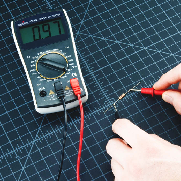
• Simplified Temperature Drift Test: Gently heat the resistor for 10 seconds using a heat gun (low setting, 50 – 80 ° C) while observing the multimeter reading. Metal film resistors typically show <0.5% change (e.g., 1k Ω → 1003 Ω ); carbon film resistors may exceed 1% change (e.g., 1k Ω → 1015 Ω ). Note: Strictly control heating temperature to prevent damage.
Cost, Availability, and Brand Options with Unikeyic
In engineering practice, cost control, supply stability, and brand reliability are the three core dimensions that require careful balancing during mass production — particularly when choosing between carbon film resistors (CFR) and metal film resistors (MFR), which directly affect overall BOM costs and project advancement efficiency. Leveraging Unikeyic's supply chain advantages, this guide provides engineers and procurement professionals with a comprehensive selection reference across four dimensions: cost variance analysis, bulk purchasing strategies, mainstream brand selection, and rapid search methods.
Cost Differences and Bulk Purchasing Tips
In high-volume production scenarios, the unit price difference between CFR (carbon film resistors) and MFR (metal film resistors) directly impacts the overall cost structure. CFR typically offers lower manufacturing costs and is suitable for functional circuits with less stringent requirements for resistance accuracy and temperature drift, such as LED current limiting, power supply shunt voltage division, and basic signal blocking. In contrast, MFRs deliver lower noise, more stable temperature coefficients, and tighter resistance tolerances. They offer distinct advantages in high-precision analog front ends, ADC/DAC inputs, amplifier bias circuits, and timing-sensitive modules.
In engineering practice, it is recommended to prioritize MFRs at critical nodes while using CFRs at non-critical or high-volume distributed nodes to control overall costs. This "performance-first + cost-tiering" strategy balances reliability with BOM optimization, empirically reducing resistor costs by 10 – 30% while avoiding increased rework and debugging expenses.
Common CFR/MFR Brands and Series
When selecting resistors, brand and series equally determine long-term supply stability and performance consistency. The Unikeyic platform covers the global supply chain for mainstream semiconductors and passive components, including brands such as NXP, TI, ST, Microchip, ADI, and ON. It offers over 200,000+ in-stock items and 10,000,000+ part numbers, catering to diverse needs from R&D prototyping to mass production.
For the common CFR and MFR series, engineers should prioritize the following parameter combinations:
• Thin Film Process: Precision MFR series, suitable for signal chains.
• Thick Film Process: Mass-market, low-cost models for general-purpose applications.
• MELF Cylindrical Package: Stable performance in high-frequency, low-noise environments.
• High-power through-hole series (e.g., CFR-25): Enhanced thermal dissipation for power-intensive applications.
Centralized procurement through Unikeyic ensures component consistency while reducing multi-channel management costs and delivery risks.
How to Quickly Find the Right Resistors on Unikeyic
Unikeyic's intelligent filtering system enables engineers and procurement personnel to swiftly locate resistors matching requirements through clear parameter selection steps.
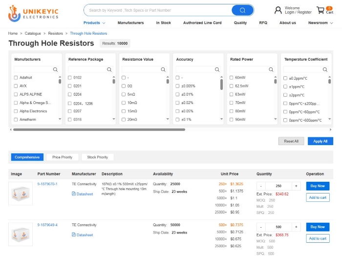
On the homepage, click "Products" to access the product categories. Select "Resistors " to view resistor classifications. Using the "Through Hole Resistors" interface as an example, you can select parameters at the top of the page based on your requirements (such as manufacturer, reference package, resistance value, and accuracy
, power rating, temperature coefficient, etc.) to view qualifying products and their unit prices.
Practical Tips for Design and BOM Specification
After finalizing CFR and MFR selection decisions, the standardization of schematic symbols and BOM entries directly affects procurement efficiency, production compatibility, and the control of substitution risk. Below are actionable methods covering specification rules and risk mitigation.
How to Specify CFR/MFR in Schematics and BOM
Schematics and BOMs must form a closed loop in which "design intent is clear and procurement basis is explicit," preventing misprocurement or performance mismatches caused by ambiguous descriptions. Specific guidelines are as follows:
1. Schematic Symbol Specifications
Resistor symbols must include combined "type-core parameter" information using the standardized format: [Type Abbreviation] + Resistance Value + Power Rating + Tolerance. This ensures that design intent is directly communicated to procurement and production. For a detailed breakdown of schematic representations, including the standard fixed resistor symbol, refer to our comprehensive guide on component symbols. For example:
• Metal film resistor annotation: MFR 1k Ω 1/4W ±1% (clearly identifies MFR type with complete core parameters)
• Carbon film resistor annotation: CFR 10k Ω 1/2W ±5% (distinguishes CFR type to avoid confusion with MFR)
Additionally, it is recommended to include "Critical Circuit Notes" in the schematic annotation field, such as "U1 feedback resistor (MFR), do not substitute with CFR," to reinforce selection constraints for critical components.
2. BOM Information Completeness Requirements
As the core document for procurement execution, the BOM must include four essential elements: "type identifier, specification parameters, brand recommendation, and material code." Each is indispensable. The type identifier must correspond to the schematic; specification parameters should detail critical metrics such as tolerance and temperature coefficient; and brand recommendations may indicate "preferred/alternative" to enhance supply chain flexibility. Example:
• Material Description: Resistor-MFR-1k Ω -1/4W- ±1%-TCR ± 50ppm/°C-Preferred NXP MF0204
• Avoid ambiguous descriptions: "Resistor 1k Ω " (lacks specified type and critical parameters, prone to incorrect procurement)
How to Allow Safe Substitutions
BOM entries must balance "design rigor" with "procurement flexibility." By clearly defining constraints such as "permitted substitution scope," "tolerance fluctuation limits," and "prohibited types," substitution risks can be significantly reduced. The core principle is: lock critical parameters while allowing flexibility for non-critical ones. Key writing points are as follows:
• Define substitution boundaries: Specify "Allowed Substitution Types" or "Prohibited Substitution Types," e.g., "Allow MFR substitution, prohibit CFR substitution";
• Allow sufficient tolerance range: For non-critical applications, specify upper tolerance limits, e.g., " ±1% ( ±2% substitution permitted)";
• Non-negotiable core parameters: Lock safety-critical parameters like power rating and voltage rating, e.g., "Power ≥ 1/4W," "Voltage rating ≥ 250V";
• Provide brand alternatives: List 2-3 compatible brands, e.g., "Preferred: ST MFR0603; Alternatives: NXP MF0204, TI RN73H."
Below, two typical scenarios demonstrate the difference between "good vs. bad" BOM line writing through comparison:
|
Scenario Type |
Filling Dimension |
Poor Writing |
Good Practice |
Optimization Notes |
|
Precision Measurement Circuit (Operational Amplifier Feedback Resistor) |
Material Description |
Resistor 10k Ω 1/4W |
Resistor-MFR-10k Ω -1/4W- ±0.5% ( ±1% tolerance acceptable)-TCR ± 25ppm/°C-CFR disabled-Preferred: ADI PR01, Alternate: Microchip AFM |
Specify MFR type and accuracy requirements; relax tolerance to ±1% for flexibility; disable CFR to mitigate noise risk; provide brand alternatives |
|
Precision measurement circuit (op-amp feedback resistor) |
Substitution Notes |
Replaceable |
High-precision equivalents of the same type permitted, with power ≥ 1/4W and voltage rating ≥ 100V. Substitute part datasheets must be provided for verification. |
Lock safety parameters like power rating and voltage rating require datasheet confirmation to prevent performance mismatches |
|
Home Appliance Auxiliary Circuit (Indicator Current-Limiting Resistor) |
Material Description |
Carbon Film Resistor 220 Ω |
Resistor-CFR-220 Ω -1/4W- ±10% ( ±5%~ ±10% substitutes permitted)-Preferred: ON CF1/4W, Alternate: ST CSR0805; MFR substitutes permitted (cost ≤ 120% of CFR) |
Specify CFR type; tolerance range covers mainstream products; MFR substitution permitted, but cost-capped to balance cost and flexibility |
|
Home appliance auxiliary circuit (indicator light current-limiting resistor) |
Substitution Notes |
None |
Substitute component resistance deviation must be ≤±10%, power ≥ 1/4W, compatible with plug-in package (AXIAL 0.4W) |
Specify resistance value, power rating, and packaging constraints to prevent installation failures due to incompatible packaging |
FAQ
The following summarizes key considerations for selecting carbon film resistors (CFR) versus metal film resistors (MFR), providing concise and intuitive answers to help you quickly access critical information.
What is the difference between CFR and MFR resistors?
Metal film resistors (MFR) offer higher precision (tolerance ± 0.1% to ± 1%), lower noise (<0.1 μV/ √Hz), and smaller temperature drift, making them suitable for precision applications. Carbon film resistors (CFRs) cost only one-third to one-fifth as much as MFRs. While their precision and stability are lower, they meet general circuit requirements. The core difference lies in the trade-off between precision, noise, and cost.
Can I replace a carbon film resistor with a metal film resistor?
In most low-frequency general-purpose circuits, replacement is safe and may even improve performance. However, ensure the resistance value, power rating, voltage rating, and package size match the original CFR. Replacing MFR with CFR requires caution — avoid in precision, low-noise, or critical circuits; only attempt in auxiliary circuits.
What are the disadvantages of carbon film resistors?
Carbon film resistors (CFR) exhibit high current noise (0.5 – 1 μV/ √Hz), which can interfere with weak signals. They also have large resistance tolerances ( ±5% –±10%), making them unsuitable for precision control. Additionally, they suffer from a significant temperature coefficient ( ±100 –±300 ppm/°C), resulting in poor stability across wide temperature ranges.
How do you identify a metal film resistor?
Through-hole metal film resistors (MFR) typically feature a blue body (housing the metal resistive element) with a smooth surface and fine, dense grooves. For surface-mount MFRs, consult the datasheet for the corresponding part number. A simple accuracy test can be performed: a deviation ≤ 1% strongly indicates an MFR. Alternatively, a resistance change <0.5% after low-temperature heating can also serve as verification.