Variable Resistor Symbol: Complete Guide
| Table of Contents |
Explore everything about variable resistor symbol – from definitions, types (potentiometer, rheostat, trimmer), IEC/ANSI symbols, circuit applications, to brand-level purchasing tips for electronic components. Electronics professional guide.
What is a Variable Resistor?
● Definition & Function
Definition
A variable resistor, as the name suggests, is an electronic component whose resistance value can be altered after manufacturing through manual adjustment or automatic control. It is a key member of the resistor family, standing in stark contrast to standard resistors with fixed resistance values. Its core structure typically includes a resistive element (made of materials such as carbon film, metal film, or wirewound), a sliding contact (slider), and two or three terminals. By mechanically or electronically altering the contact position of the slider on the resistive element, the effective resistance value in the circuit can be continuously or stepwise adjusted.
From a broader perspective, variable resistors encompass several common devices, such as potentiometers (typically three-terminal configurations used for voltage division) and rheostats (usually two-terminal configurations used to directly alter current). In the digital domain, digital potentiometers also exist, which control resistance values through digital signals.
Function
The fundamental functions of variable resistors in electronic circuits can be summarized into three core roles: voltage division, current limiting, and signal adjustment.
● Voltage Divider Function (as a potentiometer)
This is the most classic application of a variable resistor. When connected in a three-terminal configuration (input voltage applied to two terminals, with the sliding terminal and either terminal serving as outputs), it forms a voltage divider. The position of the sliding contact determines the ratio of the output voltage to the input voltage. This function is crucial and widely used in:
○ Signal Level Adjustment: For example, Many sensors in audio equipment function as a volume control, smoothly adjusting the signal strength output to amplifiers or speakers by changing the position of the sliding end.
○ Reference voltage setting: In circuits such as comparators and operational amplifiers, it is used to establish a precise threshold voltage or bias point.
○ Sensor Signal Conditioning: (such as angle and position sensors) are essentially potentiometers, where the position of the sliding contact changes with the physical quantity, directly outputting a corresponding voltage.
● Current limiting function (used as a rheostat)
○ Circuit Debugging and Calibration: In prototype circuit design, engineers use variable resistors to identify an optimal static operating point or current limit value. After testing is complete, these are typically replaced with fixed resistors of identical resistance values.
○ Lighting Dimming/Motor Speed Control: In some simple circuits, the brightness of a light bulb or the rotational speed of a small motor can be adjusted by directly altering the resistance value in series within the circuit.
●Signal Conditioning and Circuit Parameter Control
In many analog circuits, variable resistors serve as key components for dynamically adjusting circuit performance.
○ Gain Control: In operational amplifier circuits, by altering the feedback.
○ Frequency Adjustment: In oscillators or filters, variable resistors can be used in conjunction with components such as capacitors to adjust the oscillation frequency of the circuit or the cutoff frequency of the filter
○ Impedance matching: In RF or audio circuits, it is sometimes necessary to fine-tune the input or output impedance to achieve optimal signal transmission. Variable resistors provide this flexibility.
● Are there variable resistors?
Of course they exist. Variable resistors are not only real electronic components, but also the foundation for achieving adjustment and control functions in modern electronic products.
Its applications are ubiquitous in our daily lives: the volume knobs on radios and audio systems, the brightness controls on car dashboards, and the dimming switches on desk lamps—all these scenarios rely on a variable resistor. Technically speaking, it achieves continuous control over current or voltage by altering the effective length of the resistive element in the circuit or by selecting different voltage division points through sliding contacts. From basic current regulation to complex signal processing, it offers a direct and effective means of control.
These components exhibit a wide variety in specifications. Beyond common rotary potentiometers, they include trimming resistors for PCB calibration and digitally controlled potentiometers. Different models emphasize distinct aspects such as resistance range, power rating, and adjustment precision. Engineers must select the appropriate type based on specific circuit requirements.
● Variable resistor vs fixed resistor – important difference
Although both variable resistors and fixed resistors belong to the resistor family, they exhibit fundamental differences in design, function, and application. The following provides a detailed discussion of their key distinctions:
Core Definition and Design: Static and Dynamic
Fixed resistor: Its core characteristic is that the resistance value is determined during manufacturing and remains constant throughout use. Like a pipe with a fixed diameter, its resistance to current flow is predetermined and unchangeable. Its structure is simple, typically composed of materials such as carbon film, metal film, or wirewound, featuring only two leads.
Variable Resistor: Its core feature is that the resistance value can be adjusted manually or via signals during circuit operation. It functions like an adjustable faucet, capable of altering the “opening” size at any time. Its structure is more complex, typically comprising a resistive track and a brush (sliding contact) that moves along it, hence commonly featuring three terminals (two fixed terminals and one sliding terminal).
Core Function: Setting and Adjustment
This is the most fundamental functional difference between the two.
◆ Fixed resistor: Used for "setting"
○ Current limiting: Ensures the current flowing through a component remains within safe and design-specified limits, such as protecting LEDs.
○ Voltage divider: When combined with another resistor, it provides a fixed voltage at a specific point in the circuit.
○ Bias: Establishes a stable static operating point for active components such as transistors.
○ Pull-up/Pull-down: Establishes a specific default level (high or low) for digital logic pins.
Its function is to create a stable, predictable circuit environment.
◆ Variable resistor: Used for "adjustment."
○ Dynamic voltage division: As a potentiometer, it continuously adjusts the output voltage, with the most typical application being volume control.
○ Dynamic current limiting: As a rheostat, it regulates the magnitude of current in a circuit, such as adjusting motor speed or light brightness.
○ Calibration and Configuration: During circuit debugging or product manufacturing, used to fine-tune parameters such as frequency, gain, or offset to compensate for individual variations in components.
○ User Interaction: Functions as a sensor (e.g., joystick, slide potentiometer), converting physical position (rotational or linear displacement) into electrical signals.
○ Its purpose is to provide flexibility, controllability, and interactivity.
Types of Variable Resistors
Variable resistors come in a wide variety of types and can be classified in multiple ways based on their operating principles, physical structure, materials, and applications.
Based on operating principles and control methods, they can be categorized into: mechanical variable resistors, digital variable resistors, and sensitive variable resistors.
Based on resistive element material, potentiometers can be classified into: carbon film potentiometers, metal film potentiometers, wirewound potentiometers, conductive plastic potentiometers, and metal ceramic potentiometers.
Based on output characteristics, they can be classified into linear potentiometers and logarithmic potentiometers.
● Potentiometer (3-terminal)
This is the most common and widely used variable resistor in electronic circuits, essentially functioning as an adjustable voltage divider.
Its basic structure includes:
Resistor element: A fixed material body with a specific resistance value (such as carbon film, metal film, or conductive plastic) formed on an insulating base. Its two ends are connected to two fixed leads.
Sliding contact: A metal contact that can move along the resistive element, controlled by a knob or slide bar.
Three pins/terminals:
Both ends (A & B): Connect to the two ends of the resistive element. The resistance value between these two terminals is fixed, corresponding to the potentiometer's nominal resistance value (e.g., 10 kΩ).
Middle Terminal (Wiper): Connects to the sliding brush. The position of this terminal determines the output voltage.
The core operating principle of a three-terminal potentiometer is based on the voltage divider law.
Wiring method: Apply an input voltage V_in between fixed terminals A and B. Obtain the output voltage V_out between the sliding terminal W and any fixed terminal (typically the one forming the desired output voltage with W, often terminal B).
Working Principle:As the sliding contact moves, it divides the entire resistive element into two series resistors: R1 and R2. According to the voltage divider formula: V_out = V_in * (R2 / (R1 + R2)). By altering the position of the sliding contact, the ratio of R1 to R2 changes, thereby continuously and smoothly adjusting the output voltage V_out. When the slider moves to one end, V_out may be 0; when it moves to the other end, V_out may equal V_in.
Overall, the three-terminal potentiometer is an exceptionally versatile and fundamental analog control component. Its core value lies in its voltage-dividing function, which converts a fixed input voltage into a continuously adjustable output voltage. This capability makes it indispensable in applications such as signal conditioning, user interface control, and sensor systems. Understanding its three-terminal structure and operating principles forms the foundation for the proper design and maintenance of electronic circuits.
● Rheostat (2-terminal)
Variable Resistor (Two-Terminal) It is a two-terminal variable resistive device whose core function is to directly regulate the magnitude of current flowing through a circuit by incorporating a variable resistor in series within the circuit.
Structurally
A standard rheostat closely resembles a potentiometer; in fact, it can be considered a modified or connected potentiometer:
Resistor element: A segment of material with a fixed total resistance value (such as wirewound or carbon film).
Sliding contact: A contact that can move along the resistive element.
Two terminals: Terminal 1: Connects to one end of the resistor body. Terminal 2: Connects to the sliding brush.
Key point: The third fixed terminal of the potentiometer is either omitted internally or left unused externally, or shorted to the sliding terminal. Consequently, only two effective terminals are connected to the circuit.
Working Principle: Ohm's Law
The operating principle of a rheostat is directly based on Ohm's Law: I = V / R.
Wiring method: Connect the rheostat in series within the circuit loop where current control is required.
Work Process:
○ As the sliding contact moves, it alters the effective length of the resistive wire in the circuit, thereby continuously changing the resistance value R of the rheostat itself.
○ According to Ohm's Law, when the supply voltage V remains essentially constant, the current I flowing through the entire circuit will change accordingly.
○ Slide to the end with the lowest resistance -> Minimum total circuit resistance -> Maximum current.
○ Slide to the end with maximum resistance -> Maximum total circuit resistance -> Minimum current.
In general, a rheostat is a classic two-terminal current-control device. It directly and linearly regulates current according to Ohm's Law by altering its own resistance value when connected in series within a circuit. Although it has gradually been replaced as a standalone component by more efficient modern technologies, its core principle—“connecting a variable resistor in series to control current”—remains one of the most fundamental and important concepts in electronics. This functionality is still widely used today in various circuit debugging scenarios, simply by configuring a potentiometer in rheostat mode.
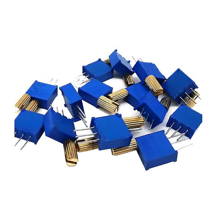
● Trimmer
Preset trimming resistors, commonly referred to as trimming resistors or trimming potentiometers, are miniature variable resistors designed for installation, calibration, and setting on circuit boards without requiring frequent adjustment afterward.
You can think of them as precision adjustment components intended for engineers and equipment manufacturers—not ordinary users—to be "set and forget". They typically require a tool (such as a screwdriver) for adjustment rather than being designed with a knob.
Key Features
Adjustment method: Requires tools (such as flathead or Phillips screwdrivers, or hex wrenches) for adjustment. There are no knobs designed for easy manual turning. This itself is an "anti-misoperation" design.
Compact size: Typically very small in volume, suitable for high-density circuit board mounting.
Mounting methods: Primarily through-hole mounting and surface-mount technology (SMT).
Performance Metrics:
○ High adjustment precision: Especially with multi-turn trimming potentiometers, resistance values can be set with exceptional accuracy.
○ Excellent stability: Once set, its resistance value should remain stable under environmental conditions such as vibration and temperature changes.
○ Mechanical lifespan: Its adjustment cycles (typically 100-200 times) are significantly lower than standard potentiometers (tens of thousands of times), further emphasizing its “set-and-forget” characteristic.
Working Principle and Structural Types
The essence of a trimmer resistor is a three-terminal potentiometer that also operates on the voltage-dividing principle. However, its internal structure and adjustment mechanisms come in various forms:
Top-mounted and side-mounted: Distinguished by the position of the adjustment screw, facilitating use in different PCB layout configurations.
Single-turn and multi-turn:
○ Single-turn trimming potentiometer: Rotating the screw approximately 270-300 degrees adjusts resistance from minimum to maximum. Adjustment is relatively simple and quick, but precision is lower.
○ Multi-turn trimming potentiometers: These require rotating the screw multiple turns (e.g., 10-turns, 15 turns, 25 turns) to adjust the entire resistance range. This provides extremely high resolution and setting precision, making them the preferred choice for precision calibration.
Core Functions and Application Scenarios
The core function of a trimming resistor is to perform “fine-tuning” or “calibration” of a critical electrical parameter during circuit manufacturing, repair, or debugging, optimizing it to its optimal value. Once set, it remains fixed to ensure the long-term stable operation of the equipment.
Its typical applications include:
○ Calibration reference voltage: In power supplies or precision analog circuits, trimming resistors are used to precisely set the reference voltage point of a chip (such as an op-amp, ADC, or voltage regulator).
○ Adjusting sensitivity/gain: Precisely control circuit gain or sensitivity by fine-tuning feedback resistors in sensor interfaces, amplifiers, or filters.
○ Bias Current/Voltage Adjustment: Sets precise static operating points for active components such as transistors and operational amplifiers to optimize linearity and performance.
○ Frequency tuning: In oscillator circuits, it works in conjunction with capacitors to fine-tune the output frequency.
○ Compensation and Matching: Compensate for individual tolerances of other components (such as sensors) or perform impedance matching to maximize signal transmission efficiency.
○ Production Testing and Maintenance: At the end of the production line, workers use trimming resistors to calibrate each product's output parameters (such as voltage, current, and frequency) to standard values. During maintenance, components must also be recalibrated using these resistors after replacement.
Preset trimming resistors are the unsung heroes behind the scenes of electronic devices. Though inconspicuous, they are critical components for achieving product consistency, precision, and reliability. Bridging the gap between fixed resistors (non-adjustable) and panel potentiometers (requiring frequent adjustments), they provide circuit designers with an indispensable tool for fine calibration and compensation. In virtually any application requiring a “one-time precise setting,” you'll find them at work.
● Digital variable resistor
A digital variable resistor, commonly known as a digital potentiometer, is a solid-state semiconductor device that controls its resistance value through digital signals rather than mechanical movement. You can think of it as an “analog” resistor that can be programmed by a microprocessor (such as a microcontroller or CPU).
Its fundamental difference from traditional mechanical potentiometers lies in the absence of movable physical brushes and resistive films. Instead, it emulates their functionality through integrated circuits and electronic switches.
Working Principle and Internal Structure
The core of a digital potentiometer consists of a resistor array and a set of MOSFET analog switches.
Resistor Array: Composed of a series of precision resistors connected in series with identical resistance values, forming a “digital resistor track.” The connection points between these resistors are referred to as taps.
Analog Switch:Each tap is connected to an electronic switch controlled by digital circuitry.
Control Core: A tap position counter that determines which switch to activate based on received digital signals (such as commands from a microcontroller).
Three key terminals (corresponding to traditional potentiometers):
H: Equivalent to the high end of the potentiometer.
L: Equivalent to the low end of the potentiometer.
W: Equivalent to the sliding end of the potentiometer, connected to the currently selected tap.
When the microcontroller sends commands via the communication protocol, the counter inside the digital potentiometer changes its value, thereby closing the current switch and opening a new one. This connects the W terminal to different positions on the resistor array, achieving a change in resistance value.
Core Features and Advantages
Digital potentiometers inherit the two core functions of traditional potentiometers but implement them digitally:
As a programmable resistor: Connect the W terminal to either the H or L terminal to obtain a variable resistor with two terminals. Used for programmable gain amplifiers, frequency tuning of filters, current control, and similar applications.
As a programmable voltage divider: Apply a voltage between H and L to output an adjustable voltage from the W terminal. Used for system calibration, reference voltage setting, power sequencing, etc.
Its significant advantages over mechanical potentiometers include:
○ No mechanical wear, extremely long service life: With no moving parts, it offers exceptional reliability.
○ Compact size, easy to integrate: Typically surface-mount packages, suitable for high-density circuit boards.
○ Remote/automatic control: Adjustable via software commands without manual intervention, facilitating easy integration into automated systems and closed-loop control.
○ High vibration resistance: Unaffected by vibration and impact.
○ No sliding noise: No noise commonly associated with mechanical potentiometers occurs during adjustment.
○ High repeatability: Digital control ensures precise positioning.
Limitations
Digital potentiometers are not perfect and have certain limitations:
Limited resolution: Resistance changes occur in discrete steps, preventing truly continuous, stepless adjustment like that achievable with mechanical potentiometers.
Bandwidth limitations: Internal switches and parasitic capacitance restrict its ability to process high-frequency signals.
Through-hole resistance: Analog switches inherently possess a certain amount of on-resistance, which affects the accuracy of the total resistance value, particularly at low resistance levels.
Current and voltage ratings: The current it can handle and the voltage it can withstand are significantly lower than those of high-power wirewound potentiometers.
Cost: For the simplest applications, it may cost more than a carbon film potentiometer.
● Comparison table: type, symbol, application
| Digital Variable Resistor Comparison Table | |||
| aspect | Type 1: By Interface and Functionality | Type 2: By Memory Characteristics | Type 3: Resistor Array Structure |
| Symbol | Typically, numerical interface identifiers are added to standard resistor symbols: 1. General Symbol: Mark with D or Digi next to the arrow on the sliding end. 2. Detailed symbols: Draw data lines such as I²C or SPI directly. |
Symbols alone typically cannot directly distinguish memory types, but model markings or data sheets will explicitly specify them. | Symbolically indistinguishable, this stems from differences in internal implementation. |
| Type Description | Classified based on digital control interfaces and built-in functions. | Classified based on whether the current resistance setting can be preserved after power loss. | Classified based on the method of generating internal resistance values. |
| Primary Categories | • I²C Interface: Serial clock and serial data two-wire system. • SPI Interface: Chip Select, Clock, Data Input/Output. • Rising/Falling Pulse Interface: Controlled via the UP and DOWN pins. |
• Non-volatility: Built-in EEPROM or similar memory retains settings after power loss. • Volatility: No internal memory; resets to preset value (typically midpoint) upon power loss. |
• Resistor-Switch Network: The most common type, where taps are selected via switches. • Multiplier type: Allows external voltage to exceed its supply voltage, offering greater flexibility. |
| Typical Application Scenarios |
• I²C: Systems requiring connection of multiple devices with limited pin resources (e.g., smartphones, sensor modules). • SPI: Industrial control and communication equipment requiring high speed and strong anti-interference capability. • Up/Down: The simplest control scenario, such as adjusting volume using two buttons. |
• Non-volatility: Devices requiring memory for user settings (such as the final volume of audio equipment), calibration value storage, and systems that do not require repeated initialization. • Volatility: Applications where the microcontroller reconfigures upon each power-up, such as programmable gain amplifiers and dynamically regulated power supplies. |
• Resistor-Switch Network: Suitable for the vast majority of general-purpose applications, such as voltage division, adjustable gain, and tone control. • Multiplier-type: Systems requiring processing of wide-range analog signals, such as audio signal mixing and programmable filters. |
Supplementary Notes and Selection Criteria
Non-standardization of Symbols: The schematic symbol for digital potentiometers has not yet been fully standardized. However, its core consists of a three-terminal potentiometer symbol combined with a digital interface. Understanding this allows recognition of most schematics.
Key Selection Parameters (Beyond the Above Types):
○ Resolution: Number of taps (e.g., 64, 128, 256), which determines the fineness of adjustment.
○ Terminal voltage range: The voltage range that terminals (H, L, W) can withstand determines the maximum signal level they can handle.
○ Resistance tolerance: Accuracy of the nominal resistance value (e.g., ±20%).
○ Temperature coefficient: The degree to which resistance changes with temperature.
Core Advantages: All digital potentiometers share benefits such as zero mechanical wear, remote/automated control capability, high reliability, and compact size, making them ideal for automation and fine-tuning in modern electronic systems.
Using this comparison chart, you can quickly identify the digital variable resistor type best suited for your project based on specific communication method requirements, data retention needs, and signal processing demands.
Symbols for Variable Resistors
The circuit symbols for variable resistors vary depending on their type and function. Correctly identifying the standard symbols for each type of variable resistor is essential for reading and drawing circuit diagrams.
● Standard schematic symbols (IEC / ANSI)
Understanding the circuit diagram symbols for variable resistors under different standards is crucial, as you may encounter them in schematics from various countries or eras. Below are typical symbols based on IEC (International Electrotechnical Commission) and ANSI (American National Standards Institute) standards.
| Typical Circuit Symbol for Variable Resistors (IEC vs. ANSI) | |||
| Type | IEC Standard Symbols (Internationally Recognized) | ANSI Standard Symbols (Commonly Used in the United States) | Note |
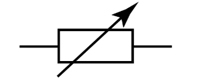
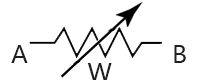
| Universal Potentiometer (Three-Terminal) | 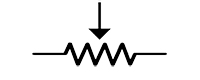 |
 |
Core feature: An adjustable sliding end (arrow). IEC: Use the zigzag resistor symbol. ANSI: Use the rectangular resistor symbol. This is the most basic symbol for a three-terminal device. |
| Used as a rheostat (two-terminal) | 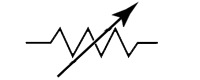 |
 |
Core feature: The sliding end is short-circuited to one fixed end. This clearly indicates that it is connected to the circuit as a two-terminal variable resistor. |
| Pre-set potentiometer (fine adjustment) |  |
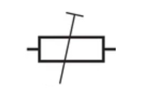 |
Core Feature: Arrows are replaced with “T”-shaped or flat-mouth symbols. This indicates that adjustment using tools such as a screwdriver is required for circuit calibration, not for frequent operation. |
| Digital Potentiometer | 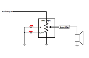 |
Core Feature: The potentiometer symbol is enclosed within the component frame. Control method: Controlled via digital interface pins (e.g., I²C, SPI) outside the enclosure, rather than physical knobs. |
|
Key Differences and Summary of Key Points:
Fundamental Difference: Symbol for Resistance
IEC Standard: Uses a zigzag to represent resistance.
ANSI Standard: Uses a rectangle to represent resistance.
This is the fundamental difference between the two standards for all resistance symbols, not limited to variable resistors.
General Logic: Arrows indicate adjustable
Among all symbols, the arrow is the key indicator of “adjustability.” It points toward the resistor element, representing the concept of a sliding contact.
Unique Identification of Trimming Resistors
Whether in IEC or ANSI standards, trimming resistors are uniquely identified by changing the arrow to a “T” shape, making them immediately recognizable in circuit diagrams.
Compound Symbol for Digital Potentiometer
The symbol for a digital potentiometer is a “composite” symbol. It incorporates the standard potentiometer symbol (which may be IEC or ANSI style) within a component frame, with additional numbered pins added to indicate its integrated circuit nature.
Recommendation: In modern engineering practice, IEC standards are becoming increasingly prevalent. However, the most reliable approach is to be able to distinguish between these two symbol systems. When reading circuit diagrams, a rectangular resistor symbol likely follows the ANSI standard, while a sawtooth symbol typically represents the IEC standard.
● How to interpret the arrow and contacts in the symbol
In the symbol for a variable resistor, the arrow and connection points directly determine its function and how it connects in a circuit. Generally, the arrow indicates adjustability, while the connection points represent its functionality. Below, we'll understand their meaning through a systematic breakdown.
Arrow: Represents the "sliding end" or "brush"
The arrow is the soul of the variable resistor symbol; it always points toward or connects to the sliding terminal.
Physical Meaning: This arrow represents the metal brush that slides along the resistive element within the physical device. When you turn the potentiometer's knob, you are moving the part represented by this arrow.
Electrical Meaning: The terminal indicated by this arrow is the circuit's output terminal or signal extraction point.
In a voltage divider circuit, it serves as the output voltage terminal.
In rheostat mode, it functions as one connection point of the variable resistor.
The shape of the arrow indicates the adjustment method:
Hollow or solid arrow: Typically indicates a standard manual-adjustment potentiometer (with a knob).
"T"-shaped or flat-tip arrow: Indicates a trimmer potentiometer, which requires adjustment with a screwdriver.
Contact: Determines the functional mode
The number and configuration of the contacts determine whether this variable resistor functions as a “potentiometer” or a "variable resistor."
Mode 1: Three-Terminal Connection (Potentiometer Mode - Used as a Voltage Divider)
This is the most complete connection method, utilizing all three contact points.
Symbol characteristics: The arrow independently leads to a terminal without shorting to any fixed terminal.
Contact Point Identification:
Two outer terminals: Connected to both ends of the resistive element. The resistance value between them is fixed and represents the component's nominal resistance value.
Center terminal (arrow): Sliding contact, outputs an adjustable voltage.
Circuit Function: Apply a voltage across two fixed terminals to obtain a variable, voltage-divided output between the sliding terminal and either fixed terminal.
Typical applications: Volume control, reference voltage setting.
 |
* A-B: Total resistance (fixed) * A-W: Partial resistance (variable) * W-B: Partial resistance (variable) * W is the output terminal |
Mode 2: Two-Terminal Connection (Rheostat Mode - Used as a Variable Resistor)
This connection method uses only two terminals, treating the potentiometer as a pure variable resistor.
Symbol characteristics: The arrow is connected to one of its fixed ends.
Contact Point Identification:
Two contacts in use: one is the sliding contact (indicated by the arrow), and the other is the fixed contact shorted to it.
Unused contact: The third contact is left floating or disconnected.
Circuit Function: The resistance value between these two terminals can be adjusted. By moving the sliding contact, the resistance value in the circuit can be altered to control the current flow.
Typical Applications: Current limiting, dimming, motor speed control (in simple circuits).
 |
* We only use terminals A and W. * The resistance between A and W is variable. * Terminal B is left floating or unused. |
Comprehensive Identification Steps and Examples
When you see a variable resistor symbol in a circuit diagram, follow these steps:
Locate the arrow: First, identify the arrow—this is the sliding end.
Analyze connections: Check whether the arrow has a direct connection to a fixed terminal.
If the arrow is isolated -> It is a three-terminal potentiometer used for voltage division.
If the arrow is shorted to the fixed terminal -> It is a two-terminal rheostat used for variable resistance.
Terminal identification:
For the three-terminal mode, confirm which two terminals the input voltage is applied to (typically the two fixed terminals) and from which terminal the output voltage is taken (the sliding terminal and ground).
For the two-terminal mode, confirm where it is connected in series within the circuit to control the current.
Summary: Remember this core principle—In many circuit diagrams, a single arrow is used to indicate an adjustable resistor(often configured as a voltage divider), while variants of the symbol are used to show different connection modes. Once you grasp this, you'll easily decipher the intent of most variable resistors in circuit diagrams.
● Symbol for each type (potentiometer, rheostat, trimmer)
In electronic circuit diagrams, different types of variable resistors are represented by specific graphical symbols that characterize their physical properties and functions. These symbols directly relate to their typical applications within circuits.
Three-terminal potentiometer
The potentiometer symbol depicts a resistor shape with an arrow touching it, extending three terminals. This three-terminal structure is its core feature. It visually represents the physical process where a sliding contact moves along the resistive element, continuously dividing the voltage between two terminals. This is precisely its typical application as a voltage divider, such as in audio equipment for volume control. Audio signals are input to the two fixed terminals of the symbol, while the signal is output from the sliding terminal represented by the arrow. Rotating the knob changes the position of the sliding terminal, smoothly altering the amplitude of the output signal to achieve volume adjustment.
Two-terminal resistor
The symbol for a rheostat depicts a resistor with its arrow terminals directly connected to one fixed terminal by a short line, forming two effective access points. This configuration explicitly indicates its use as a two-terminal variable resistor. Its function is to directly limit circuit current by altering its own resistance value. A classic application is in dimming circuits for old-style incandescent bulbs, where the component represented by this symbol is connected in series with the bulb. Moving the sliding terminal alters the series resistance value, thereby controlling the current flowing through the filament to achieve brightness adjustment.
Preset resistor
The symbol for a preset trimmer resistor resembles that of a potentiometer, but the key difference lies in its sliding terminal being replaced by a “T” shape. This “T” shape symbolizes the tool interface requiring adjustment with a screwdriver. In a circuit, it does not represent a function requiring frequent user operation but rather serves as a calibration point. For example, in a sensor signal conditioning circuit, it is used to precisely set the amplifier's reference voltage or gain. Engineers use tools to fine-tune its position during product calibration. Once set, it remains fixed to ensure the circuit operates at its optimal state.
Therefore, by identifying whether the arrow is independent, shorted, or replaced by a “T” symbol, engineers can quickly determine on the schematic whether the component's role is for signal voltage division, current limiting, or parameter calibration.
| Type | Terminals | Typical Symbol | Main Function |
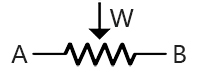
| Potentiometer | 3 |  |
Voltage divider |
| Rheostat | 2 | 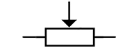 |
Current control |
| Trimmer potentiometer | 3 |  |
Precision calibration |
● How to identify in circuit diagrams for GCSE
In GCSE Physics or Design Technology, identifying circuit diagram symbols is a core skill. The symbols used in examinations typically follow a standardized simplified notation system. GCSE exam boards (such as AQA, Edexcel, OCR) generally employ a set of symbols closely aligned with British Standard BS 3939. These symbols are characterized by their simplicity and intuitive nature.
| Component Name | Key Identification Features |
| Fixed resistor | A simple rectangular box. Indicates that the resistance value cannot be altered. |
| Variable resistor | A diagonal arrow pierces through the rectangular frame. This arrow symbolizes the sliding end and adjustability. |
| Potentiometer (three-terminal) | The symbol is identical to that of a variable resistor. At GCSE level, the distinction between the two is not typically made rigorously. The determination is based on the circuit connection method: if all three terminals are used, it is a potentiometer; if only two are used, it is a variable resistor. |
GCSE Circuit Diagram Symbol Recognition Techniques
Find the arrow: The arrow almost always indicates “adjustable” or “variable.” In a variable resistor, it represents the sliding contact.
Remember the shape:
Rectangle = Resistor
Parallel lines = Battery or capacitor
Triangle + line = Diode
Circle + letter = Measuring instrument
Is the component connected in series on a single line, or in parallel between two lines? This determines whether it functions like an ammeter (series) or a voltmeter (parallel).
● Practical hanging-off: brand packaging to symbol matching
In engineering practice, circuit diagram symbols represent only an idealized model. Selecting the appropriate physical components—involving brand, package, and parameters—is crucial for achieving the design's intended functionality.
Correspondence Between Symbols and Encapsulation
Circuit symbols define the electrical function of a component, while the package defines its physical form and mounting method.
Universal three-terminal potentiometer symbol:
Corresponding Package: This typically represents a panel-mounted device featuring a knob or toggle switch. Examples include rotary potentiometers for volume control or slide potentiometers on dimmable desk lamps. The three terminals on the symbol correspond to the three pins on the physical component.
Symbol for trimming resistor:
Corresponding Package: This specifically refers to small components mounted directly on the board that require adjustment with a screwdriver. These come in various package types, such as the common top-adjustable or side-adjustable styles. Their compact size is accurately indicated by the “T” shape in their symbols, which signifies their adjustment method.
Digital potentiometer symbol:
Corresponding Package: This represents an integrated circuit. Its package is typically surface-mount type, such as SOP, SSOP, or QFN. The numbered interface pins in the symbol (e.g., SCL, SDA) correspond one-to-one with the actual pins on the chip.
Implied Association Between Brand and Packaging
Brands often represent quality, reliability, and specific product lines. Some top international brands offer products spanning a wide range, from consumer-grade to automotive-grade. When faced with high-specification design requirements, engineers prioritize these brands. They provide an exceptionally diverse array of packaging options.
Some brands are highly regarded worldwide, particularly in the fields of trimming potentiometers and precision potentiometers. When the trimming resistor symbol appears in a circuit diagram, Bourns' Trimpot® series is often one of the preferred physical references.
Some brands, as major suppliers of generic components, offer products with high cost-performance ratios and are frequently used in consumer electronics. In cost-sensitive designs, the physical components corresponding to the symbols are likely sourced from such brands.
Core Elements of Practical Alignment
From Symbols to Component Selection: When reading circuit diagrams, one must not rely solely on symbols but must consult the adjacent component annotations. For example, a trimmer resistor symbol might be labeled “Bourns 3296W 10 kΩ,” which directly specifies the brand, series, resistance value, and package size.
The Decisive Role of Packaging: Packaging directly impacts PCB layout design. An SMD digital potentiometer for signal fine-tuning and a high-power wirewound potentiometer for power regulation may share similar symbols, yet their physical dimensions and thermal management requirements are fundamentally different.
Interface Compatibility: For digital potentiometers, the digital interface type specified in the symbol (e.g., I²C or SPI) must match the host microprocessor's interface; otherwise, communication will fail.
In practice, symbols serve as the starting point for design. Engineers must select a real component from a specific brand's product library that features a suitable physical package, matching parameters, and controllable cost. This selection must be based on the symbol's defined functionality and aligned with the circuit's voltage, current, precision, and environmental requirements. Only then can the symbol on the schematic be transformed into a functional circuit.
Construction, Operation & Applications
● How a variable resistor works
The core principle of variable resistor operation lies in mechanically altering the effective length of the resistive element within the circuit.
Its internal structure consists of a fixed-length resistive element connected at both ends to two fixed terminals. A movable sliding contact (slider) is pressed against the resistive body. When used as a rheostat, only the sliding terminal and one fixed terminal are connected to the circuit. At this point, the current path flows into the fixed terminal, traverses part of the resistive element, and exits through the sliding terminal. Turning the adjustment knob physically moves the sliding contact, directly altering the length of resistive material through which current flows. Increasing the length raises resistance, reducing circuit current; decreasing the length lowers resistance, increasing current. This is precisely how old-fashioned dimmer lamps operate.
When used as a potentiometer, all three terminals are utilized. A voltage is applied between the two fixed terminals, creating a voltage gradient across the entire resistive element. At this point, the sliding contact functions as a voltage probe. Its position determines the voltage value it “taps” from the resistive element. Turning the knob continuously changes the output voltage division ratio, enabling precise control over signal levels—such as adjusting the volume on audio equipment.
In short, whether altering resistance or voltage division, the fundamental principle involves dynamically and continuously modifying the circuit's topology through the physical displacement of sliding contacts.
● Typical internal construction & backing materials
The internal structure of a variable resistor is built around a core principle: altering the effective resistance length through mechanical sliding.
A typical structure comprises three key components:
Resistor element
This is the fundamental material for achieving resistive functionality, with common types including:
Carbon Film: Deposits a carbon-based film onto insulating porcelain rods, adjusting resistance through helical grooves. This is the most economical solution, widely used in standard potentiometers, but offers average wear resistance and noise performance.
Metal Film: Utilizes metal or metal oxide films, outperforming carbon film with lower temperature coefficients and noise levels. Commonly employed in demanding applications such as instrumentation and metering equipment.
Wire-wound: Specially formulated resistance wire is wound around an insulated core. This structure can withstand high power and offers high precision, but exhibits poor high-frequency characteristics and step-like resistance changes during sliding.
Conductive plastic: Utilizing a specialized plastic formulation as the resistive material, this design achieves near-infinite resolution and exceptionally long mechanical life, commonly employed in high-precision servo systems.
Sliding contact
Typically, it consists of a flexible metal strip (contact brush) that maintains reliable contact with the resistive element under pressure. When the knob or slider is moved, it slides along the surface of the resistive element, altering the position of the electrical connection point. The material and shape of the contact directly influence the stability of contact resistance and the tactile feedback during operation.
Collector and terminal
Two fixed terminals are connected to opposite ends of the resistive element. The sliding contact connects to a third terminal (sliding terminal) via a current collector (such as a metal slip ring), ensuring a continuous electrical connection throughout the sliding motion.
Among these materials, carbon film and synthetic film potentiometers offer the lowest cost, while wire-wound structures provide the highest power handling capability. Conductive plastic and metal-ceramic variants excel in longevity and stability.
● Real-world applications in electronics procurement
In the procurement of electronic components, the selection and application of variable resistors is a task that requires comprehensive consideration of both technical parameters and supply chain realities.
Parameter trade-offs during the selection phase
The procurement process begins with the engineer's bill of materials. For potentiometers, nominal resistance and power rating are fundamental, but the actual selection process involves far more than that.
Signal conditioning circuits prioritize resistance variation patterns and sliding noise, typically selecting carbon film or conductive plastic potentiometers.
Power adjustment circuits place greater emphasis on rated power and temperature stability, making wirewound or metal-ceramic potentiometers the preferred choice.
Space-constrained designs will directly specify surface-mount packaging, while panel circuits requiring frequent adjustments must be paired with corresponding knob accessories.
Strategic Choices for Brands and Channels
The purchasing party needs to develop strategies based on product positioning and reliability requirements
Automotive electronics or high-end industrial equipment typically specify brands such as Alpine or Burr & Stone to ensure long-term stability.
Under cost pressures, consumer electronics may opt for generic series from certain brands or accept alternative models, but rigorous compatibility verification must be conducted.
For digital potentiometers, procurement must also verify whether the interface protocol matches that of the main control MCU.
Practical Considerations for Production and Material Preparation
If trimming resistors are used for calibration, the versatility of their adjustment tools must be tested on the production line; otherwise, it will severely impact production efficiency.
For products with a long expected lifecycle, procurement will assess whether components are subject to imminent discontinuation and proactively plan for alternatives or execute final bulk purchases.
Delivery time is a critical variable. Imported potentiators often have lead times exceeding 12 weeks, frequently forcing procurement personnel to seek spot market channels or initiate substitution processes. This requires close coordination between technical and commercial departments.
In practice, procurement personnel must translate abstract circuit symbols into specific material codes, striking a balance between technical requirements and commercial realities. A successful procurement case means the right components arrive at the production line at the right time and at a reasonable cost, ensuring stable operation throughout the product's entire lifecycle.
● Circuit case study: adjusting volume, dimming, sensor feedback
Below, we will demonstrate how variable resistors function in practice through three specific circuit examples. These cases highlight their distinct core functions.
Case 1: Volume Adjustment (Voltage Divider Function)
This is the most classic application, utilizing the voltage divider principle of a potentiometer.
Circuit Connection:
The audio signal source (such as a mobile phone's audio output) connects to the fixed terminals at both ends of the potentiometer.
The amplifier input connects to the slider terminal of the potentiometer and ground (typically the signal source ground).
Work Process:
When you turn the knob, the sliding contact moves along the resistive element.
This sliding contact divides the entire resistor into two sections, “drawing” a portion of the voltage from between them to feed the amplifier.
When the knob is moved to the upper position, the amplifier receives nearly the full input signal, resulting in maximum volume.
When the knob is moved to the lower position, the amplifier receives almost no signal, resulting in minimum volume.
Practical Considerations: Logarithmic potentiometers are typically used in this circuit because human ears perceive volume on a logarithmic scale. This ensures that the perceived increase in volume is linear with the rotation angle of the knob.
Case 2: Dimming (Variable Resistance Function)
In traditional incandescent lamp dimming circuits, variable resistors are used as variable resistors.
Circuit Connection:
Connect the potentiometer to the circuit in resistor mode: short its sliding terminal to one of its fixed terminals.
Connect this “two-terminal device” in series with an incandescent lamp before connecting it to the power source.
Work Process:
When the knob is turned to the position of minimum resistance, the resistance it introduces into the circuit is very low, causing little obstruction to the current flow, and the light bulb shines brightest.
When the knob is turned to the position of maximum resistance, the resistance it introduces into the circuit increases, limiting the circuit current, and the light bulb dims.
Practical Considerations: This is an inefficient dimming method because electrical energy consumed by the potentiometer is converted into heat. Consequently, in high-power applications, it has been replaced by electronic dimmers based on semiconductors (such as triacs). This circuit must use a power-rated potentiometer (such as a wire-wound potentiometer), otherwise it will burn out due to overheating.
Case 3: Sensor Feedback (Position Sensing)
Here, the potentiometer itself functions as a sensor, converting physical position into an electrical signal.
Circuit Connection:
Apply a stable reference voltage to the two fixed terminals of the potentiometer.
Mechanically connect the sliding terminal to the object requiring detection (e.g., accelerator pedal, robotic joint).
Feed the output signal from the sliding terminal into the analog input pin of the microcontroller.
Work Process:
When the measured object moves, it drives the sliding end to move.
The voltage output from the sliding end is precisely proportional to its physical position.
By reading this changing voltage, the microcontroller can accurately calculate the object's current position or angle.
Practical Considerations: This application is highly dependent on the potentiometer's linearity and mechanical lifespan. High-precision equipment utilizes conductive plastic or precision wire-wound potentiometers to ensure accurate and enduring reliability of position signals.
Specifications & Purchasing Tips for Engineers & Buyers
● From symbol to specification: power rating, resistance range, tolerance
This is a very practical issue concerning engineering and procurement coordination. From a symbol on a circuit diagram to a specific part number on a purchase order, engineers and procurement personnel must reach consensus on the following core specifications.
From Symbols to Specifications: Key Selection Considerations for Engineers and Purchasing
Circuit symbols define the function of components, but precise specifications must be assigned to them to ensure reliable circuit operation.
Power Rating
This is the primary parameter concerning circuit reliability and safety.
Engineer's Considerations:
The maximum power a component may withstand in a circuit must be calculated using Ohm's Law: P = I²R or P = V²/R.
Critical Action: The rated power of the selected potentiometer must be at least 1.5 to 2 times the calculated value, providing sufficient safety margin to prevent overheating damage.
Variable resistor symbol: In power tuning or power adjustment circuits, the variable resistor symbol must correspond to physical components such as high-power wirewound types.
Focus of Procurement Personnel:
Power ratings directly correlate with cost, size, and brand selection. A 2W wirewound potentiometer costs significantly more and is substantially larger than a 0.25 W carbon film potentiometer.
High-power components may need to be sourced from specific brands, as generic brands may not offer them.
Resistance range
This determines the circuit's adjustment range and precision.
Engineer's Considerations:
Voltage In many low-noise analog designs, voltage adjustment often uses resistors below about 10 kΩ to help keep thermal noise and interference under control.
Signal conditioning/high-impedance circuits: Resistance values of 100 kΩ or even 1MΩ may be selected.
Key Action: Determine a nominal resistance value that satisfies the adjustment range without adversely affecting other parts of the circuit (such as load effects).
Key Considerations for Procurement Personnel:
Resistance values are fundamental parameters, and inventory is typically sufficient. However, be wary of non-standard resistance values, as they may involve long lead times and higher costs.
Tolerances must be confirmed with the engineer. The cost of 1% precision is significantly higher than that of 20% precision.
tolerance
This reflects the initial precision of the resistance value, directly impacting the consistency of circuit performance
Engineer's Considerations:
Voltage Divider/Reference Voltage Applications: Requires tighter tolerances, such as ±5% or ±1%, to ensure output voltage accuracy.
Rough adjustment/current limiting applications: A ±20% general tolerance is typically acceptable.
Key Action: Distinguish between tolerance-sensitive and non-tolerance-sensitive sections in the circuit to avoid unnecessary cost overruns from using high-precision components for all positions.
Key Considerations for Procurement Personnel:
Tolerance is one of the primary price drivers. Each increase in precision grade can lead to a significant rise in cost.
When procuring components, it is essential to clarify whether high-tolerance parts are truly necessary. In most applications, such as volume controls, a tolerance of ±20% is entirely sufficient, as end users can manually adjust the control to the desired position.
Collaborative Selection Recommendations
Engineers should not merely list “10 kΩ variable resistor” on the BOM (Bill of Materials), but must provide complete specifications that include at least the resistance value, tolerance, rated power, and package type.
Purchasing personnel must consult engineers to confirm electrical specifications and package compatibility when receiving requests for alternative models. Price comparisons alone are strictly prohibited.
Both parties shall jointly establish and maintain a preferred device library, prioritizing models that meet performance requirements, ensure a stable supply, and offer reasonable costs, thereby achieving an optimal balance between design efficiency and supply chain security.
● Brands & typical part-number cross-references
This is a cross-reference based on common brands and typical part numbers encountered in engineering practice. These models are highly recognizable within the industry and often serve as benchmarks for design selection and finding alternatives. This table aims to provide engineers and procurement personnel with a quick physical reference for matching abstract symbols to specific materials.
| This table is designed to provide engineers and procurement personnel with a quick physical reference for matching abstract symbols to specific materials. | |||
| Device Type | Typical Brands | Example of a typical part number | Specification Highlights and Notes |
| Universal Knob Potentiometer | Alps Alpine | RKO9K Series (e.g., RKO9K1130AJ5) | Single-gang, switchable/non-switchable options. Offers excellent tactile feedback and is a common choice for audio equipment. |
| Nidec Copal | RV24YN Series | Industrial-grade reference materials, featuring robust construction and extended service life, are widely used in instrumentation and metrology. | |
| Trimmer potentiometer | Bourns | 3296W Series(e.g., 3296W-1-103LF) | Top-tier tuning, multi-turn (~25 turns), high precision. Industry de facto standard, virtually synonymous with trimming resistors. |
| Bourns | 3386 Series(e.g., 3386P-1-103LF) | Single-coil, side-wound, priced below 3296, suitable for applications where extreme performance isn't required. | |
| Vishay | T93YA Series | Sealed type, high reliability, suitable for harsh environments. | |
| Wire-wound power potentiometer | Vishay | PRV Series (e.g., PRV6SAABABX25103KA) | Ceramic tubular, high power (5W and above), used for power regulation and high-current control. |
| Digital Potentiometer | Analog Devices | AD52xx Series (e.g., AD5241BRZ10M) | High performance, high precision, offering multiple interfaces and non-volatile storage options. |
| Microchip | MCP41xxx/42xxx Series (e.g., MCP41010-I/P) | SPI interface, offering high cost-effectiveness, is a common choice for microcontroller systems. | |
| Renesas | ISL Series (e.g., ISL95311) | Often integrated into complex power management ICs for dynamic voltage regulation. | |
| Conductive Plastic Potentiometer | Vishay | SPW Series | Nearly infinite resolution, extremely long lifespan (>50 million cycles), for servo systems and precision instruments. |
Practical Considerations for Using Reference Tables
Part Number Decoding: Taking Bourns 3296W-1-103LF as an example:
3296W:Serial number, representing the packaging and mechanical structure.
1:Resistance characteristic code (e.g., 1 represents linear).
103: Resistance value, 10 x 10³ Ω = 10 kΩ.
LF: Pin/Package Options.
Understanding this coding rule is essential for reading data manuals and placing accurate orders.
The Value of Cross-Reference: When the specified model in the design (e.g., Alps RK09K) cannot be used due to delivery lead time or cost issues, procurement may suggest functionally equivalent alternative models to the engineer (e.g., Yageo potentiometers with identical specifications).
When creating a BOM (Bill of Materials), engineers may annotate key parameters with "or equivalent specifications" to provide flexibility for procurement, but core brands and models must be locked as preferred choices.
Brand Positioning:
Alps, Bourns, Vishay: Representing high performance and high reliability, they are used in applications with stringent requirements for performance and service life.
Yageo, KOA: Offering a wide range of cost-effective general-purpose components, they are the preferred choice for cost-sensitive consumer electronics.
ADI, Microchip: In the field of digital potentiometers, it sets the benchmark for performance and mainstream applications.
The core function of this cross-reference table is to establish a common language from design to procurement, ensuring that symbols on drawings can be efficiently and accurately materialized into physical components that meet requirements.
● Common pitfalls: symbol mismatches, wrong taper type, wrong mounting
In practical applications, issues such as symbol mismatches, incorrect taper type, and improper installation methods are real challenges frequently encountered by engineers and procurement personnel during the transition from blueprints to finished products. These problems are unlikely to appear in textbooks, yet they are sufficient to bring project progress to a standstill.
Symbolic Discrepancy: The Gap Between Ideal and Reality
Circuit diagram symbols represent a highly simplified model, while the actual physical components are far more complex.
Common Issue: A generic three-terminal potentiometer symbol was drawn on the schematic, leading procurement to purchase the cheapest carbon-film potentiometer available. However, in the actual circuit, it was used as a voltage divider to provide a reference voltage for a high-precision ADC. The poor temperature coefficient and stability of the carbon-film potentiometer resulted in the entire system failing to meet accuracy requirements.
Root Cause: Symbols define only electrical connections without specifying technical implementations. Behind each symbol lies a physical component made from different materials and processes—carbon film, metal film, wire-wound, conductive plastic—whose performance, lifespan, and cost vary dramatically.
Workaround: Engineers must explicitly specify the type in the bill of materials or schematic annotations, such as “metal film potentiometer” or “multi-turn precision trimmer resistor,” rather than relying solely on symbols.
Incorrect “taper type”: Incorrect application of resistance variation patterns
The “taper type” here actually refers to the resistance variation characteristics, specifically the relationship between resistance and the angle of rotation.
Common Issues:
In the volume control circuit, a linear potentiometer was mistakenly used: this causes the volume to increase sharply with just a slight turn of the knob, while the latter half of the adjustment range shows almost no change, resulting in an extremely poor user experience.
The misuse of a logarithmic potentiometer in the voltage divider position sensor caused the microcontroller to read positions that were not proportional to the physical position, resulting in nonlinear errors in the control system.
Root Cause: Failure to understand the appropriate applications for linear and logarithmic resistance variation patterns. Linear potentiometers are suitable for voltage division and position detection; Logarithmic (audio) potentiometers are primarily used for volume control and other applications that follow human hearing perception.
Workaround: Clearly specify the type code during selection, such as Type B (linear) or Type A (logarithmic), and carefully verify the curves in the data sheet.
Incorrect Installation Method: Disconnect Between Mechanical and Electrical Design
This is a common cause of production delays and additional costs.
Common Issues:
PCB packaging error: The schematic symbol is correct, but the PCB pad dimensions and spacing designed for it do not match the actual pin packaging, resulting in soldering failure.
Improper placement of trimming resistors: Positioning trimming resistors requiring tool adjustment in the center of densely populated circuit boards, surrounded by large components, renders them inaccessible during production calibration or maintenance.
Panel cutout mismatch: The shaft size specified for the knob potentiometer (e.g., 6mm smooth shaft) does not match the panel cutout (e.g., 6.2mm) or the knob's mounting hole.
Root cause: Disconnect in the design process. Electrical engineers focused solely on circuit connections, while structural engineers concentrated exclusively on aesthetics. Neither party cross-checked the physical dimensions of components or installation interfaces.
Workaround: Establish a unified component library where schematic symbols, PCB packages, and 3D models for each component are correctly associated. Conduct comprehensive mechanical interference checks before releasing production files.
In short, the key to avoiding these pitfalls lies in collaborative design. Engineers must look beyond symbols when selecting components and consider their actual physical implementation; procurement personnel cannot focus solely on model numbers but must understand the significance of critical parameters; and all design decisions must be validated under real mechanical constraints.
● Replacement and compatibility suggestions for procurement
From a distributor's perspective, substitution and compatibility form the core of daily operations. This is not merely a technical issue but a strategic element concerning customer trust and supply chain resilience. When clients (typically procurement officers or engineers) inquire, “Is there an alternative for this component?” our internal evaluation process immediately kicks into gear—a task far more complex than simply comparing specification sheets.
Three Scenarios for Triggering Substitution
Delivery Killer: Original manufacturer's lead time skyrocketed from 8 weeks to 52 weeks, leaving the customer's production line unable to wait.
Price Pressure: The customer's project entered mass production phase, facing intense cost-cutting competition.
Discontinuation Notice: Received EOL or NRND notifications from the original manufacturer, necessitating the search for next-generation solutions.
Four Levels of Substitute Evaluation
Internally, we categorize alternative solutions into several tiers and clearly explain the associated risks to our clients:
Tier 1: Plug-and-play compatible replacement
Description: Different brands, but with identical packaging, pinouts, and key parameters. For example, if a customer uses Bourns 3296W-1-103LF, we recommend Unikeyic Electronics' equivalent model.
Risk: Minimal. However, customers should still be advised to conduct small-batch board testing to verify soldering yield and basic functionality.
Tier 2: Parameter Downgrade/Upgrade Substitution
Description: Compatible with the original package and basic functionality, but certain parameters differ. For example, ±20% tolerance replaces ±10% tolerance, or models with higher rated power replace the original models.
Risk: Medium-low. Confirm with the customer whether parameter differences affect their product performance. Downgraded alternatives must receive explicit approval from the customer's design team.
Tier 3: Functional Substitution (Solution Level)
Description: When no direct replacement is available, provide alternative solutions with equivalent functionality. The most typical example is recommending that customers replace a mechanical potentiometer + MCU ADC sampling solution with a digital potentiometer.
Risk: High. Involves circuit and software modifications, suitable only for customers with R&D capabilities who are willing to alter the design.
Tier 4: Non-Recommended Alternatives
Description: Certain components sourced from non-reputable channels may appear to meet specifications but lack long-term reliability verification.
Internal Policy: We do not proactively recommend such products unless explicitly requested by the client and accompanied by a signed risk assumption agreement. Sacrificing long-term client trust for short-term gains is not worth the cost.
Key Actions for Building Trust
Provide data, not guesswork: We will provide both OEM and alternative model data sheets simultaneously, highlighting key differences to empower our customers' engineers to make informed decisions.
Share market intelligence: Proactively inform customers about the root causes of stockouts or price hikes—whether they stem from wafer production capacity issues at a specific original manufacturer or geopolitical factors—to help them anticipate risks.
Preparing “Sample Kits”: For common alternative combinations, we prepare small-batch sample kits for urgent client testing—a more compelling approach than empty promises.
For distributors, the ability to provide excellent alternative recommendations is a core value. It requires us to be more than just a warehouse—we must serve as a technical intelligence hub and supply chain consultant. A successful alternative solution makes customers feel we've helped them solve a problem, rather than simply selling them a different part.
Why Unikeyic Electronics?
● Our expertise in electronic components distribution
From an industry insider's perspective, Electronics, as an active independent distributor of electronic components, demonstrates its professional capabilities primarily through the following practical dimensions:
Unikeyic Electronics' core value lies in resolving supply chain uncertainties for electronics manufacturers, with its capability development closely aligned with market demands
1. Core Value: Sourcing and Supply Assurance for Scarce Materials
This is the foundation of their business. When clients face production stoppage risks due to extended OEM lead times, discontinued components, or sudden shortages, Electronics leverages its established global procurement network to swiftly locate available inventory. They excel at handling “unplanned” procurement needs, providing clients with a lifeline for production.
2. Key Skills: Professional Component Identification and Supply Chain Management
In the realm of independent distribution, quality is the lifeline. One of Electronics' core competencies lies in:
Supply Chain Traceability: We maintain a rigorous verification process for component sourcing channels, prioritizing procurement from authorized distributors or reliable factory channels to mitigate risks.
Quality Control: Possess or collaborate to establish third-party testing laboratories to conduct component unboxing inspections, electrical performance testing, X-ray analysis, decoding tests, and other procedures to effectively identify refurbished, counterfeit, or domestically produced imitation products.
3. Technical Services: Recommendations for alternative solutions to a certain extent
Facing long-term component discontinuities or shortages, they not only offer immediate availability but also leverage their experienced sales and application engineering teams to provide proven alternatives tailored to customers' specific applications. For instance, they recommended replacing discontinued mechanical potentiometers with Microchip's digital potentiometers and outlined key software modification points. This elevates their role from mere “product sellers” to comprehensive solution providers.
4. Flexible Inventory and Financial Strategies
Unlike traditional authorized distributors, Electronics typically maintains strategic inventory for common part numbers that may face shortages based on market forecasts. This “reservoir” model enables them to provide relatively stable supply to customers during market price increases, though prices are generally higher than the standard levels in authorized channels. This fundamentally represents a risk management capability grounded in market insight.
In summary, the expertise of Unikeyic electronics independent distributors can be encapsulated as “delivering certainty to customers within non-ideal supply chain environments.” They fill gaps beyond the standard service offerings of authorized distributors, serving as a vital buffer for manufacturers navigating supply chain volatility. The depth of their specialization is directly reflected in the reliability of their sourcing, the rigor of their quality control, and the practicality of their technical advice.
● How we support engineers with symbols, datasheets and selection
From an engineer's perspective, a top-tier electronic component distributor delivers far more than just “selling products.” Electronics provides genuinely valuable support, with services seamlessly integrated into engineers' design workflows. Electronics' core strength lies in transforming fragmented information into efficient design tools, specifically manifested in:
Symbol and Model Support: Accelerate Design Import
For engineers, manually drawing schematic symbols and PCB packages is a highly repetitive and error-prone task. Electronics offers the following services:
Mainstream EDA library files: On its official website or customer portal, it provides component libraries compatible with mainstream design software such as Altium Designer, KiCad, and OrCAD. After searching for a part number (e.g., Bourns 3296W), engineers can directly download complete library files containing schematic symbols, PCB packages, and 3D models.
Model Quality: These library files are not automatically generated but manually verified to ensure pin definitions and pad dimensions precisely match physical components, preventing board rework due to packaging errors.
Data Integration and Analysis: Lowering the Barriers to Information Access
Data sheets serve as the “instruction manual” for components, but original manufacturer manuals are often lengthy. What Electronics can do is:
Key Parameter Extraction: On the component page, clearly list core parameters such as resistance range, tolerance, power rating, temperature coefficient, and package dimensions in a tabular format, enabling engineers to quickly determine suitability.
Cross-reference for alternative models: This is its core value. The page clearly states “Direct replacement for XXX” or “Functionally compatible with XXX but with different pinouts,” providing engineers with viable alternatives—especially when primary models are out of stock or prohibitively expensive.
Discontinuation and Risk Alerts: Promptly label components on their product pages with “Not recommended for new designs” or “Discontinued,” and proactively recommend alternatives to help engineers avoid selecting components slated for phase-out.
Contextual Selection Support: From "Functional" to "User-Friendly"
Engineers don't need product catalogs—they need solutions. That's where Unikeyic Electronics' technical support team comes in:
Application-Oriented Filtering: In addition to electrical parameters, the website filter should include “Recommended Applications” options such as “Audio Volume Control,” “Precision Fine-Tuning,” and “Motor Speed Control.” Upon selection, the system will automatically recommend the most suitable type (e.g., logarithmic potentiometers, multi-turn Trimmer potentiometer, power wirewound potentiometers).
Technical Consultation: When engineers hesitate over questions like “How to set the I²C address for a digital potentiometer” or “What are the specific differences in lifespan between conductive plastic and carbon film,” a technical sales team capable of providing swift, accurate answers is crucial.
Sample Service: We provide a convenient sample request process, enabling engineers to receive physical samples for verification and testing before finalizing designs. This is crucial for confirming tactile feel, dimensions, or software compatibility.
In short, Electronics' professional capability lies in its ability to function as an efficient “design information hub.” By providing precise, readily available design resources, it frees engineers from tedious data searches and basic modeling tasks. Simultaneously, leveraging its market insights and technical expertise, it helps customers mitigate supply chain and technical risks during the initial component selection phase.
Conclusion
● Core Definition and Functionality
A variable resistor is an electronic component whose resistance value can be manually or automatically adjusted. Its core function is to dynamically control voltage (as a voltage divider) and current (as a rheostat) within a circuit. It serves as the foundation for circuit parameter adjustment, user interaction, and signal control.
● Types, Symbols, and Internal Structure
Main Types
Mechanical: Adjusted via physical contacts, including universal potentiometers, rheostats, and trimmer resistors.
Digital: An integrated circuit that controls resistance values through digital signals.
Sensitive type: Resistance automatically changes with environmental factors such as temperature and light exposure, e.g., thermistors.
Circuit Symbols: Symbols are the visual language of functionality
Carbon film: Low cost, versatile.
Metal film/metal ceramic: More stable, used in instruments.
Wirewound: High power rating, high precision.
Conductive plastic: High resolution, ultra-long lifespan.
● Practical Application and Selection Considerations
Typical Application Circuit
Volume Control: Utilizes its voltage-dividing function.
Dimming (Old-Style): Utilizes its variable resistor current-limiting function.
Sensor Feedback: Functions as a position/angle sensor.
Key Selection Parameters:
Power Rating: Must allow sufficient margin to prevent overheating.
Resistance Value and Tolerance: Select range and precision based on circuit requirements to avoid overkill.
Resistance Variation Pattern: Linear for control and voltage division; logarithmic exclusively for volume control.
Brands and Supply Chains
Brand Positioning: Bourns as the authority in trimming resistors, Alps for quality in consumer Unikeyic electronics.
Part Number Identification: Understanding model coding rules is essential for accurate procurement.
Substitution Strategy: Under delivery pressure, cost constraints, or discontinuation risks, collaborate with engineers to implement pin-compatible replacements, parameter downgrades, or solution-level alternatives.
● Common Pitfalls and Collaborative Design
Symbol mismatch: Identical symbols may indicate vastly different physical properties (e.g., carbon film vs. metal film).
Incorrect taper type: Misusing linear potentiometers in volume controls results in a poor user experience.
Incorrect installation methods: PCB packaging errors or inaccessible trimming resistor positions can lead to production failures.
In summary, mastering variable resistors demands systematic thinking from both engineers and procurement personnel. Starting with understanding a simple circuit symbol, one must delve into its physical implementation, material properties, and application scenarios, ultimately integrating these with supply chain realities (brand, cost, lead time). Successful product design is the result of a delicate balance between electrical performance, mechanical structure, user experience, and supply chain resilience. Though small, the variable resistor serves as a perfect exemplar throughout this complex process.