What Is a Potential Transformer (PT)?
| Table of Contents |
A voltage transformer (PT, also known as VT) serves as the "high-voltage safety converter" in power systems. Its core function is to proportionally step down high voltages (such as 10kV or 110kV) to the standard low voltage of 100V. This ensures personnel and equipment safety while enabling accurate operation of meters and relays. Below, we thoroughly explain PTs using tables and practical key points.
Basic Definition & Background
What Is a Potential Transformer?
A PT is a specialized instrument transformer designed for voltage measurement and protection in high-voltage systems. At its core, it functions as a "step-down + isolation" device. It converts high-voltage system signals into proportionally accurate low-voltage signals for use by metering instruments and relay protection devices. Simultaneously, it breaks the direct electrical connection between high and low voltage circuits, preventing hazardous high-voltage transmission to the control end.
Simply put, without PTs, power utilities couldn't accurately meter electricity charges, substation relays couldn't rapidly identify faults and trip, and the safety and stability of the power system would be impossible to maintain.
PT vs Ordinary Transformer vs Instrument Transformer
Many engineers often confuse these three transformer types. The core differences are clearly summarized in the table below:
|
Comparison Dimensions |
Voltage Transformer (PT/VT) |
Ordinary Power Transformer |
Current Transformer (CT) |
|
Core Function |
High-voltage step-down, voltage measurement, protection |
Power transmission, voltage conversion |
High-current transformation, current measurement |
|
Operating Conditions |
Approximately no-load operation (low secondary-side load) |
Load operation (power transmission) |
Approximate short-circuit operation (secondary side connected to instruments) |
|
Accuracy Requirements |
High (Metering grade ≤ ±0.2%, Protection grade ≤ ±3%) |
Medium (focus on transmission efficiency) |
High (Metering grade ≤ ±0.2%) |
|
Secondary Output |
Standard Low Voltage (100V) |
Customizable (e.g., 380V/220V) |
Standard Low Current (5A or 1A) |
|
Critical Contraindications |
Strictly prohibit short circuits on the secondary side |
Avoid overloading or short-circuiting |
The secondary side must not be open-circuited |
Applications of Potential Transformers / What Are Potential Transformers Used For?
PT applications span the entire power generation, transmission, and distribution chain, with three core functions:
- Metering: Provides standard voltage signals to electricity meters for billing purposes. For example, high-voltage metering cabinets in industrial plants must use PTs to step down 10kV voltage to 100V for accurate meter readings.
- Protection: Supplies voltage signals to relay protection devices for detecting abnormal system voltage states. For instance, during a line short-circuit fault, the system voltage drops instantly, causing the PT's output voltage signal to decrease. Relay protection devices can interpret this low-voltage signal (e.g., low-voltage trip or distance protection) to identify the fault and trigger a trip, isolating the faulty area.
- Power-Line Communication (PLC): Superimposes communication signals onto high-voltage lines. High-frequency carrier communication is typically achieved using coupling capacitors (CC), high-frequency line trap coils, and CVTs. PTs themselves do not directly perform high-frequency signal coupling functions and are generally used solely for power-frequency voltage signal measurement.
- Case Supplement: In a certain 110kV substation, the PT converts the 110kV voltage to 100V. This voltage supplies the energy metering device on one hand and feeds into the distance protection relay on the other. When line voltage abnormalities occur, the relay triggers the circuit breaker to trip within 0.1 seconds, preventing fault propagation.
Operation Principle
Working Principle of a PT / VT
The PT operates on electromagnetic induction, similar to conventional transformers, but prioritizes "accuracy" over "power transmission." The process is as follows:
High-voltage system voltage is applied to the primary winding (fewer turns) of the PT, generating alternating magnetic flux in the core;
This alternating magnetic flux passes through the secondary winding (with a high number of turns). According to the law of electromagnetic induction, a low-voltage signal proportional to the turns ratio is induced on the secondary side.
The secondary side outputs a standard 100V voltage, which is connected to devices such as meters and relays. These devices calculate the actual high-voltage value using the known voltage ratio.
Voltage Ratio & Turn Ratio Relationship
The voltage ratio of a PT follows the principle that "the turn ratio determines the voltage ratio." The core formula is straightforward:
Vp / Vs = Np / Ns Where:
Vp is the primary-side voltage (system high voltage)
Vs is the secondary-side voltage (standard 100V)
Np is the number of turns in the primary winding
Ns is the number of turns in the secondary winding
For example, in a 10kV system using a PT, if the primary winding has Np = 1000 turns, and the secondary winding has Ns = 10 turns. The turns ratio is thus 100:1. When the primary voltage is 10kV, the secondary output voltage Vs = 10kV × (Ns/Np) = 10kV × (10/1000) = 100V, fully meeting the standard requirement.
It should be noted that minor errors may occur in practical applications (detailed later), but these errors must be controlled within the permissible range of the accuracy class. Otherwise, they may lead to measurement inaccuracies or protection malfunctions.
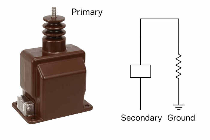
Connection Method / PT Connection
PT connection methods are strictly regulated, with core requirements as follows:
- Primary Side Connection: Connected in parallel with the high-voltage circuit under measurement. The PT must be selected based on its rated voltage (e.g., a 10kV/100V PT for a 10kV system). Incorrect voltage ratings must not be connected.
- Secondary Connection: Connected in series with metering instruments or relays. The total load of all connected devices must not exceed the PT's rated load (typically 5VA to 50VA).
- Polarity Marking: The primary and secondary sides are marked with "・" terminals, respectively. During wiring, ensure corresponding terminals with the same marking are connected. Failure to do so will cause phase errors, affecting measurement and protection accuracy.
- Grounding Requirements: One terminal on the secondary side must be reliably grounded. Grounding resistance should comply with substation grounding system specifications, typically ranging from 1–4Ω in standard projects, as determined by specific design codes. This prevents induced high voltages on the secondary side and ensures personnel safety.
Types of Potential Transformers
Types by Function (Metering PT, Protection PT)
PTs are categorized into two types based on function, with core differences in accuracy and response speed. Specific comparisons are as follows:
|
Type |
Metering PT |
Protection PT |
|
Core Requirements |
High metering accuracy with minimal error |
Rapid response, strong overload resistance |
|
Accuracy Class |
Class 0.1, Class 0.2, Class 0.5 (error ≤ ±0.1% to ±0.5%) |
Error limits for protection-grade PTs (e.g., 3P, 6P) must be measured at rated voltage and specified load conditions. Specific error requirements adhere to IEC/GB standards and cannot be described by a fixed percentage alone. |
|
Load Requirements |
Stable load, typically small |
Wide load range, capable of short-term overload |
|
Typical Applications |
Electricity metering cabinets, electricity billing devices |
Line protection, transformer protection relays |
By Construction / Types by Construction
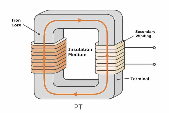
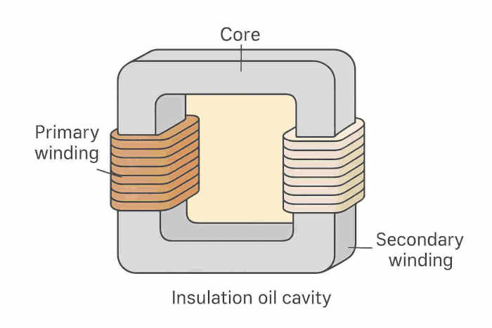
Electromagnetic PT
Electromagnetic PTs are the most traditional and commonly used type, consisting internally of an iron core and high/low voltage windings, with a structure similar to small power transformers.
Its advantages include high accuracy and stability, making it suitable for voltage levels of 35kV and below. Its disadvantages are large size, heavy weight, and relatively high cost in ultra-high voltage systems.
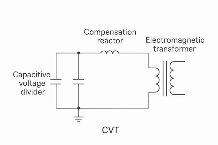
Capacitive PT / CVT
Capacitive PT (abbreviated as CVT) achieves voltage reduction through the capacitive voltage division principle. Its core components include a capacitive voltage divider, a compensating reactor, and an electromagnetic transformer.
- Operating Process: High voltage is first stepped down to an intermediate voltage via the capacitive divider, then converted to 100V low voltage through the electromagnetic transformer. The compensating reactor counteracts the capacitive reactance to ensure an accurate voltage ratio.
- Advantages: Compact size, lightweight, low cost, strong resistance to ferroresonance, suitable for ultra-high voltage systems of 110kV and above.
- Disadvantages: Generally, electromagnetic PTs offer superior power frequency measurement accuracy compared to CVTs. However, at voltage levels of 110kV and above, standard CVTs typically exhibit lower measurement accuracy than electromagnetic PTs. Only specially designed high-performance CVTs can achieve 0.2 or 0.2S accuracy at certain voltage levels, representing specific models rather than a common occurrence.
Other (e.g., Optical) / Optical VT
Optical VT operates based on electro-optic effects (e.g., Pockels effect), converting voltage signals into optical signals through photoelectric modulation, which are then transmitted via fiber optic cables to secondary equipment. It offers exceptional insulation performance and electromagnetic interference resistance.
Their advantages include exceptional insulation performance and strong resistance to electromagnetic interference, making them suitable for ultra-high voltage (e.g., 1000kV) systems.
Disadvantages include high cost and significant technical barriers, limiting current widespread adoption. As power systems evolve toward UHV and intelligent operation, optical VT applications will gradually expand.
Accuracy and Error Analysis
Error Types (Ratio Error, Phase Angle Error)
PT errors primarily fall into two categories, directly impacting measurement and protection accuracy:
- Ratio Error: The deviation between the actual voltage ratio and the rated ratio, caused by factors such as winding resistance, leakage reactance, and core losses. For example, in a PT with a rated ratio of 1000:1, if the actual secondary output is 99.8V (corresponding to a primary voltage of 99.8kV), while the true primary voltage is 100kV, this constitutes a ratio error.
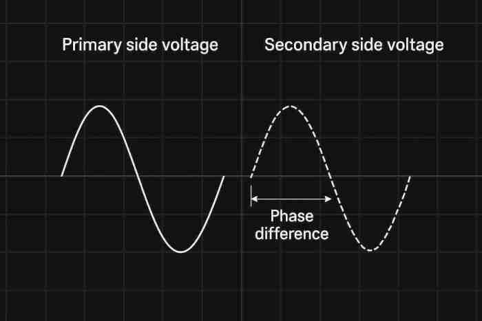
- Phase Angle Error: The phase difference between the primary voltage (after 180° reversal) and the secondary voltage, measured in minutes (1 degree = 60 minutes). Phase angle error affects phase-sensitive protection devices like distance protection, potentially causing false protection trips.

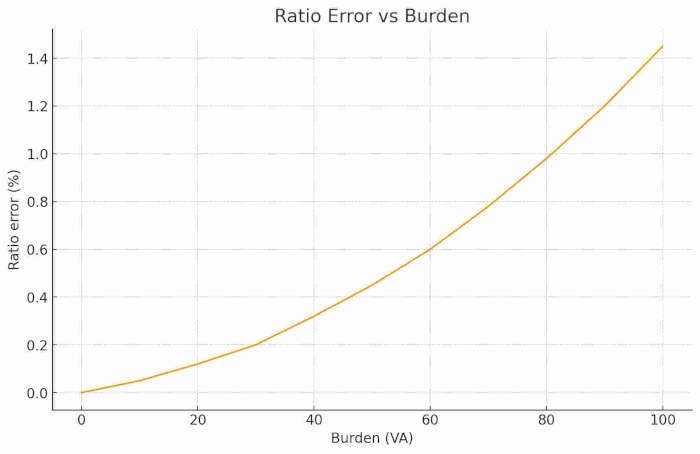
Burden and Accuracy Class
Burden: Refers to the total power of all equipment (meters, relays, cables) connected to the secondary side of the PT, measured in VA. Higher burdens result in greater errors; therefore, the PT's rated burden must exceed the actual total burden (a 20% margin is recommended).
Accuracy Class: Defined by IEC or ANSI standards. Common classes are listed in the table below:
|
Accuracy Class |
Ratio Error Tolerance Range |
Phase Angle Error Tolerance Range |
Applicable Scenarios |
|
Class 0.1 |
≤±0.1% |
≤±10 minutes |
High-precision metrology, laboratory equipment |
|
Class 0.2 |
≤±0.2% |
≤±20 points |
Industrial metering, electricity billing |
|
Class 0.5 |
≤±0.5% |
≤±30 points |
General measurement, monitoring instruments |
|
Class 3P |
≤±3% |
≤±30 points |
General relay protection |
|
6P Class |
≤±6% |
≤±60 points |
Backup Protection, Overload Protection |
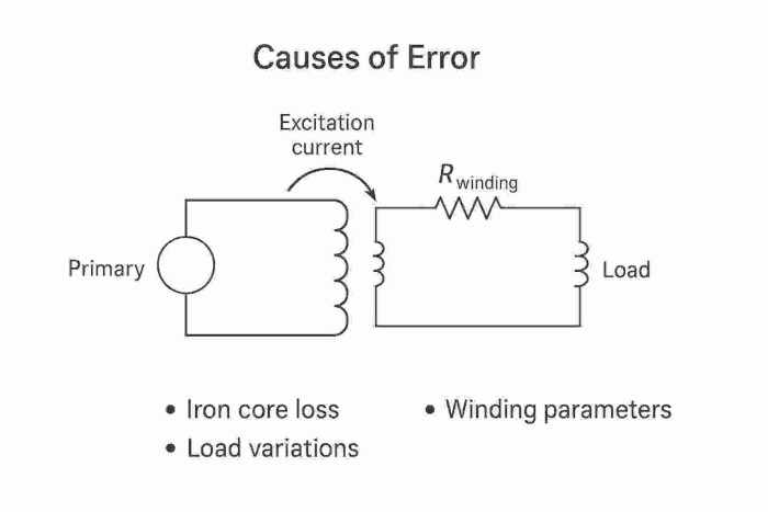
Causes of Error
PT errors primarily originate from three sources:
- Core losses: Hysteresis and eddy current losses in the core cause unstable magnetic flux, affecting the accuracy of the transformation ratio;
- Winding Parameters: Resistance and leakage reactance in windings cause voltage drops, resulting in reduced secondary output voltage;
- Load Variations: Exceeding the rated secondary load or changes in load characteristics (resistive, inductive, capacitive) disrupt magnetic coupling balance, increasing error.
Testing & Reading Potential Transformer
How to Read PT (Secondary Voltage, Phase)
Reading the PT output signal requires specialized instruments, with straightforward steps:
- Wiring Preparation: Connect the multimeter or oscilloscope probes to the PT secondary terminals (note polarity), ensuring the instrument's range is set for 100V AC voltage;
- Voltage Reading: Set the multimeter to the "ACV" range (select 200V range), then directly read the value. Under normal conditions, it should be approximately 100V (varying proportionally with the primary voltage);
- Phase Reading: Using a dual-trace oscilloscope, connect Channel 1 to the PT primary side (via a high-voltage probe) and Channel 2 to the secondary side. Observe the phase difference between the two waveforms. The normal phase difference should be close to 180° (when like terminals are correctly connected).
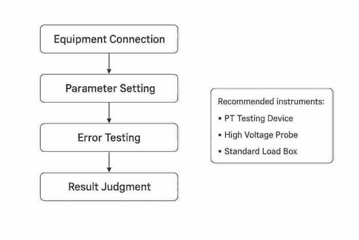
Calibration/Testing Method (Testing PT Accuracy)
PT accuracy calibration should follow these steps: a professional PT calibrator is recommended:
- Equipment Connection: Connect the calibrator's high-voltage output to the PT primary side and the PT secondary side to the calibrator's signal input. Simultaneously apply a standard load (matching the actual operating load).
- Parameter Setup: Input the PT's rated turns ratio, accuracy class, and other parameters into the calibrator.
- Error Testing: The calibrator outputs simulated high-voltage signals. Measure the PT's actual secondary output to automatically calculate the ratio error and phase angle error.
- Result Evaluation: If errors fall within the accuracy class tolerance range, the PT passes inspection. If errors exceed tolerance, inspect for winding damage, core saturation, or excessive load.
Common Wiring Configurations and Precautions
When wiring and using PTs, these points must be strictly observed to prevent safety incidents or equipment damage:
The primary side must be selected according to the rated voltage; connecting to the wrong voltage level is strictly prohibited (e.g., connecting a 10kV PT to 220kV high voltage will cause instantaneous burnout).
The secondary side must never be short-circuited. A fuse or miniature circuit breaker (rated current 2A–5A) must be connected in series to prevent winding burnout from short-circuit currents.
Polarity must not be reversed, as this causes phase errors, meter reversal, and protection device malfunctions.
One end of the secondary side must be reliably grounded. Grounding resistance values shall comply with local power industry design codes (typically within the range of 1 Ω to 4 Ω, but actual specifications shall prevail). This prevents induced high voltages on the secondary side.
After completing the wiring, use a multimeter to measure the secondary side voltage. Only connect the meter or relay after confirming no abnormalities.
Applications
Metering Applications
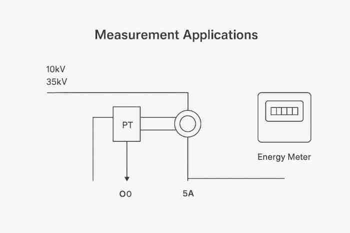
The core function of PTs in metering is "accurate voltage reduction," ensuring fair electricity billing. A typical application is industrial high-voltage metering cabinets: 10kV or 35kV high-voltage busbars are stepped down to 100V via PTs and fed into three-phase energy meters. Simultaneously, CTs (current transformers) convert high currents to 5A. The energy meters calculate electricity consumption based on voltage and current signals.
Protection / Protective Relaying
In protection scenarios, PTs supply voltage signals to relays for rapid fault identification. Examples include:
- Overvoltage Protection: When system voltage exceeds 1.2 times the rated value, the voltage signal from the PT triggers the overvoltage relay, disconnecting the line power to prevent equipment insulation breakdown.
- Undervoltage Protection: When system voltage falls below 0.8 times the rated value, the undervoltage relay is triggered to disconnect loads like motors, preventing equipment damage from low-voltage operation.
Power-Line Carrier Communication (PLC)
In Power-Line Carrier (PLC) systems, the actual high-frequency communication coupling functions are performed by coupling capacitors (CC) and high-frequency line traps. Voltage transformers (PT) themselves do not possess high-frequency coupling capabilities; only certain capacitive voltage transformer (CVT) models feature high-frequency terminals suitable for high-frequency carrier communication. Communication signals (such as high-frequency carrier signals) are superimposed onto high-voltage lines via couplers. The PT, in conjunction with filters, extracts these signals from the high-voltage lines and transmits them to communication equipment while isolating the high voltage to protect the safety of the communication equipment.
This application is common in remote area power communications, eliminating the need for additional communication line installation and reducing construction costs.
Other (Industrial Monitoring, Power Automation)
Beyond core applications, PTs are widely used in industrial monitoring and power automation systems:
- Industrial Monitoring: PTs collect voltage data from high-voltage equipment and upload it in real-time to monitoring platforms, enabling engineers to remotely monitor equipment status.
- Power Automation: In smart substations, PT voltage signals feed into automation control systems to enable functions like automatic voltage regulation and fault isolation, enhancing the intelligence of power systems.
Selection & Procurement Guide
How to Select PT
PT selection should follow a "purpose-driven" approach, proceeding as follows:
- Determine Voltage Rating: Match primary voltage to system voltage (e.g., select 10kV/100V PT for a 10kV system). Prioritize 100V for secondary voltage (domestic standard).
- Select functional type: Choose 0.1/0.2 class for metering applications, 3P/6P class for protection applications, or dual-class (e.g., 0.2/3P) for combined metering and protection;
- Calculate rated load: Sum the power of all secondary-side equipment. The PT's rated load must be ≥ total load × 1.2 (reserving a 20% margin);
- Determine structure type: Electromagnetic PT for 35kV and below; CVT for 110kV and above; optical VT for UHV scenarios;
- Adapt to environmental conditions: Select oil-immersed or SF6 gas-insulated PTs for outdoor use; choose dry-type PTs for indoor use; opt for low-temperature PTs (oil freezing point ≤ -40°C) in cold regions.
Recommendations for Replacement and Spare Parts
When the original PT model is discontinued or unavailable, replacement parts must meet the following criteria:
- Rated voltage and transformation ratio must match the original model, and the accuracy class must not be lower than the original model.
- Rated load ≥ original model; installation dimensions and wiring methods are compatible;
- Structural type and insulation rating must match the operating environment (e.g., outdoor replacements require waterproof and dustproof capabilities).
Spare Parts Stocking Recommendations: Maintain core spare parts at 10% of equipment quantity, prioritizing high-wear components (e.g., fuses, terminal blocks). Store spare parts in dry, well-ventilated environments and conduct regular insulation performance checks.
Safety & Maintenance
PT (Voltage Transformer) High-Voltage Operation Safety Specifications
- Core Operational Procedures
-
- Personal Protection: Certified personnel only. Wear ≥10kV insulated gloves and insulated footwear throughout the operation. Use qualified insulated tools.
- Power Disconnection & Discharge: Before wiring/maintenance, disconnect the primary high-voltage power supply. Use grounding rods to discharge both primary and secondary sides (≥30 seconds). Verify the absence of voltage before proceeding.
- Operational Prohibitions: Strictly prohibit opening covers during operation; prevent secondary-side short circuits; regularly inspect secondary-side fuses for integrity.
- Personal Protection: Certified personnel only. Wear ≥10kV insulated gloves and insulated footwear throughout the operation. Use qualified insulated tools.
- Safety Warning
-
 High Voltage Hazard, Certified Operation Only
- Must Ground and Discharge Before Operation
- Secondary Side Short-Circuit Strictly Prohibited
- Additional Requirements
-
- Weekly inspection of PT appearance and grounding device; shut down immediately if abnormalities are detected.
- Immediately de-energize upon fault (e.g., smoke, abnormal noise), discharge, then investigate.
- Conduct safety training at least twice annually.
- Weekly inspection of PT appearance and grounding device; shut down immediately if abnormalities are detected.
- International Safety Standard Reference: The safety requirements for PT (Potential Transformer) supporting power electronic protection devices and converter systems shall comply with IEC 62477-1 (including its revised versions).
Calibration Cycle and Maintenance Recommendations
PT maintenance must be performed regularly to ensure accuracy and stability:
- Calibration Intervals: - Metering PTs: Calibrate annually. - Protective PTs: Calibrate every 2 years. - Shorten intervals in harsh environments (e.g., high temperature, high humidity).
- Routine Maintenance: Monthly inspection for loose connections, oil leaks, or abnormal noises; clean surface dust.
- Periodic Testing: Annually measure winding insulation resistance (≥100MΩ) using a megohmmeter. For oil-immersed PTs, test oil quality (breakdown voltage ≥30kV).
- Fault Handling: Immediately cease operation upon detecting measurement errors exceeding tolerance, decreased insulation resistance, or oil leakage. Contact qualified personnel for repair or replacement.
Maintenance Form Recommendations: Develop a maintenance schedule template including columns for maintenance items, cycles, standard requirements, and responsible personnel.
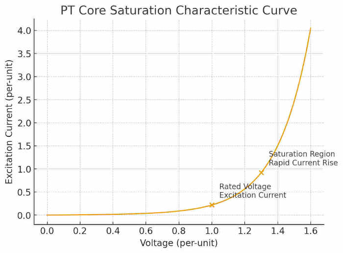
Risks of Saturation and Over-Excitation
Saturation or overexcitation of the PT core can cause errors to increase sharply or even cause the equipment to burn out. Key precautions include:
Causes of over-excitation: Excessively high primary voltage (e.g., exceeding 1.3 times rated voltage) or abnormally low frequency.
Note: Under normal operation, PTs inherently operate near no-load conditions. Secondary no-load operation does not cause core saturation nor generate hazardous voltages like CTs. No-load operation of PTs is safe and normal.
The primary causes of PT core saturation are excessively high primary voltage, system over-excitation, or ferroresonance. This is not directly related to the magnitude of the secondary load.
Conclusion & Outlook
Key Takeaways
The core function of PTs is "voltage reduction + isolation," converting high voltage to the standard 100V low voltage for metering and protection equipment.
Classified by function into metering-type (high precision) and protection-type (fast response), and by structure into electromagnetic, capacitive, and optical types;
Errors primarily include ratio error and phase angle error, influenced by load, winding parameters, and core losses.
Selection requires matching voltage levels, accuracy grades, and load requirements; operation and maintenance must adhere to high-voltage safety standards.
Future Trends
As power systems evolve toward ultra-high voltage, intelligent, and green technologies, PT development trends focus on three key directions:
- Intelligentization: Integrating sensors and communication modules to enable online error monitoring and remote calibration, adapting to automation requirements in smart substations;
- Miniaturization: Utilizing new materials and structural designs to reduce size and weight, lowering installation and transportation costs;
- Environmental Sustainability: Dry-type PTs and SF6-free eco-friendly PTs are gradually replacing oil-immersed PTs to minimize environmental pollution.
Frequently Asked Questions (FAQ)
What is the difference between a transformer and a voltage transformer?
The core distinction lies in their purpose and operating conditions: Transformers transmit electrical power under load, prioritizing transmission efficiency; PTs measure voltage and provide protection, operating near no-load conditions, emphasizing accuracy and isolation performance—secondary-side short circuits are strictly prohibited.
How does a VT work?
Based on electromagnetic induction: The primary winding carries high voltage, generating alternating magnetic flux. The secondary winding induces a proportionally lower voltage, with the transformation ratio determined by the turns ratio (Vp/Vs = Np/Ns), simultaneously achieving high-low voltage isolation.
What is the difference between a Current Transformer (CT) and a Potential Transformer (PT)?
CTs are used for high-current transformation (e.g., 1000A → 5A), with the secondary side operating near short-circuit conditions; open circuits are strictly prohibited. PTs are used for high-voltage transformation (e.g., 10kV → 100V), with the secondary side operating near no-load conditions; short circuits are strictly prohibited. Their core applications and safety restrictions are fundamentally different.
How do you read the output of a voltage transformer?
Connect a multimeter set to the AC voltage range (200V scale) to the PT secondary side. Expected output should be approximately 100V. To read the phase, use a dual-trace oscilloscope to compare the phase difference between primary and secondary waveforms.