Karman Vortex MAF Sensor: Pros, Cons, and Applications
| Table of Contents |
Fundamentals & Principle
The Karman vortex mass air flow (MAF) sensor serves as an ingenious bridge between classical fluid dynamics and modern automotive engine control systems. Rather than directly measuring the airʼs physical properties(e.g., thermal conductivity or cooling effects), it captures the Karman vortex street—a natural physical phenomenon formed by airflow under specific conditions—transforming invisible air movement into a precisely measurable digital frequency signal. This operating mechanism,
What Is a Karman Vortex MAF Sensor?
The von Karman vortex street is a classic flow phenomenon in fluid dynamics. When a viscous fluid flows around a blunt body (such as a cylinder) within a specific Reynolds number range, a series of vortices with alternating rotation directions and regular arrangement form downstream of the body. These vortices are shed at a fixed frequency, forming a continuous vortex street. Under stable flow conditions, the shedding frequency of these vortices exhibits a definite regularity, a characteristic that forms the core physical basis for flow measurement. The Karman Vortex MAF (Mass Air Flow) sensor utilizes this phenomenon. By detecting the frequency of the Karman vortex street generated in the intake airflow, it indirectly calculates the engine's intake air volume.

For technical readers, the vortex shedding frequency of the Karman vortex street exhibits a clear quantitative relationship with fluid velocity, defined by the core formula: f = St · V / d
Where: f is the vortex shedding frequency (unit: Hz); St is the Strouhal number, a dimensionless constant related to flow characteristics (e.g., fluid viscosity and compressibility) and the shape of the vortex generator. For a specific sensor design, St is a fixed value; V is the fluid (intake) velocity (unit: m/s); d is the characteristic dimension of the vortex generator (e.g., cylinder diameter, unit: m). By measuring the frequency f and combining it with the known values of St and d, the intake air velocity can be calculated. Integrating this with the cross-sectional area of the intake duct yields the intake air flow rate.
Working Principle and Signal Output
The operation of the Karman vortex air flow sensor originates from a classic fluid dynamics phenomenon. When air flows past the vortex generator inside the sensor, it forms a series of regularly shed vortices whose frequency is proportional to the flow velocity. The sensor optically captures this frequency and ultimately outputs a corresponding digital square wave signal for precise ECU calculations. Taking the Karman Vortex MAF sensor used in Toyota vehicles as an example:
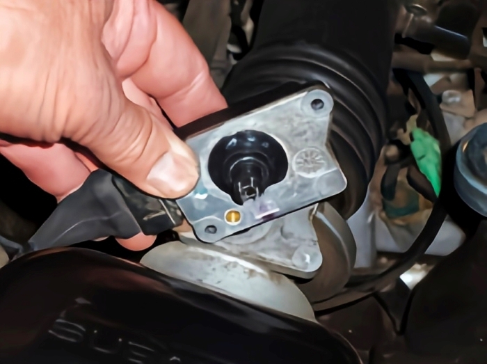
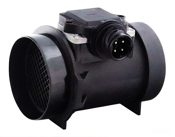
Toyota's design for airflow measurement within its engine management system is uniquely representative. Unlike most manufacturers using thermal film or hot-wire mass air flow sensors (MAF), Toyota employs Karman vortex-based MAFs across multiple engine platforms. This solution typically features a 5-pin layout (subject to adjustments by model and year), incorporating both airflow detection circuitry and a separate intake air temperature (IAT) sensor circuit.
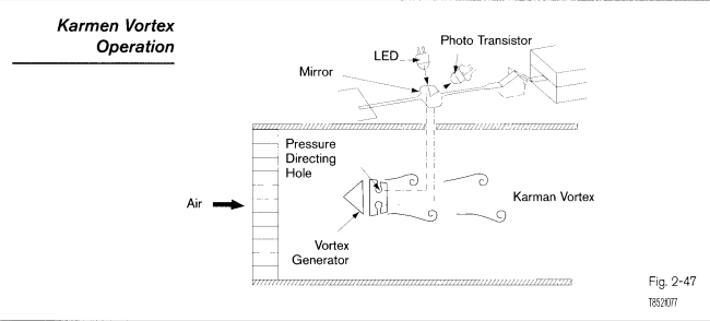
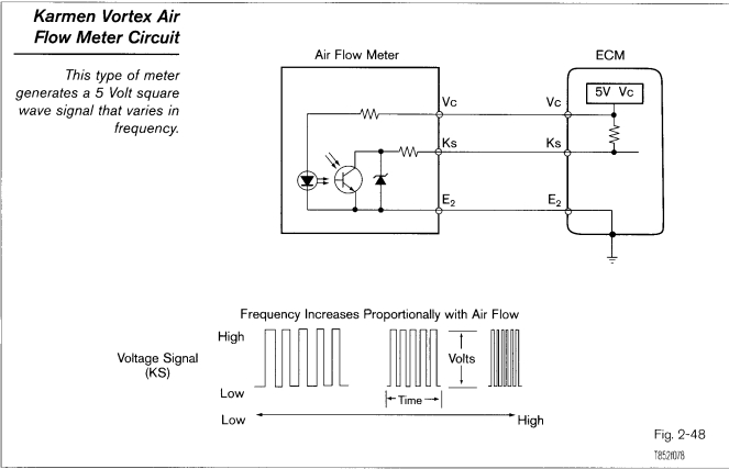
Inside the Karman vortex sensor, a vortex generator is positioned within the intake duct. As air flows at high velocity, a pair of alternating vortex rows detaches from the wake region, forming the characteristic Karman vortex street. The frequency of these vortex shedding events exhibits a linear relationship with airflow velocity. The sensor digitally samples the vortex street using light-emitting diodes (LEDs) and photosensitive elements, converting the vortex shedding rate into a pulse signal of the same frequency. This output is not an analog voltage but a digital square-wave signal with an amplitude of approximately 0–5 V, whose frequency directly corresponds to the airflow rate.
Unlike thermal MAFs, the Karman vortex method measures flow-dependent frequency characteristics determined by fluid dynamics. This avoids compensation calculations related to thermal conduction and heat capacity, making it less sensitive to contamination, aging, or humidity. The ECU stores pre-calibrated flow curves internally, enabling direct conversion of real-time pulse frequency into intake volume flow. Combined with temperature, pressure, and other data, this facilitates mass flow estimation.
This digital frequency-measurement method offers several advantages,
Frequency Characteristics & Waveform Analysis
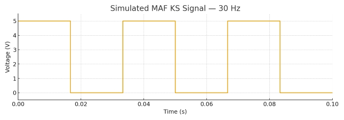
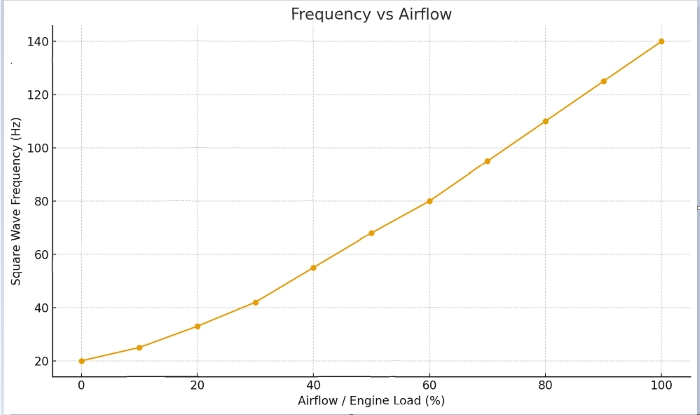
The output signal from a Karman vortex street MAF sensor is a pure frequency signal. This ensures exceptional signal stability, strong interference resistance, and a highly linear relationship with airflow. The output signal is a square wave where the frequency is directly proportional to airflow. At idle, the output frequency is typically around 30–40 Hz, while under high load, it can exceed 140–160 Hz on many 2.0–3.0 L Japanese gasoline engines. The voltage amplitude remains constant at 5V peak-to-peak; only the frequency varies (number of pulses per unit time).
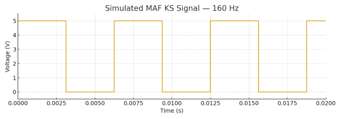
The core logic of this frequency characteristic stems from the physical principles of the Karman vortex street: with the sensor structure fixed (St and d constant), the vortex shedding frequency f is directly proportional to the intake air velocity V. Since the intake air flow rate is the product of velocity and the cross-sectional area of the intake duct (ignoring temperature and pressure corrections), thus establishing a strict linear positive correlation between frequency f and airflow rate—higher frequencies indicate faster vortex shedding, greater airflow velocity, and correspondingly higher airflow volume.
The ECU processes this signal as follows: First, it detects the square wave frequency input via the KS signal line using an internal timer. Combining this with the sensor's preset St and d values and intake duct parameters, it calculates the real-time intake air velocity. Then, integrating the temperature signal transmitted by the intake air temperature sensor (to correct for air density), it precisely calculates the mass flow rate of air entering the engine. Based on this flow data, the ECU calculates the required fuel injection volume according to the air-fuel ratio theory (typically the ideal 14.7:1 air-fuel ratio), achieving precise fuel injection calibration to balance engine power performance and fuel economy.
Advantages & Disadvantages
To comprehensively analyze the technical characteristics of the Karman vortex sensor, the following discussion will explore its advantages and disadvantages. Through performance comparisons, principal analysis, and practical case studies, we will clearly present its technical strengths and limitations, as well as its application boundaries.
Advantages of Karman Vortex MAF Sensor
To clearly position the Karman vortex sensor technologically, the following table compares its core performance differences with two mainstream MAF sensor types—hot-wire and blade-type—before analyzing its unique advantages and OEM application logic.
Table Comparison: Karman Vortex vs. Other MAF Sensor Types
|
Performance Dimension |
Karman Vortex |
Hot-wire |
Blade-Type |
|
Stability |
Stable frequency output, strong noise immunity |
Sensitive to temperature changes, requiring ECU compensation |
Deviations occur due to wear and a change in spring characteristics |
|
Mechanical wear |
No mechanical moving parts, no contact wear |
No mechanical wear, but carbon deposits may accumulate |
Mechanical structure present; spring fatigue and wear |
|
Response time |
Quickly responds to flow changes |
Fast response, but affected by the heating element's thermal inertia |
Slow, dependent on physical baffle movement |
|
Contamination resistance |
Relies |
Heating wire is highly susceptible to oil mist contamination |
Damping may increase due to dust accumulation |
|
Cost |
Moderate |
Higher manufacturing cost |
Lower cost but shorter lifespan |
• No Mechanical Moving Parts: The sensor's core operation relies on vortex shedding and photoelectric conversion, eliminating moving structures like blades or shafts. This fundamentally prevents mechanical wear and failure modes inherent to moving parts, such as jamming and other failures, thereby reducing maintenance frequency.
• Stable and reliable frequency output: The output 5V square wave frequency exhibits a strict linear relationship with airflow, featuring strong signal interference resistance. The ECU can accurately calculate air intake volume without complex corrections upon reception, enhancing fuel control precision.
• Low intake resistance: Requires only a compact vortex generator within the intake duct, significantly reducing airflow obstruction compared to vane-type sensors. This minimizes engine intake losses and supports optimal power delivery.
• Long lifespan without heating: Free from mechanical wear and resistant to contamination, it operates without heating wires or thermal films, eliminating risks of carbonization or ablation. This ensures high long-term operational reliability.
Taking Toyota as an example, the adoption of Karman vortex air flow sensors in its turbocharged and large-displacement naturally aspirated engine platforms represents a critical engineering decision ensuring high performance and reliability. Compared to traditional hot-wire/hot-film sensors, their technical advantages are particularly prominent in such demanding applications.
First, exceptional linearity and low flow resistance form its core strengths. The Karman vortex sensor maintains an outstanding linear relationship between frequency signal and air velocity across the entire flow range—from idle to high RPM and heavy load conditions. This provides the ECU with highly precise air intake data, forming the foundation for accurate air-fuel ratio control. Simultaneously, its internal vortex generator structure imposes significantly less resistance to airflow than hot-wire sensors, which require protective grids for delicate thermal elements. This results in significantly lower intake resistance for the Karman sensor. This is critical for turbocharged systems, reducing pumping losses and enhancing boost efficiency and engine responsiveness.
Second, its robust tolerance to harsh operating conditions significantly enhances long-term reliability. Since the sensor detects vortex frequency via optical or ultrasonic principles, its core measurement element avoids direct contact with the intake air and does not rely on heat exchange. This characteristic makes it far less sensitive to oil mist and dust
Consequently, the Karman vortex sensor demonstrates exceptional performance in long-term durability testing and extended maintenance intervals, exhibiting a significantly lower performance degradation rate than traditional hot-wire MAFs. This makes it an attractive choice
Disadvantages of Karman Vortex MAF Sensor
Despite the Karman vortex sensor's outstanding stability and durability, no technological solution is flawless. Its unique operating principle and intricate internal structure introduce inherent limitations and specific maintenance challenges. Understanding these disadvantages is crucial for the proper use, diagnosis, and maintenance of this component.
• Cannot be cleaned arbitrarily: Internal components like the metal reflector and photosensitive elements are sensitive to chemical solvents. Using MAF cleaners, alcohol, or similar substances during cleaning can corrode the mirror surface or damage seals, leading to signal distortion.
• Prone to frequency drift over time: Long-term exposure to airflow may cause minor deformation of the vortex generator, or aging of photoelectric components, shifting the Strouhal number (St) and disrupting the calibration between frequency and flow rate.
• Poor response at low temperatures and low flow rates: During engine idle or cold starts with low intake airflow, irregular vortex formation causes unstable frequency signals. This may result in brief fuel injection deviations, manifesting as idle speed fluctuations.
• Susceptible to connector corrosion: If the KS signal line connector to the ECU is corroded by moisture or oil contamination, poor contact may occur. This can interrupt or distort frequency signal transmission, triggering the engine malfunction indicator light.
Below is a real-life case shared by a user on a forum regarding cleaning a Karman vortex MAF sensor." NEVER clean Karman vortex sensors with MAF cleaner! Last week, I cleaned the sensor on my Toyota Camry to fix an idle issue. After spraying, the engine stalled immediately. The dealership inspection revealed that the reflector was corroded by the solvent, causing scratches that prevented proper light reflection. The only solution was to replace the sensor. Multiple forum members have reported similar experiences. Currently, there is no reliable cleaning method, and any attempt may render the sensor inoperable ."
Applications & OEM Usage
This section focuses on its practical applications and development trajectory, covering mainstream compatible models, industry application history, and OEM technological evolution, clearly illustrating its shifting role within the automotive industry.
Which Cars Have a Karman Vortex MAF Sensor?
The Karman vortex MAF sensor is predominantly used in Japanese high-performance and premium vehicles, with Toyota, Lexus, and Mitsubishi as key adopters. The engine models and vehicle types it equips bear distinct generational characteristics, as detailed in the table below.
|
Manufacturer |
Brand and Models |
Engine Model |
Years of Use |
Core Compatibility Reason |
|
Toyota |
Toyota Celica XX A60 |
5M-GE (3.0L naturally aspirated) |
1982-1986 |
First mass-produced adaptation, replacing blade-type components to resolve wear issues |
|
Toyota |
Toyota Supra A70 |
7M-GTE (3.0L Turbocharged) |
1986–1992 |
Low-inlet-resistance turbocharger adaptation enhances high-speed power response |
|
Toyota |
Toyota Crown S133/S141 |
1JZ-GTE (2.5L Turbocharged) |
1990-1995 |
Luxury models demand signal stability and extended lifespan |
|
Lexus |
Lexus LS400 UCF10 |
1UZ-FE (4.0L naturally aspirated) |
1989-1994 |
Flagship models require precise air-fuel ratio control, with significant advantages in linear output |
|
Lexus |
Lexus GS300 S141 |
2JZ-GE (3.0L naturally aspirated) |
1993–1997 |
Sport-luxury positioning, balancing power response and reliability |
|
Mitsubishi |
Mitsubishi Lancer EVO III-V |
4G63T (2.0L Turbocharged) |
1995–1998 |
Racing-tuned for high-rev turbocharger performance |
|
Mitsubishi |
Mitsubishi Pajero V31/V33 |
6G72 (3.0L Supercharged/Naturally Aspirated) |
1991-2000 |
Off-road vehicle extreme environment endurance requirements |
Application Timeline in the Automotive Industry
•1982 - Mass Production Breakthrough: Toyota first achieved mass production of the Karman vortex MAF sensor on the 5M-GE engine in the Celica XX A60, replacing traditional vane-type sensors. This solved the idle instability caused by vane wear. Bench and field tests reported service
life exceeding approximately 80,000 km under typical operating
•1989-1995 - High-End & Performance Penetration: Following Lexus' launch, it became standard on the flagship LS400. Toyota concurrently applied it to performance models like the Supra; Mitsubishi followed suit for the EVO series, establishing a technical consensus among Japanese manufacturers.
•1996-2005: Scenario Segmentation Expansion: Extended from gasoline engines to diesel variants (e.g., Toyota 1 HZ). Ultrasonic detection technology upgrades addressed cold-start responsiveness limitations, though market presence gradually contracted in economy-class family vehicles.
•2006–Present: Market Persistence: Replaced by thermoelectric sensors in mainstream passenger vehicles, yet persists in diesel commercial vehicles, hardcore off-roaders, and aftermarket markets. Examples include Toyota Land Cruiser LC70 series models still utilizing this sensor type.
Major OEM Development Timeline
•1978-1981 - Technology R&D Phase (Toyota): Toyota Central R&D Labs collaborated with DENSO to initiate development of the Karman vortex flow sensor, targeting the "wear-induced accuracy degradation" issue of vane-type sensors. Bench testing completed in 1981.
•1982-1988 - Toyota's Exclusive Application Period: Deployment expanded from the Celica XX to flagship models like the Crown and Supra. According to the 1985 Toyota Engine Technology Annual Report, this sensor improved air-fuel ratio control accuracy from approximately ±5% to about ±2% in their test platforms.
•1989-1998 - Multi-Manufacturer Adoption Phase: Lexus positioned it as a signature brand technology. Mitsubishi adapted it for the EVO series through technology licensing. Nissan briefly tested it in select premium models (e.g., 300ZX Z32), forming a Japanese manufacturer technology cluster.
•1999-2005 - Optimization and Differentiation Phase: Toyota introduced an upgraded ultrasonic detection version (replacing optical detection), while Mitsubishi optimized turbine body structures for turbocharged conditions. Concurrently, European and American manufacturers (like Bosch) primarily promoted thermal film sensors, creating divergent technical paths.
•2006–Present - Replacement and Retention Phase: Toyota switched mainstream models like the Camry and Corolla to thermal film sensors, retaining ultrasonic sensors only for specialized models like the Land Cruiser and Hilux. Mitsubishi abandoned the technology after the EVO X, while Kamen Vortex retreated to commercial vehicle and off-road niche markets.
OEM Selection Logic & Document Citation
• Japanese manufacturers' core rationale for selecting Karman vortex sensors centers on "low resistance, high reliability, and suitability for specific operating conditions." Toyota's Engine Control System Design Specifications (1990 Edition) explicitly states: The intake resistance of Karman vortex sensors is only 18% that of vane-type sensors and 45% that of hot-wire sensors, enabling a 3%-5% improvement in intake efficiency for turbocharged engines. Its volume is 40% smaller than hot-wire sensors, meeting the compact layout requirements of engine compartments."
• Mitsubishi's 4G63T Engine Technical Manual adds: "This sensor contains no moving mechanical parts. At high RPM 7000 rpm+), signal fluctuation remains ≤2%, significantly outperforming vane-type sensors (8%). It accommodates race-tuned power settings while exhibiting strong tolerance to oil vapor in intake air, resolving sensor contamination issues caused by inefficient oil-gas separators in turbocharged vehicles."
• Lexus emphasized in its LS400 development documentation (UCF10 Project Report): "Flagship models require over 100,000 km of fault-free operation. The Karman vortex sensor demonstrated only a 3% performance degradation rate after 150,000 km, compared to 12% for hot-wire sensors during the same period. This reliability advantage directly underpins the brand's luxury positioning."
Technical Trend Analysis & Future Outlook
• Modern Replacement Trends: As ECU computational power increases and the cost of MAP (Manifold Absolute Pressure) + oxygen sensor combinations decreases, mainstream passenger vehicles have largely replaced MAF sensors with this combination. MAP indirectly calculates airflow by detecting intake manifold pressure, offering a simpler structure and stronger contamination resistance, while meeting stringent emission regulations like China VI and beyond.
• Future Retention Scenarios: Karman vortex sensors remain irreplaceable in commercial vehicles (diesel trucks, buses) and hardcore off-road vehicles. Under commercial applications' high-dust, high-vibration conditions, field reports indicate a significantly longer service life
than thermal‑film sensors, in some high-dust diesel applications reaching two to three times the typical lifetime. For off-road vehicles operating in low-temperature, low-RPM conditions, their flow detection accuracy outperforms the MAP combination.Additionally, in the aftermarket (e.g., high-horsepower turbocharged race cars), their high-RPM stability remains highly valued, posing no immediate risk of complete market withdrawal.
Diagnostics & Faults
This section focuses on core diagnostics and fault resolution. Mastering failure modes, diagnostic methods, and troubleshooting strategies is essential for ensuring stable engine operation and pinpointing issues.
Common Failure Modes
Failures in Karman vortex sensors are often related to signal transmission, core component damage, and connection issues . Data from SignalAutoParts' MAF Sensor Diagnostic Manual and automotive repair forums indicates that approximately 70% of faults can be identified through signal detection and physical inspection. Typical failure modes and case examples include:
• Idle instability/shuddering: Caused by irregular vortex formation or signal drift during low airflow, leading to ECU fuel injection deviation. As reported by a Reddit user: "Toyota Land Cruiser idled at 600-800 rpm fluctuations. Inspection revealed sensor frequency jumping between 25-35 Hz. Replacing the sensor restored stability."
• Stall during acceleration/power loss: High-frequency signal interruptions or distortion prevent the ECU from recognizing high-flow demands. SignalAutoParts documented: "Mitsubishi EVO IV stalled during rapid acceleration to 5000 rpm. Inspection revealed vortex generator deformation, limiting frequency to 120 Hz (normal range is 160 Hz)."
• Frequency signal interruption: Often caused by loose connectors or burnt-out photosensors. Workshop case: "Lexus LS400 displayed engine fault light. The fault vanished after unplugging the sensor connector. Teardown revealed oxidized pins causing poor contact."
• Connector corrosion failure: Moisture intrusion causes signal short circuits, common in rainy regions. Forum user case: "Camry sensor connector contained internal water accumulation. Measured 1V noise on signal wires. Functionality restored after cleaning and applying conductive grease."
Diagnostic Methods
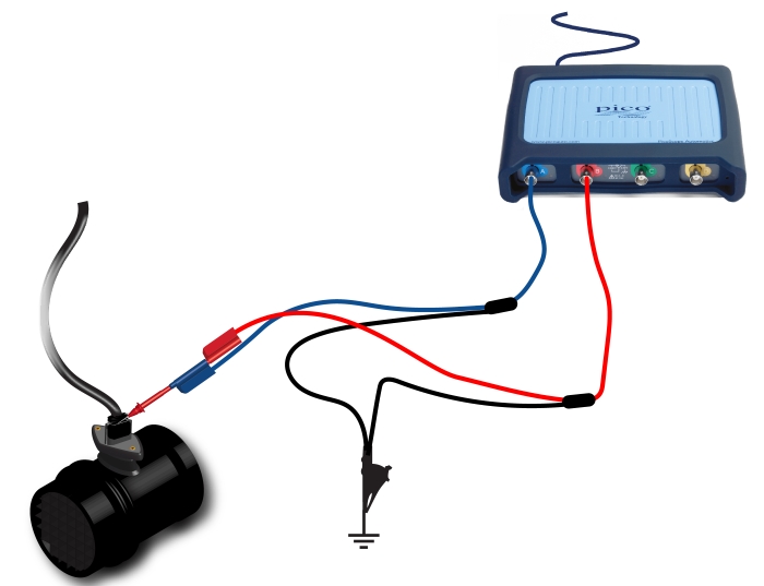
• Practical Guide to Oscilloscope Procedures (Referencing Pico Digital MAF Testing Process)
1. Prepare Tools: Digital oscilloscope (bandwidth ≥10MHz), back-probing needles (probes), grounding wire, and insulating tape. Ensure the engine is in a cold state.
2. Connect wiring: ① Locate the KS signal wire (typically pin 3 for Toyota, pin 2 for Mitsubishi). Pierce the wire insulation with a back-piercing probe and connect to Oscilloscope Channel 1. ② Connect the oscilloscope ground lead to the engine block ground point.③ Set oscilloscope parameters: Time base 5ms/div, voltage range 5V/div, trigger mode "Rising Edge Trigger", trigger level 2.5V.
3. Signal Acquisition: ① Start engine to idle and capture 30 seconds of signal; ② Slowly depress throttle to 3000 rpm (medium load) and continue capturing; ③ Rapidly accelerate to 5000 rpm (high load) and capture transient signal; ④ Shut off engine and save waveform data.
4. Data Comparison: Export waveforms and compare with standard data, focusing on frequency variation, amplitude, and stability analysis.
• Typical Waveform and Parameter Description
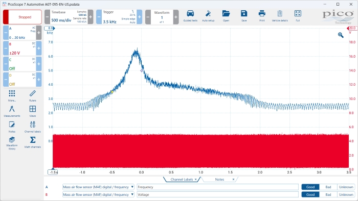
1. Linear Variation Check: Plot a "RPM-Frequency" curve. A normal curve should be nearly linear. If the frequency stalls or abruptly changes within a certain range (e.g., dropping sharply from 80 Hz to 40 Hz during acceleration), it indicates sensor or signal transmission issues.
2. Connection Troubleshooting: Disconnect the connector and measure resistance between pins with a multimeter (check for shorts between power and ground; signal line resistance to ground typically > 1MΩ). Clean oxidized pins with fine sandpaper and apply conductive grease.
3. Fault Code Correlation: If the ECU stores related fault codes, combine waveform inspection to avoid misdiagnosis based solely on codes (e.g., wiring harness issues may trigger "Sensor Fault" codes).
Fault Codes & Real-World Cases
• Common Fault Codes and Corresponding Causes (Refer to SignalAutoParts Diagnostic Manual).
|
Manufacturer |
Fault Code |
Fault Code Description |
Root Cause |
|
Toyota |
P0100 |
Mass Air Flow (MAF) Sensor Circuit Malfunction |
Signal wire open/short circuit, ECU power supply abnormality |
|
Toyota |
P0102 |
Low MAF Sensor Signal |
Mirror contamination, turbocharger carbon buildup, and poor grounding |
|
Toyota |
P0103 |
High MAF Sensor Signal |
Photoelectric component aging, connector pin short circuit |
|
Mitsubishi |
P0171 |
Fuel system lean (correlated with MAF) |
Low MAF signal, intake air leak |
|
Mitsubishi |
P1105 |
MAF Sensor Frequency Abnormal |
Turbocharger housing deformation, internal sensor circuit failure |
• Real-world case descriptions
Case 1: Sensor failure caused by cleaning: "Mitsubishi Pajero experienced idle vibration, read fault code P1105. After seeing forum posts suggesting cleaning could fix it, I sprayed the sensor with MAF cleaner. After reinstalling, the engine stalled immediately. The oscilloscope showed no frequency signal. The dealership claimed the reflector was corroded and insisted on replacing the entire sensor for 800 yuan—remember: vortex sensors must never be cleaned with solvents!"
Case 2: Hidden Connector Corrosion: "Toyota Supra exhibited sluggish acceleration with fault code P0100. Visual inspection of the sensor showed no abnormalities. The power line measured 12V voltage, but the signal line showed no frequency. Upon disassembling the connector, green copper corrosion was found on the pins. After cleaning with alcohol swabs and reassembly, the frequency rose to 150 Hz during acceleration, resolving the issue. The entire process took less than 10 minutes."
• Repair Tips
Maintenance & Cleaning
The core challenge in maintaining Karman vortex sensors lies in the conflict between "cleaning necessity" and "component sensitivity." Previous fault cases have demonstrated the severe consequences of improper cleaning. This chapter systematically explains cleaning feasibility, safe operation procedures, and risk mitigation strategies.
Can You Clean a Karman Vortex MAF Sensor?
Based on technical principles and manufacturer specifications, standard MAF cleaning sprays or chemical solvents are generally not recommended for cleaning Karman vortex sensors.SignalAutoParts' MAF Sensor Maintenance Manual explicitly states: "This sensor type incorporates a metal reflector (aluminum-coated surface) and a photosensitive transistor, which are highly sensitive to hydrocarbon solvents (such as isopropyl alcohol and ethanol found in MAF cleaners). Solvent contact causes irreversible damage, including corrosion of the reflector coating and parameter drift in the photosensitive components."
User experiences within automotive repair communities further validate this conclusion. A highly upvoted response on Reddit's Auto Repair subreddit states: " There is currently no widely
Comparison of Commonly Used Cleaning Agents
|
Cleaning Agent Type |
Karman Vortex Type Risk |
Hot-wire Type Applicability |
Notes |
|
MAF-Specific Cleaning Spray |
Extremely High (Mirror Film Layer Corrosion, Seal Failure) |
Suitable (dissolves carbon deposits without damaging heating wire) |
Standard cleaning tool for hot wire type; strictly prohibited for K arm a n type |
|
Isopropyl Alcohol (99%) |
High (Corrosion of photosensitive component pins, mirror haze) |
Use with caution (requires rapid air-drying to prevent residue) |
Some heating element types may be briefly soaked; absolutely prohibited for K arm a n types |
|
Low-pressure compressed air (≤0.2 MPa) |
Low (only suitable for surface dust removal) |
Suitable (for blowing off surface dust from hot wires) |
The only acceptable cleaning method for K arm an-type |
|
Distilled water (room temperature) |
Moderate (may cause internal circuit moisture and short circuits) |
Prohibited (heating element prone to oxidation when exposed to water) |
For K arm a n models, only use for cleaning the exterior casing; ensure thorough air-drying |
Safe Maintenance Tips
The core principle for maintaining Karman vortex sensors is "inspection instead of cleaning, prevention instead of repair." Safe operation procedures and precautions are as follows:
• Power Disconnection Precondition: Before maintenance, disconnect the vehicle battery's negative terminal (wait 3 minutes to ensure ECU discharge) to prevent electrical sparks during connector insertion/removal that could damage sensor circuits.
• Proper Connector Handling: Grasp the connector latch (never pull the wires) and insert/remove vertically. After removal, use compressed air to blow out internal dust. For oxidized pins, gently wipe with a small amount of conductive grease (never use sandpaper).
• Key Visual Inspection Points: ① Check if the intake-side filter mesh is damaged (replace sensor if damaged to prevent direct dust ingress); ② Inspect housing for cracks (cracks cause airflow turbulence, requiring replacement); ③ Examine the reflector window (transparent plastic cover) for scratches (affects light signal transmission, requiring replacement).
• Limited cleaning procedure: Only when significant dust accumulates at the intake end, use low-pressure compressed air (air gun held at least 10cm from sensor) to gently blow from intake to exhaust end. Never blow in the reverse direction (to prevent dust from entering internal circuit chambers).
• Installation and Reset Specifications: During installation, ensure the sensor flange and intake duct gasket are intact. Torque tightening must be controlled between 8-10 N·m (excessive torque may cause vortex generator deformation). After reassembly, connect the battery and idle the engine for 5 minutes (ECU adaptive calibration).
Strictly prohibit spraying any liquid or aerosol directly into the sensor interior. Never disassemble the sensor housing (sealed structure cannot be restored once damaged, causing airflow parameter distortion). If fault codes appear after maintenance, first recheck the installation status before determining sensor damage.
Risks of Improper Cleaning & Replacement Strategy
Improper cleaning causes irreversible damage to the Karman vortex sensor. Core risks and consequences include:
• Corrosion/scratches on the reflector: Causes light signal scattering, resulting in frequency signal fluctuations exceeding 10% received by the ECU, manifesting as idle vibration;
• Damaged photosensitive element: Directly causes no signal output, triggering P0100 fault code and engine starting difficulties;
• Sealing structure failure: Rainwater and dust infiltrate internal circuits, causing sensor short circuits and burnout.
Toyota Supra MK3 (7M-GTE) owners who sprayed MAF Cleaner onto the sensor lens reported the sensor operating at only one-third of its original frequency after reinstallation, necessitating full replacement. Similar failure cases appeared in Mitsubishi 4G63T forums. After users wiped the lens with cotton swabs, vehicles exhibited idle drift and acceleration lag. Inspection revealed scratches on the photosensitive component surface, rendering the sensor unusable.
Balancing risk and cost, cleaning or replacing Karman vortex sensors should follow the "inspect first, decide later" principle: For faults like "connector oxidation or surface dust," limited cleaning during routine maintenance is acceptable. When the fault involves "frequency drift or signal distortion" and inspection reveals damage to the reflector or filter screen, replace the sensor immediately. When the vehicleʼs mileage exceeds roughly 150,000 km (around 80,000 km for many commercial vehicles), preventive replacement can be considered—especially if test data indicates more than about 5% performance degradation.
The core of Karman vortex MAF sensor selection lies in precise parameter matching with the vehicle ECU, while balancing compatibility and cost. Below are specific selection points and common spare part references.
How to Choose a Karman Vortex MAF Sensor
The Karman Vortex MAF is a "frequency-type sensor," where the ECU captures and processes the output square wave frequency.
Therefore, selection must focus on: frequency range, pin functionality, compensation method, and OEM compatibility.
Key Parameter Comparison Table:
|
Parameter |
Description |
Recommendations or Notes |
|
Number of Pins (3/4/5 pin) |
Indicates whether temperature, pressure, and ground are independent |
Must match original vehicle specifications; different pin configurations indicate different signal protocols |
|
Output Signal Type |
Typically, 0–5V square wave frequency |
ECU frequency input must match; avoid analog voltage types |
|
Frequency range |
Airflow → Linear frequency increase |
Corresponds to ECU calibration, e.g., 20–150 Hz (idle–high load) |
|
Temperature compensation |
Built-in IAT for some models |
If the original vehicle has IAT, it must include a temperature pin |
|
Barometric Pressure Compensation |
Common in older Mitsubishi/Toyota models |
Recommended for high-altitude or turbocharged vehicles |
|
Interface and flow channel structure |
Sensor internal geometry correlates with flow calibration |
Different structures = reading deviations → abnormal air-fuel ratio |
|
OEM vs. aftermarket |
OEM vs. aftermarket |
OEM preferred for older vehicles; aftermarket parts limited to mature models |
|
Compatible Engine Models |
2JZ, 1UZ, 4G63T, etc. |
Matching engine ECU versions, not "housing dimensions." |
The parameters of the Karman vortex MAF sensor are critical because they directly determine compatibility with the ECU, which in turn affects stable engine operation.
• First, the ECU determines airflow solely by reading the sensor's signal frequency. This requires the sensor's frequency range to match the vehicle's original calibration. For example, if the replacement aftermarket sensor only starts responding from around 35 Hz, the ECU may misinterpret idle as a higher-load condition, significantly increasing the risk of an overly rich mixture or even stalling.
• Temperature compensation functionality is equally critical. If an aftermarket sensor lacks an IAT sensor/output pin, the ECU cannot obtain accurate intake air temperature data. This causes errors in fuel correction logic, leading to long-term issues like black smoke from the exhaust pipe and engine carbon buildup.
• Furthermore, atmospheric pressure and altitude compensation design are equally critical. Models like Mitsubishi turbocharged vehicles and certain Toyota ECUs from specific model years employ a "vortex signal + barometric pressure compensation" matching logic. If replacement parts lack this compensation function, power loss and unstable cold starts may occur.
Common Spare Parts & Alternatives
• Selecting spare parts for different scenarios requires balancing "compatibility" and "cost." Below is a list of commonly used spare parts for mainstream Japanese models and their replacement logic, which can serve as a direct procurement reference:
Mainstream Spare Parts & Alternatives Detailed Table:
|
OEM Part Number |
Compatible Brands |
Compatible Models |
Advantages/Disadvantages Comparison |
|
Toyota 89420-30010 |
DENSO , Bosch |
Toyota Supra A70, Crown S133 |
①OEM: 100% compatibility, high-RPM endurance (stable above 7000 rpm), premium pricing; ②DENSO Compatible Version: Performance comparable to OEM, 20% lower price, same warranty as original equipment; ③Bosch Compatible Version: Better value for money, slightly slower low-temperature response than OEM. |
|
Mitsubishi MD336199 |
Delphi , DENSO |
Mitsubishi EVO III-V, Pajero V33 |
①OEM: Tuned for racing applications, frequency fluctuation ≤2%, premium pricing; ②Delphi Compatible: 30% lower cost, ideal for daily commuting, slightly increased fluctuation at high RPM (6000+); ③DENSO Compatible: Balanced performance and cost, excellent durability in off-road conditions. |
|
Lexus 89420-50010 |
DENSO OEM-manufactured variant |
Lexus LS400 UCF10, GS300 S141 |
① OEM: Deeply matched with flagship model ECUs, only 3% degradation rate over 150,000 km. ② DENSO OEM version: Produced on the same production line with identical parameters, 15% lower price, no brand logo, suitable for repair scenarios prioritizing cost-effectiveness. |
|
Toyota 89420-60020 |
Mahle , Delphi |
Toyota Land Cruiser 80 Series, Camry XV10 |
①OEM: Optimal contamination resistance for high-dust diesel conditions, premium pricing; ②Mahle Compatible Version: Excellent diesel compatibility, 25% lower price; ③Delphi Compatible Version: Top value choice for gasoline models, slightly shorter lifespan in diesel conditions (approx. 80,000 km). |
• Replacement part selection recommendations:
° Classic older models (e.g., 1990s Toyota Supra): Prioritize OEM or Denso-manufactured options to avoid engine power loss due to parameter discrepancies;
°Daily commuters/routine maintenance: Opt for Tier 1 third-party brands (Bosch, Delphi) for better cost-effectiveness and quality control;
° Specialized applications (off-road, diesel commercial vehicles): If budget is limited, consider compatible parts from Denso or Mahle; avoid unbranded small-manufacturer products.
° Before purchasing, always provide "vehicle model + engine code + original part number" for supplier parameter verification to minimize incorrect purchase risks.
Conclusion & Outlook
Overall, Karman vortex MAF sensors remain indispensable in specific scenarios due to their unique operating principles and performance characteristics. The following section summarizes key takeaways and outlines future development trends.
Key Takeaways
• Core Principle & Positioning: The Karman vortex MAF sensor detects flow based on vortex shedding phenomena. It transmits data to the ECU via the linear relationship between frequency signals and intake airflow. Its core advantages include no mechanical wear and low intake resistance, making it a classic solution for Japanese high-performance and commercial vehicles.
• Distinct Advantages and Limitations: Strengths include exceptional stability, superior contamination resistance (suited for diesel's high-dust conditions), and extended lifespan. Limitations center on cleaning sensitivity (prohibits chemical solvents), response inaccuracies at low temperatures and low flow rates, and stringent requirements for internal structural parameter matching.
• Core Diagnostic Focus: 70% of failures stem from signal transmission or connection issues. Frequency linearity (30-40 Hz at idle, 140-160 Hz at high RPM) can be verified using an oscilloscope for pinpointing. Typical fault codes like Toyota P0100 (circuit malfunction) or Mitsubishi P1105 (frequency anomaly) require combined waveform analysis and physical inspection for comprehensive diagnosis.
• Selection and Maintenance Principles: Model selection must match pin count, frequency range, and compensation functions (temperature compensation is essential; atmospheric pressure compensation is required for high-altitude regions). Maintenance follows the "inspection-replaces-cleaning" approach, using only ≤0.2MPa low-pressure air blowing. Incorrect cleaning may cause mirror corrosion and failure.
• Procurement Compatibility Logic: For high-end/performance vehicles, prioritize OEM parts (e.g., Toyota 89420-30010). For passenger cars, select Tier 1 third-party suppliers (Bosch, Delphi). Before purchasing, provide vehicle model + engine type + OEM part number to confirm specifications; avoid compatibility judgments based solely on appearance.
Call to Action
• Service Technicians:
• Technicians / Enthusiasts:
For DIY inspections, limit actions to non-contact dust removal and connector checks only. Any attempt to clean mirror surfaces or springs may permanently damage internal components.
• Procurement & Supply Chain:
Prioritize OEM parts or authorized distributors based on model compatibility and quality control risks. When using compatible parts, verify frequency range and pin functionality to prevent ECU incompatibility.
Future Trends & Development
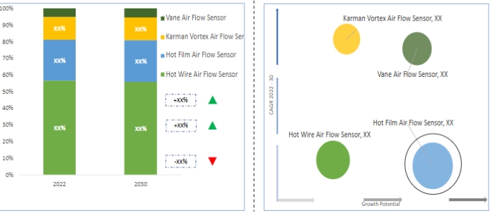
Current mainstream industry research institutions generally indicate that growth momentum in the automotive Mass Air Flow (MAF) sensor market will primarily shift toward thermal film MAF and Manifold Absolute Pressure (MAP) sensors. This trend is highly tied to the proliferation of hybrid vehicles, the penetration of electronically controlled turbocharging technology, and the widespread adoption of digital throttle valves.
Hybrid vehicles' multi-condition intake control demands stringent sensor response accuracy and dynamic adaptability. Hot-film MAF sensors, with their strong interference resistance and wide measurement range, better accommodate airflow fluctuations during fuel-electric transitions. Meanwhile, the high-frequency pressure variations in electronically controlled boost systems, combined with MAP sensors' integrated detection capabilities, enable more precise air-fuel ratio regulation. The electronic control logic of digital throttles also synergizes with the digital signal outputs of these two sensor types, further driving their penetration in mainstream passenger vehicles.
However, traditional Karman vortex sensors will not completely exit the market. Instead, they will gradually transition into "specialized technologies" for niche applications—characterized by "high performance, low versatility."The structural characteristics of these sensors grant them irreplaceable advantages in scenarios involving high airflow throughput, severe oil contamination, and extreme durability requirements: For instance, in heavy-duty commercial vehicles with large-displacement diesel engines, where intake airflow is substantial and highly contaminated with dust and oil, the non-contact detection method of Karman vortex sensors prevents oil residue from affecting measurement accuracy. For equipment like construction machinery and mining vehicles operating long-term in harsh environments, the complex conditions of their intake systems align well with the high mechanical durability of Karman sensors. In extreme temperature and high-vibration scenarios encountered by certain specialty vehicles, Karman sensors also demonstrate superior stability.
Therefore, Karman vortex sensors will persist as a "niche yet essential" solution in specific high-demand automotive and off-road mobile equipment sectors.
Frequently Asked Questions
What is a Karman vortex mass air flow sensor?
A Karman vortex mass air flow sensor is a device that measures the mass flow of air entering an engine based on the Karman vortex street phenomenon. As air flows past the sensor's blunted body (vortex generator), alternating vortices are shed downstream. The sensor detects the frequency of these vortices using optical or ultrasonic elements. A strict linear relationship exists between vortex frequency and air velocity (calculated as f = St·V/d, where St is the Strouhal number). The sensor then outputs a 5 V square wave signal to the ECU. Its core function is to provide the ECU with precise intake air volume data to optimize fuel injection and maintain an ideal air-fuel ratio.
Which vehicles feature a Karman Vortex air flow sensor?
This sensor is primarily used in Japanese high-performance, luxury, and off-road vehicles. Typical models and their original equipment part numbers are as follows:
• Toyota:
Supra A70 (Engine 7M-GTE, OEM Part No.: 89420-30010)
Crown S133 (Engine 1JZ-GTE)
Land Cruiser 80 Series (Engine 1 HZ, OEM Part No.: 89420-60020)
• Lexus:
LS400 UCF10 (Engine 1UZ-FE, OEM Part No.: 89420-50010)
GS300 S141 (Engine 2JZ-GE)
•Mitsubishi:
Lancer EVO III-V (Engine 4G63T, OEM Part No.: MD336199)
Pajero V31/V33 (Engine 6G72)
What is the disadvantage of a Karman vortex sensor?
The primary disadvantages of the Karman vortex sensor stem from its operating principle and intricate internal structure, including:
• Cannot be cleaned arbitrarily: Chemical cleaners (such as flow meter-specific cleaners or isopropyl alcohol) corrode the metal mirror surface and photosensitive components, causing irreversible damage.
• Frequency drift: Long-term exposure to airflow may deform the vortex generator, while aging optical or ultrasonic components disrupts the frequency-to-flow correlation.
• Poor response at low temperatures/low flow rates: During idle or cold start phases, irregular vortex formation can cause signal instability and engine vibration.
• Susceptibility to connector corrosion: Moisture or oil contamination on connector pins can cause signal interruption or distortion, triggering fault codes.
Note: Avoid indiscriminate cleaning and regularly inspect connectors for corrosion to reduce failure risk. Replace the sensor promptly if frequency drift or component damage is detected.
Can you clean a Karman Vortex air flow sensor?
Cleaning is generally not recommended. The sensor's internal metal reflector (coated with a thin aluminum layer) and phototransistor are highly sensitive to chemical solvents and physical contact. As stated on Reddit's automotive forum: "There is no reliable cleaning method... any attempt may render it unusable." Improper cleaning (e.g., spraying MAF-specific cleaner) can easily cause mirror fogging, pin corrosion, or signal failure.
Recommended procedure:
• If only surface dust is present, gently blow compressed air (≤0.2MPa) from the intake to the exhaust port (avoid reverse blowing). If malfunctions like frequency distortion or no signal occur, replace the sensor immediately:
• Disconnect the battery negative terminal and leave disconnected for 3 minutes;
• Select a replacement model matching the original pin count, frequency range, and compensation functionality;
• After installation, start the engine and idle for 5 minutes to complete ECU adaptive learning.