How to Build a Sound Reactive LED Strip that Dances to Music
In the field of embedded development, controlling LED flashing is arguably the most classic introductory experiment.I believe that every enthusiast of MCU is already very familiar with this experiment. Today, this fundamental technology has evolved into more diverse applications, such as sound reactive LED light strips, which can convert music rhythms into vibrant light effects in real-time, instantly bringing your embedded projects to life.
In this project, to keep things simple and help new users get started easily, we have retained only the most basic configuration: a constant-on power indicator LED, plus a programmable status indicator LED. Although the configuration is simple, with clever program design, this little light can do quite a lot. Now, follow the steps and try to realize the interesting phenomenon behind this simple LED!
1.Components & Cost Breakdown


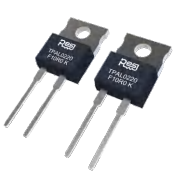
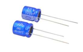


The total cost is approximately $16.5671, and most of the parts are common materials in the field of embedded development that can be reused. Beginners can stock these parts as common tools in their toolboxes. Once you have all the components ready, go ahead and give it a try!
2.Sound reactive LED strip design concept
For beginners in embedded development, LED control is the most fundamental introductory experiment.It is the go-to practical project for nearly all MCU developers. It serves as the foundation for stunning LED matrix designs such as the ‘MSG Sphere’ and ‘Burj Khalifa’,which demonstrate exceptional creativity built upon the fundamentals of LED control. However, considering the practical development efficiency (after all, soldering a large number of LEDs into a light strip requires significant time investment), we will explore more efficient I/O port application scheme today.
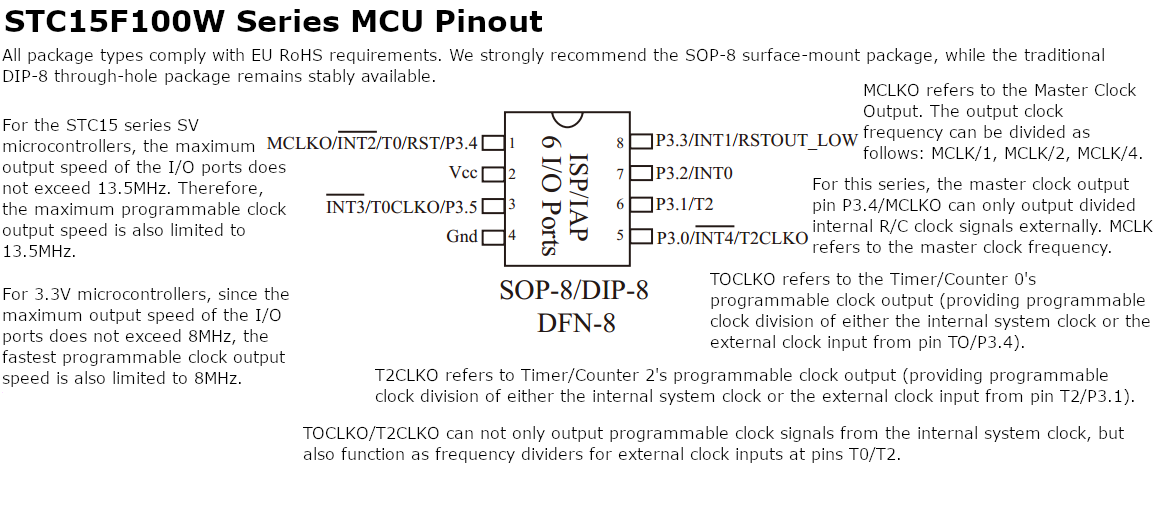
Regarding the allocation strategy for GPIO, we have developed a systematic plan: the basic configuration must include led driver ports, but controlling a single LED lacks technical depth. To maximize resource utilization, we have introduced a passive buzzer module. With this component added, a new concept naturally emerged: why not build a system with audio playback functionality? At this point, the prototype design began to take shape,combining a buzzer with audio output and an LED for visual indication.

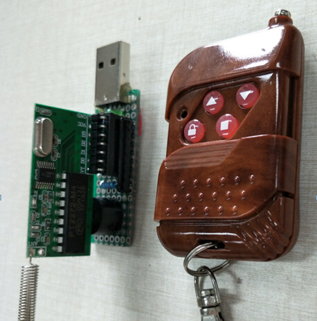
In terms of functional expansion, we adhere to the design concept of ‘sound and light synchronization’: since the buzzer is responsible for ‘singing’, the LED should naturally be responsible for the visual presentation of ‘dancing’. For the remaining four GPIO interfaces, we can use a RF Transceiver Module (the receiver happens to use the M4 interface specification, and the four buttons on the remote control perfectly match the remaining I/O resources).

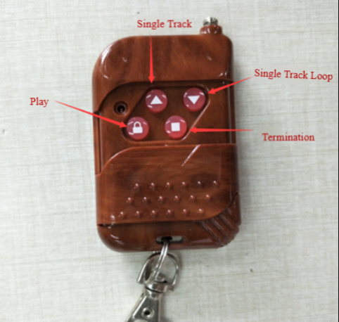
The final interactive logic design is as follows: four control modes are achieved through four buttons on the remote control—play (PLAY), termination(TERMINATION), single track (SINGLE TRACK), and single track loop (SINGLE TRACK LOOP). This design not only achieves 100% utilization of hardware resources but also gives basic components an unexpected, intelligent, interactive experience, greatly enhancing the confidence of beginners.
3. Production Process & Schematic Diagram Sharing
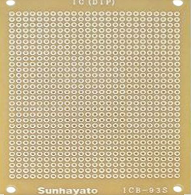
Once the product prototype concept is complete, you can start making it. First, you need to draw the schematic diagram. With the help of professional EDA tools, a complete circuit schematic diagram can be roughly formed in about ten minutes.

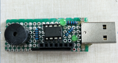
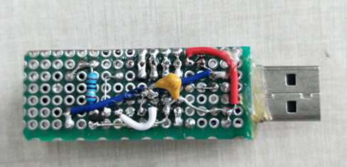
Next, we moved on to the PCB soldering stage. After more than an hour of meticulous work, we finally completed the soldering of the circuit board. Although there is still room for improvement in terms of craftsmanship and aesthetics, the important thing is that it fully meets the functional requirements. The final product measures 63mm × 20mm, which is only about the size of a standard USB flash drive, achieving an extremely compact design.
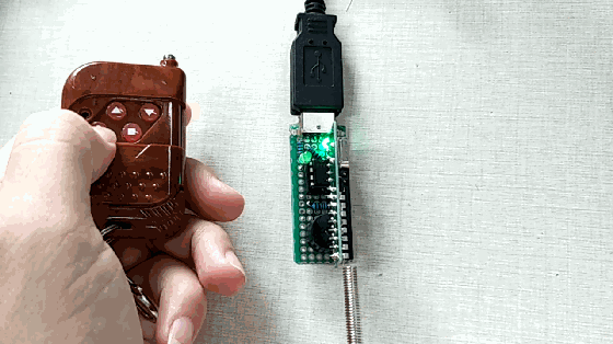
4. Effect display


Recommend Reading: