
Zero-Ohm Resistor: A Comprehensive Guide to Definition, Applications, and Design Techniques
1. What is Zero-Ohm Resistor?
In the microscopic world of electronics, there is an unassuming yet crucial component that directly impacts circuit performance and functionality: the resistor. As one of the most fundamental passive components in a circuit, resistors perform critical functions such as current limiting, voltage division, and impedance matching. However, with the advancement of the electronics industry, the limitations of conventional resistors have become increasingly apparent in specific applications, such as high-frequency wiring or circuits requiring flexible tuning. In response, the Zero-Ohm Resistor was developed.

The Zero-Ohm Resistor, also known as a 0 ohm Resistor or jumper resistor, retains the appearance and manufacturing characteristics of a resistor, achieving the function of connecting conductors through its extremely low resistance value, embodying the ingenuity and innovation of countless engineers. Despite the 'zero' in its name, it is not zero ohm. Instead, its resistance value is extremely close to zero compared to conventional resistors.
Like the ideal pursuit of superconductors, the Zero-Ohm Resistor strives to achieve nearly perfect conductivity in circuits. There are two primary forms of Zero-Ohm resistors: axial lead-type and surface-mount type. The former features metal leads extending from both sides, suitable for through-hole soldering. At the same time, the latter can be directly mounted on the PCB surface, adapting to modern high-density integration.
Additionally, many manufacturers offer various precision grades for these resistors, such as F-class (error ≤ 10 milliohms), G-class (error ≤ 20 milliohms), and J-class (error ≤ 50 milliohms), ensuring their stability and reliability in practical applications.
2. Main Functions and Applications of Zero-Ohm Resistors
A Zero-Ohm Resistor is a resistor with a resistance value of Zero-Ohms, commonly used in PCB design and other applications, making it an ideal resistor. What are the specific applications of Zero-Ohm Resistors?
2.1. Convenient Debugging or Compatibility Design
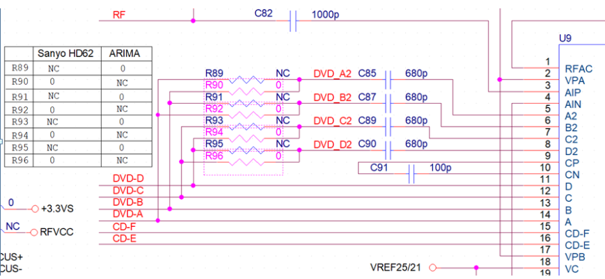
When hardware engineers design PCB boards, they must consider compatibility issues as much as possible. For example, a chip pin may have two functions: driving a buzzer or driving an LED, but these two functions cannot operate simultaneously.
To allow users to freely choose which module to drive on the same circuit board, Zero-Ohm Resistors are added to the lines connecting the buzzer and LED. If the buzzer needs to be driven, the Zero-Ohm Resistor on the buzzer's circuit path is soldered; if the LED needs to be driven, the resistor on the LED's circuit path is soldered.
As shown in the figure below, you can choose which signal to use by soldering the corresponding resistor. When configuring the system, especially for embedded PCB boards, the startup signal selection is determined by the board's configuration, which requires the use of a Zero-Ohm Resistor.
2.2. Used as a jumper wire with optimized high-frequency performance
Compared to conventional wires, Zero-Ohm Resistors offer more stable parasitic effects while providing a uniform current path through their flat surface structure and metal film material. This helps mitigate the skin effect (where high-frequency currents concentrate on the surface of the conductor, causing the equivalent resistance of conventional wires to rise sharply with frequency), thereby improving impedance matching in high-frequency circuits (e.g., RF module layout).
2.3. Jumping wires to simplify routing
During the PCB layout and routing phase, you may encounter situations where routing is not feasible, especially when the circuit board area is small and there are many connections. In such cases, a Zero-Ohm Resistor can be connected to bypass the preceding wires.
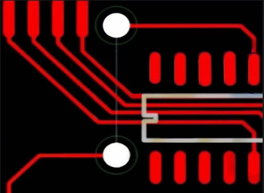
For example, these two white solder points would require a lengthy route to connect directly. On a single-layer PCB, drilling holes from below is not feasible. By using a Zero-Ohm Resistor to connect them, the cost of purchasing multi-layer PCBs can be reduced.
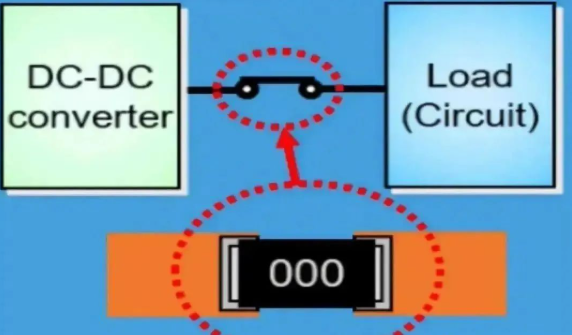
2.4. When matching circuit parameters are uncertain, use a Zero-Ohm Resistor as a substitute
When matching circuit parameters and the values are uncertain, during actual testing, it may be necessary to remove a resistor or replace it with one of a different value to obtain the optimal solution. In such cases, a Zero-Ohm Resistor is typically used. Replace the resistor with a Zero-Ohm Resistor, and after actual testing and parameter confirmation, replace it with a component of the specific value.
For example, there are two different power supply options, 5V and 10V, but it is unclear whether different power supply voltages will have an unknown impact on the entire circuit. In such cases, a Zero-Ohm Resistor is typically used to connect the two options. During circuit testing, the appropriate power supply is selected and connected to the circuit.
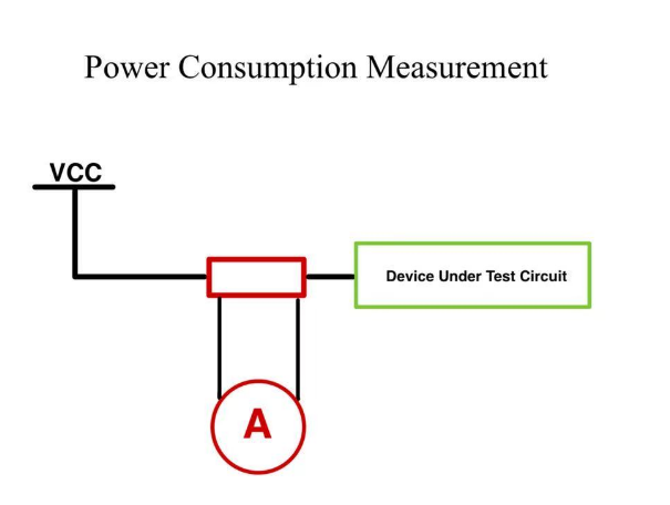
2.5. Measuring Circuit Power Consumption
When the power consumption of a specific chip or an entire circuit is uncertain, connect a Zero-Ohm Resistor in series at the power supply end. After the PCB board is prototyped, remove it and use a multimeter to measure the current directly between the two solder points. This will provide the actual operating current, enabling calculation of the total power consumption of the chip or the entire circuit.
To measure the current consumption of a specific part of the circuit, connect a Zero-Ohm Resistor and a current meter. This makes it easier to measure current and is suitable for measuring high currents.
As shown in the figure below, connect a Zero-Ohm Resistor between the power supply and the circuit under test.
2.6. Acting as a capacitor or inductor
At high frequencies, a Zero-Ohm Resistor can act as a small capacitor or inductor when its characteristics match those of the external circuit, effectively resolving EMC issues such as ground-to-ground or power supply-to-chip pin connections.
2.7. As a fuse for overcurrent protection
Due to the high current-carrying capacity of PCB traces, short circuits or overcurrents may occur without melting, potentially causing more severe accidents. However, Zero-Ohm Resistors have a low current-carrying capacity and will melt first during overcurrent conditions, thereby disconnecting the circuit and preventing more severe accidents.
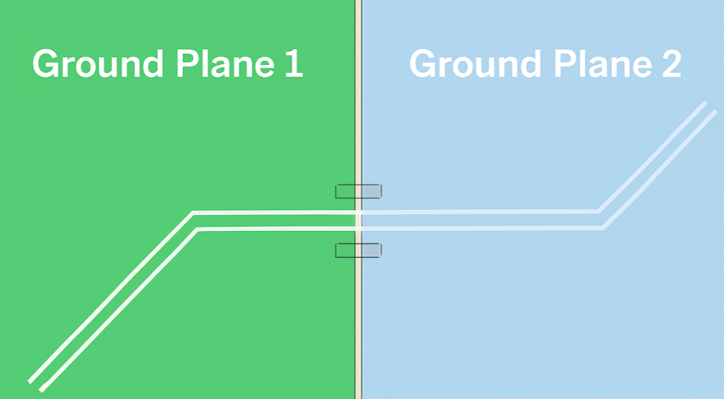
2.8. Single-point grounding for analog and digital grounds
In circuit design, especially in mixed circuits such as digital and analog circuits, it is often necessary to separate and connect the two grounds at a single point.
We can use a Zero-Ohm Resistor to connect these two grounds instead of connecting them directly. This divides the ground line into two networks, which is more convenient when handling large areas of copper plating, preventing 'floating ground' and the accumulation of charges, which can cause static electricity.
For more details, please refer to the figure below. When configuring, especially for embedded boards, the startup signal is selected through the board configuration, allowing the startup source to be specified. At this point, a Zero-Ohm Resistor is required.

2.9. Used for current loops during cross-connection
After splitting the electrical ground plane, the shortest return path for signals is interrupted. As a result, the signal loop must take a detour, forming a large loop area, which enhances the influence of electric and magnetic fields, thereby increasing the likelihood of interference.
By installing a Zero-Ohm Resistor across the split area, a shorter return path can be provided, thereby reducing interference.
2.10. Circuit Configuration
Jumpers and dip switches are generally not found on standard products. However, users may accidentally alter settings, leading to unintended consequences and misunderstandings. To reduce maintenance costs, Zero-Ohm Resistors can be used to replace jumpers and other components, which are soldered directly onto the board.
2.11. Noise Suppression
Due to the inherent characteristics of Zero-Ohm Resistors, they effectively suppress loop currents, thereby reducing noise. In reality, Zero-Ohm Resistors are not truly impedance-free; only superconductors can achieve actual zero impedance. Therefore, Zero-Ohm Resistors act as attenuators across all frequency bands.
3. Design and manufacturing advantages of zero-ohm resistors
Although a Zero-Ohm Resistor is electrically equivalent to a wire, it offers unique advantages in electronic circuit design and manufacturing, making it more popular than using wires or jumpers directly in many applications.
3.1.Compatible with SMT equipment, significantly improving production efficiency
Firstly, Zero-Ohm Resistors utilize standard resistor packaging (such as 0201, 0402, 0603, 0805, 1206, etc.), allowing them to be fully integrated into existing surface-mount technology (SMT) production lines for automated placement.
SMT placement machines can mount Zero-Ohm Resistors at high speeds and with precision, similar to standard resistors, significantly improving production efficiency, reducing labor costs, and minimizing errors. This provides circuit designers with exceptional flexibility and convenience.
In contrast, manual soldering of jumper wires is inefficient, inconsistent, and prone to errors.
3.2.Replacing traditional jumper wires to avoid interference
Cross-connecting traces is the core advantage of zero-ohm resistors. When complex routing on single-layer or multi-layer boards prevents two conductive paths that need to be connected from being directly connected on the same layer, a Zero-Ohm Resistor can be placed on the PCB (like a regular component) to connect them by spanning different layers or bypassing obstacles. This dramatically simplifies PCB routing complexity, increases routing density, and improves routing success rates.
3.3. Easy to modify, beneficial for production and quality control
The core value of Zero-Ohm Resistors lies in their seamless integration into SMT and the flexibility and convenience they provide for circuit design.
Essentially, it functions as a 'programmable conductor' or 'configurable connection point'. Its design and manufacturing advantages are primarily reflected in significantly reduced manufacturing costs, greatly improved production efficiency and quality consistency, enhanced flexibility and adaptability of PCB design, ease of implementing configuration options, testing, and post-production modifications.
Although the material cost of a single Zero-Ohm Resistor may be slightly higher than that of a short segment of wire, the substantial improvements in overall production efficiency and design flexibility it offers make it indispensable in mass production. It serves as a clever tool for electronic engineers to strike a balance between complex PCB design and efficient manufacturing.
4. Electrical characteristics and parameters of Zero-Ohm Resistors
4.1. The value of a Zero-Ohm Resistor
For the resistance value of a Zero-Ohm Resistor, we can find the answer in the EN 60115-2-2015 resistance standard document. The ideal resistance value of a Zero-Ohm Resistor is zero ohms, but due to production process precision and other issues, there will be some errors.
The maximum resistance error for a Zero-Ohm Resistor has three options: 10 milliohms, 20 milliohms, and 50 milliohms. According to the document description, the error in a Zero-Ohm Resistor is permissible.
Zero-Ohm Resistors can have various tolerances, which primarily depend on the type manufactured by the resistor manufacturer.
For example, the specification sheets for Zero-Ohm Resistors from Rohm and YAGEO indicate that the maximum tolerance for the resistance value of Zero-Ohm Resistors is 50 milliohms. Therefore, the maximum resistance value of commonly used Zero-Ohm Resistors generally does not exceed 50 milliohms.
4.2.Current-carrying capacity of Zero-Ohm Resistors
The current-carrying capacity of a Zero-Ohm Resistor primarily depends on its physical packaging size (which determines the rated power), the actual small resistance value (typically in the milliohm range), and the ambient temperature during operation (the power derating curve of the resistor changes). These factors result in different current-carrying capacities among Zero-Ohm Resistors from other manufacturers.
4.3.Lifespan and aging mechanism
The lifespan of a Zero-Ohm Resistor directly affects the long-term stability of the circuit. Its aging mechanisms can be broadly categorized into steady-state current aging and pulse current tolerance.
When a Zero-Ohm Resistor operates continuously at 80% of its rated current, the resistance drift can be controlled within 1% per year; however, overloading can directly cause thermal degradation of the resistive element.
According to the Arrhenius model, when the temperature exceeds 100°C, each additional 10°C increase halves the lifespan of the resistive element. This is known as steady-state current aging of a Zero-Ohm Resistor.
Pulse current tolerance refers to the ability to withstand short-term pulses (e.g., 1 ms) reaching 5–10 times the rated current. However, repeated pulses can cause cumulative damage, thereby affecting the lifespan of Zero-Ohm Resistors and accelerating aging.
In addition to these scenarios, specific special application environments can also lead to reduced resistor lifespan, such as localized temperature increases caused by high-frequency circuits or the use of the resistor as a fuse element.
5. Zero-Ohm Resistor Adjustment and Testing Techniques
5.1. Rated Current and Package Selection
The current capacity of a Zero-Ohm Resistor is determined by its package size. For example, the 0402 package typically has a current rating of 1A (e.g., RC0402JR-070RL), the 0603 package is 1.5A (e.g., ERJ-3GEY0R00V), and the 0805 package is 2A (e.g., CRCW08050000Z0EA). When designing, the actual current must be calculated, and a margin should be left (e.g., using a 70% derating factor) to extend the service life and ensure circuit stability.
Due to current-carrying capacity limitations caused by package size constraints, Zero-Ohm Resistors cannot completely replace the physical properties of wires in certain exceptional cases. For example, under high current conditions, the resistive element may overheat and cause the film layer to melt, while the wire only experiences a temporary temperature rise during this process.
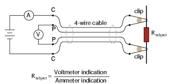
5.2. Measurement Methods and Factors Affecting Actual Resistance
The most precise method for measuring the actual resistance of a Zero-Ohm resistor is the four-wire Kelvin measurement method, which involves separating the current application and voltage detection paths to eliminate the influence of test cable resistance.
Although the nominal resistance value of a Zero-Ohm resistor is 0Ω, there is an actual deviation in the order of milliohms (e.g.±50mΩ). In high-current scenarios, this resistance value can cause significant voltage drops (e.g., a 2A current flowing through a 50mΩ resistor results in a 0.1V voltage drop), which can affect the accuracy of low-voltage circuits.
5.3. High-Frequency Parasitic Parameters
Zero-Ohm resistors have parasitic inductance (approximately several nH) and capacitance (approximately 0.1 pF). In high-frequency applications (such as RF or high-speed digital circuits), these may introduce signal reflection or resonance, necessitating the evaluation or selection of high-frequency-specific models (such as thin-film process resistors).
5.4. Thermal Management and Soldering Process
Resistors may overheat during high current flow, potentially causing solder joints to melt or the PCB to burn out. Ensure proper heat dissipation design (e.g., avoid dense placement in enclosed spaces). When manually soldering, control the temperature (typically with a peak temperature of ≤ 260°C) to prevent resistor cracking or PCB bubbling.
5.5. Trade-offs Between Alternative Solutions
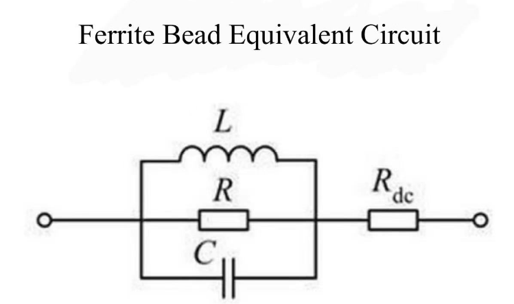
Ferrite beads vs. inductors: When filtering is required, ferrite beads can suppress high-frequency noise but have higher DC resistance (e.g., 100 mΩ or higher); Zero-Ohm Resistors are suitable for pure DC paths.
Fuses: For reliable overcurrent protection, fuses with well-defined melting characteristics should be selected instead of relying on Zero-Ohm Resistors.
5.6. Standards and Certification Requirements
In safety certifications (e.g., UL, IEC), Zero-Ohm Resistors may not be recognized as fuses and should be selected based on their actual functionality.
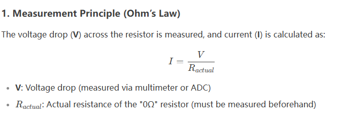
5.7. Using Zero-Ohm Resistors for Current Measurement
Since Zero-Ohm Resistors have milliohm-level resistance values, a small voltage drop occurs when current flows through them. By accurately measuring this voltage drop, the current can be calculated.
6. Future Trends and Innovations in Zero-Ohm Resistors
Zero-Ohm resistors, though seemingly simple electronic components, are not stagnating in their development. Instead, they are continuously evolving to meet the increasingly stringent performance requirements and miniaturization trends in electronic devices.
6.1 Core Development Trends focus on enhanced current-carrying capacity, size reduction, reliability improvement, and functional innovation
(1) Development of Higher-Performance Products
With the widespread adoption of fast charging, high-performance computing, high-power lighting, and motor drives, the demand for circuit current has surged, driving the need for Zero-Ohm Resistors toward higher current-carrying capacity.
This requires material innovations, such as the use of advanced alloys with lower resistivity, and optimized electrode structures and heat dissipation designs (e.g., enhanced pads or improved substrates), aiming to achieve stable current flow of 5A, 10A, or even higher in miniature packages such as 0402 or 0201.
Meanwhile, impedance at the milliohm level plays a critical role in precision circuits, driving manufacturing processes toward higher precision. This is achieved through material purity control, structural uniformity optimization, and rigorous screening to reduce actual impedance and enhance batch consistency continuously.
(2) Material Revolution in High-Density Integration
Miniaturization is another clear trend, with 01005 and smaller package sizes becoming inevitable. At the same time, mechanical strength and soldering reliability must be ensured even in miniature sizes. Array packaging has also emerged to meet the demands of high-density PCB layouts.
In harsh environments such as those found in automotive electronics and industrial control, reliability requirements have reached unprecedented levels. This has driven upgrades in terminal electrode materials (such as thick silver or corrosion-resistant alloys), internal structure optimization to enhance thermal fatigue resistance, and improvements in protective coatings to ensure stable operation under high temperatures, humidity, and vibration/shock conditions.
6.2. Innovation primarily manifests in functional integration and material breakthroughs
(1) Disruptive expansion of functional roles
On one hand, Zero-Ohm Resistors transcend their role as mere 'jumpers', exploring deep integration with fuse functions to develop 'fuse resistors' with precise, fast, and reliable fuse characteristics, or integrating specialized structures for easy test probe contact.
(2) Pushing the Limits of Materials Science
On the other hand, materials science is the key to breakthroughs. New low-resistance alloys, high-thermal-conductivity substrates (such as aluminum nitride), and even the exploration of nanomaterials like carbon nanotubes and graphene (though cost challenges remain significant) aim to achieve ultra-low impedance and exceptional heat dissipation.
(3) Intelligence and Enhancing Component Value
Intelligent elements, such as miniature RFID traceability coding, may also find applications in high-end fields.
In the future, Zero-Ohm Resistors will focus more on their unique value-added areas—such as high-reliability single-point grounding, convenient debugging and rework points, and low-cost fuse protection—competing with advanced PCB technology and specialized miniature fuses. By continuously improving materials, structures, and processes, they will solidify their position as the 'small yet critical' bridge in electronic systems.
Recommended Reading:
What is GND in Electronic Circuit?
Understanding DC Motor Components: A Comprehensive Guide
In-Depth Analysis of Monostable Multivibrators
Inductor Color Code Guide: How to Read and Decode Inductor Color Bands Accurately


