Arduino Hands-on - Water Flow Sensor Module
Experiment: Hall Effect Water Flow Sensor Module for Coffee Machine and Direct Drinking Machine Flow Monitoring.
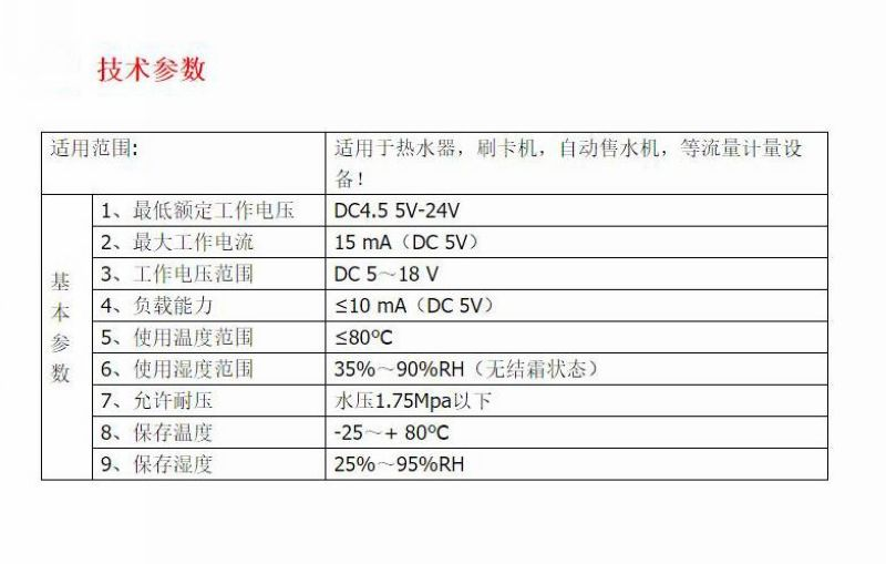
A water flow sensoris an instrument that senses the flow rate of water and outputs pulse signals or current, voltage, and other signals accordingly. The output signal is in a certain linear proportion to the water flow rate, with corresponding conversion formulas and comparison curves. Therefore, it can be used for water control management and flow calculation. In terms of thermal energy, when combined with a transducer, it can measure the loss of energy of a medium over a period of time, such as in heat meters. Water flow sensors are mainly used in conjunction with control chips, microcontrollers, and even PLCs. They have the functions of accurate flow control, setting cyclic action flow rates, water flow display, and cumulative flow calculation.
Flow rate
refers to the amount of fluid passing through a closed pipeline or open channel per unit time, also known as instantaneous flow rate. When the amount of fluid is expressed in terms of volume, it is called volume flow rate; when it is expressed in terms of mass, it is called mass flow rate. The volume of fluid passing through a certain section of a pipe in unit time is called the volume flow rate at that cross-section. Simply referred to as flow rate, represented by Q. The measurement of fluid flow within a certain channel is collectively referred to as flow measurement. The fluids measured in flow rate determination are diverse, including gases, liquids, and mixtures; with variations in temperature, pressure, and flow rates, the required measurement accuracy varies accordingly. Therefore, the task of flow rate measurement is to study various corresponding measurement methods based on the measurement purpose, type of fluid being measured, flow conditions, measurement location, etc., and ensure the correct transmission of flow rate values. For example, river flow rate refers to the cubic meters of water flowing past a point in the river in one second. Generally speaking, the further downstream, the greater the flow rate. Therefore, when identifying the direction of rivers on maps, it is generally from narrow to wide. River flow rate refers to the amount of water passing through a cross-section of the river in a unit time, usually expressed in cubic meters per second. Flow rate can also be expressed as the total amount of water flowing out in a month, season, or year. From a hydrodynamics perspective, flow rate should be defined as the volume of water passing through a certain cross-sectional area in unit time, commonly measured in cubic meters per second, often used for measuring the inflow and outflow of river and lake sections. In terms of measurement methods, from a hydrometric station perspective, they can be categorized into buoy method, current meter method, ultrasonic method, etc., with the current meter method offering the highest measurement accuracy.

Principle of Water Flow Sensor 1
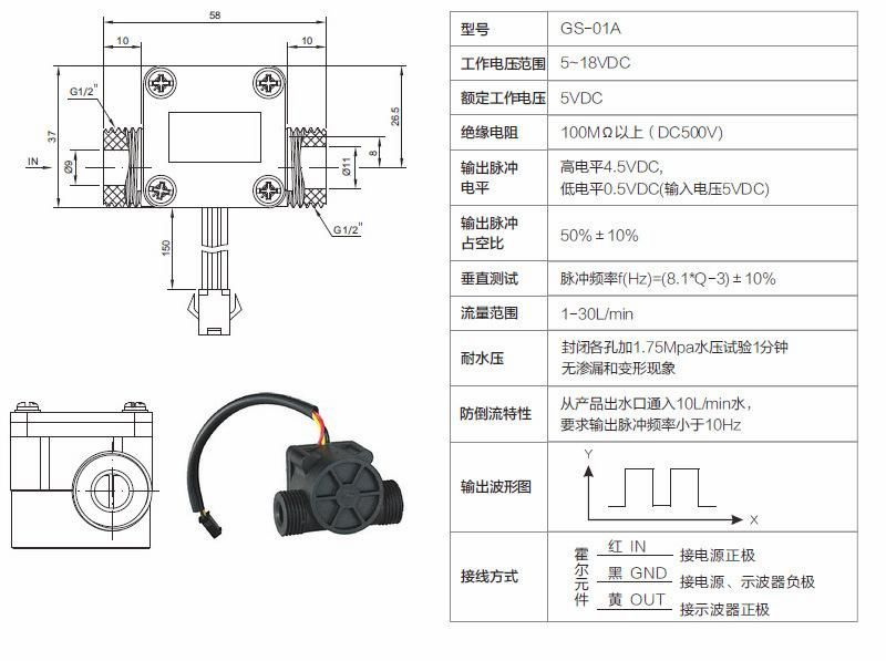
The water flow sensor utilizes the Hall effect of the Hall element to measure the magnetic physical quantity. A negative load resistor is connected in series with the positive pole of the Hall element, and a 5V direct current voltage is applied while the current direction is orthogonal to the magnetic field direction. When water flows through the turbine switch housing to drive the magnetic rotor rotation, a rotating magnetic field with different magnetic poles is generated, cutting the magnetic induction lines and producing high and low pulse levels. The output pulse signal frequency of the Hall element is directly proportional to the speed of the magnetic rotor, which is also proportional to the flow rate of water. Based on the magnitude of the water flow, the gas water heater is activated. The empirical formula for the pulse signal frequency is shown in Equation (1):
f = 8.1q - 3 (1)
Where:
f - Pulse signal frequency, Hz
q - Water flow rate, L/min
The feedback signal from the water flow sensor is used by the controller to determine the value of the water flow rate. Depending on the model of the gas water heater, selecting the optimal starting flow rate can achieve startup even under ultra-low pressure conditions (below 0.02 MPa).
Working Principle of Water Flow Sensor 2
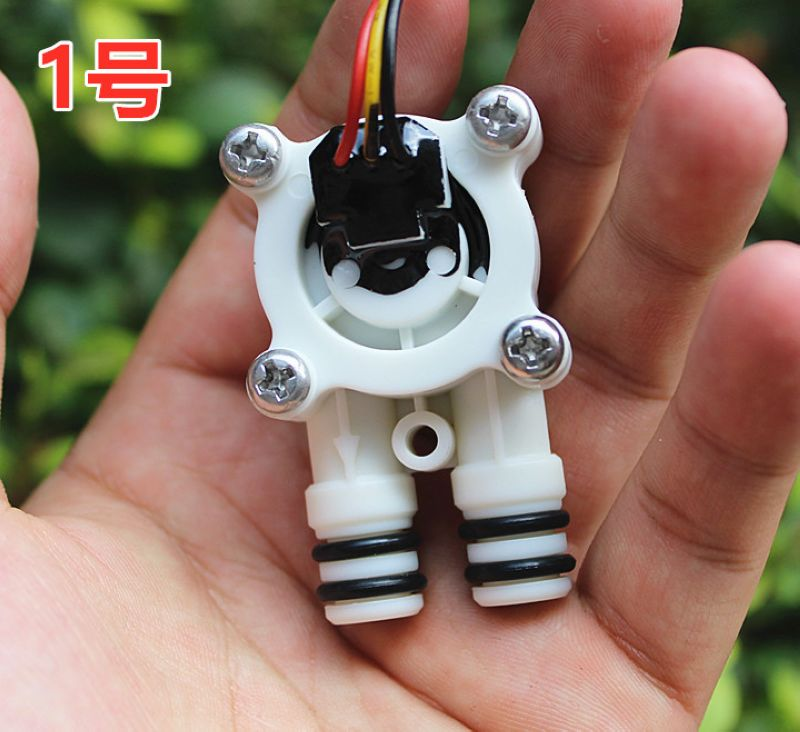
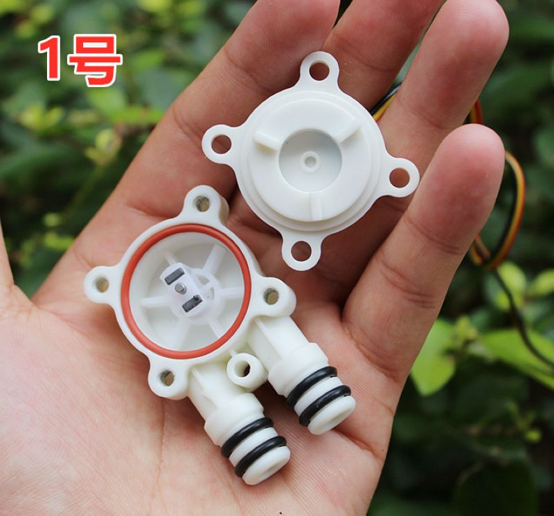
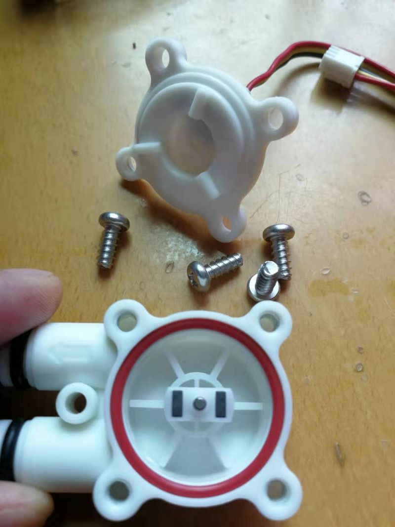
The water flow sensor is mainly composed of a copper valve body, a water flow rotor assembly, a steady flow component, and a Hall element. It is installed at the inlet of the water heater to measure the incoming water flow. When water flows through the rotor assembly, the magnetic rotor rotates, and the speed varies linearly with the flow rate. The Hall element outputs corresponding pulse signals back to the controller, which then determines the size of the water flow, adjusts the current of the proportional valve through the controller, thereby controlling the gas volume through the proportional valve to prevent the phenomenon of feeling cold in winter and warm in summer during the use of the gas water heater.
The water flow sensor fundamentally solves the disadvantages of high water pressure required for the start-up of differential pressure-type water and gas linkage valves and the easy misoperation of flap-type water valves causing dry burning. It has advantages such as sensitive response, long service life, fast action, safety and reliability, convenient connection, and the ability to start with extremely low flow rates (1.5L/min), making it highly favored by users.
The water flow rotor assembly is mainly composed of a turbine switch shell, a magnetic rotor, and a braking ring. When using the water flow switch method, its performance is superior to that of mechanical differential pressure plate structures, and the size is significantly reduced. When water flows through the turbine switch shell, it drives the magnetic rotor to rotate. When different magnetic poles approach the Hall element, the Hall element conducts; when they move away, the Hall element disconnects. Thus, the rotor speed can be measured. Based on the measured water flow rate, rotor speed, and output signal curve (voltage), the start-up water pressure of the water heater and the corresponding start-up water flow rate and rotor start-up speed can be determined. Through the control circuit, the water heater can start working when the rotor speed is greater than the start-up speed; it stops working when the speed is below that threshold. Generally, the start-up water pressure of the water heater is set at 0.01MPa, and the start-up water flow rate is between 3-5L/min (meeting the maximum temperature rise limit of the water heater standard). Additionally, due to the cutting of water in the permanent magnetic material magnetic field, the water becomes magnetized water, increasing the oxygen content in the water, giving a refreshing feeling after bathing. The role of the braking ring is to stop the rapid rotation of the magnetic rotor when water is shut off, terminating the output of pulse signals. If the controller does not receive pulse signals, it immediately controls the gas proportional valve to close, cutting off the gas source to prevent dry burning.
The function of water flow sensor
Water flow sensors with switch signal output and pulse signal output, which can be connected to water and electricity simultaneously to prevent dry heating. These sensors are produced by Saimor.
The linear proportional pulse signal output is proportional to the flow rate, enabling adjustment of heating power to achieve a constant temperature effect. This method is widely used in most constant-temperature heaters and gas water heaters. Nowadays, some electric faucets and hand washers also adopt water flow sensors.
Water flow sensors fundamentally solve the problems of high water pressure when starting a differential pressure water-gas linkage valve and the risk of dry heating due to the sensitive action of a flip-type water valve. They have advantages such as sensitive response, long lifespan, quick action, safety and reliability, convenient connection, and the ability to start at ultra-low flow rates (1.5L/min), making them highly favored by a large number of users.
Precautions for using water flow sensors.
When magnetic materials or objects generating magnetic forces approach the sensor, its characteristics may change.
To prevent particles and debris from entering the sensor, it is necessary to install a filter screen at the inlet of the sensor.
The installation of water flow sensors should avoid environments with strong vibrations and shaking to maintain measurement accuracy and precision of the sensor.
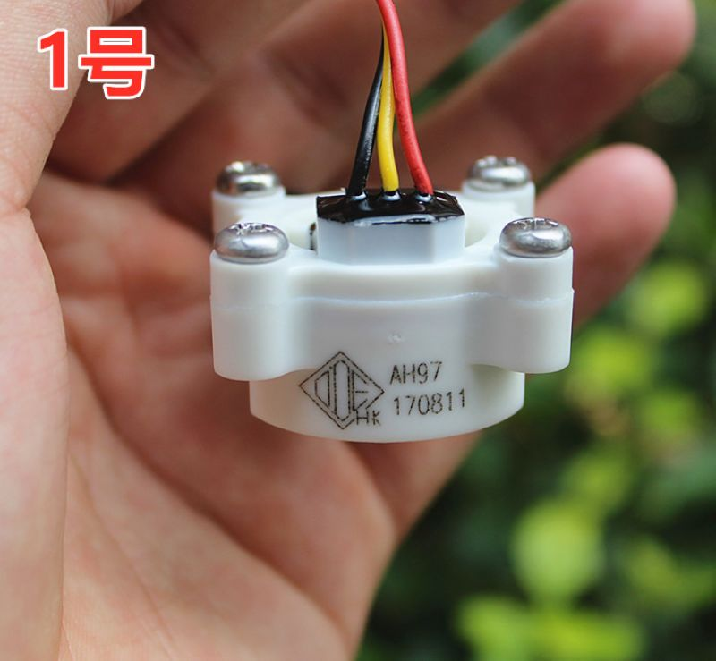
Wiring method:
Red wire IN connects to the positive pole.
Yellow wire OUT is the signal output wire.
Black wire GND connects to the negative pole.


The experimental serial port plotter returns the results

Experimental setup illustration
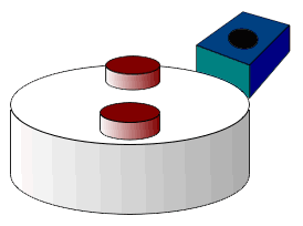
The principle of pulse recording is to set magnetic induction points on the rotating disk, triggering an electrical signal output each time the magnetic field passes through the sensor.
By utilizing an external interrupt function for counting, when the sensor is triggered by a magnet, the program interrupts, executes the counting function, and records one count. By multiplying the number of rotations in every 1000 milliseconds by 30 (due to dual magnets), the real-time speed is calculated.