Arduino Hands-On - TTL to RS-485 Module
Experiment: TTL to RS-485 Module MAX485 RS485 Module

MAX485 is an 8-pin chip that serves as a standard RS485 transceiver, capable of half-duplex communication. It includes an output driver and a signal receiver. MAX485 features a low-power design with a static current of only 300uA. With its tri-state output characteristic, up to 32 MAX485 chips can be connected to the bus simultaneously. The communication baud rate can reach up to 2.5M.

Pin Definitions of MAX485:
● RO (Pin 1): Output pin for received signals. It can output bus signals from A and B pins to the microcontroller. This is a COMS level signal that can be directly connected to a microcontroller.
● RE (Pin 2): Control pin for receiving signals. When this pin is low, the RO pin is active, allowing MAX485 to output signals from the bus to the microcontroller via RO; when this pin is high, the RO pin is in a high-impedance state.
● DE (Pin 3): Control pin for output signals. When this pin is low, the output driver is disabled; when this pin is high, the output driver is enabled, and the output signal from the DI pin is loaded onto the bus via the A and B pins. This is a COMS level signal that can be directly connected to a microcontroller.
● DI (Pin 4): Input pin for the output driver. This is a COMS level signal that can be directly connected to a microcontroller. When DE is high, the signal from this pin is loaded onto the bus via the A and B pins.
● GND (Pin 5): Ground.
● A (Pin 6): Connected to the A end of the RS485 bus.
● B (Pin 7): Connected to the B end of the RS485 bus.
● Vcc (Pin 8): Power supply pin. Power supply should be within the range of 4.25V to 5.75V.

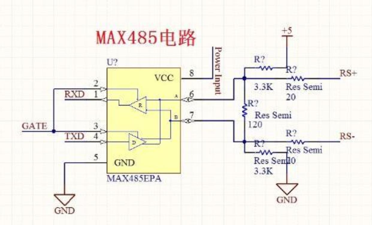
MAX485 operates with a single power supply of +5V, with a rated current of 300μA, and uses half-duplex communication. It performs the function of converting TTL levels to RS-485 levels. The structure and pins of the MAX485 chip are simple, containing an internal driver and receiver. The RO and DI pins serve as the output of the receiver and the input of the driver, respectively. When connecting to a microcontroller, simply connect them to the RXD and TXD pins of the microcontroller. The /RE and DE pins are the enable pins for receive and transmit functions. When /RE is logic low, the device is in receive mode; when DE is logic high, the device is in transmit mode. Since MAX485 operates in half-duplex mode, only one microcontroller pin is needed to control these two pins. The A and B pins are the differential signal terminals for receive and transmit functions. When the level at pin A is higher than B, it represents a transmitted data of 1; when the level at A is lower than B, it represents a transmitted data of 0. The wiring to connect MAX485 to a microcontroller is straightforward—just one signal controls the receive and transmit functions of MAX485. Additionally, a matching resistor can be placed between the A and B terminals, typically a 100Ω resistor.


Several application circuits using MAX485:


TTL to RS-485 Module MAX485 RS485 Module

Module Features:
● Equipped with MAX485 chip, a low-power, slew-rate-limited transceiver for RS-485 communication.
● Comes with onboard 5.08mm pitch 2-pin screw terminals for easy RS-485 communication wiring.
● All chip pins are already accessible and can be controlled and operated by a microcontroller.
● Operating Voltage: 5V
● Board Dimensions: 46mm x 12mm


Module Electrical Schematic
Compared to TTL communication, RS485 offers advantages such as long transmission distances, strong anti-interference capabilities, and the ability to daisy-chain a large number of RS485 devices. Most importantly, it is compatible with a wide range of industrial-grade devices that use various RS485 protocols. For users who require stable long-distance communication between multiple devices, RS485 is an excellent choice.
● Operating Voltage: 5V
● Equipped with MAX485 chip on board
● Low power consumption for RS485 communication
● 5.08mm pitch 2-pin terminals for convenient RS-485 communication wiring
● Board dimensions:44 x 14mm
● Allows for serial communication up to a distance of 1200 meters

PINOUT for MAX-485 TTL to RS-485 Converter Module:
VCC 5V
A Non-inverting receiver input, non-inverting driver output
B Inverting receiver input, inverting driver output
GND Ground (0V)
RO Receiver output (RX pin)
RE Receiver output (active low)
DE Driver output (active high enable)
DI Driver input (TX pin)

RS485 has evolved from RS232 and RS422, addressing the shortcomings of poor interference resistance, limited communication distance, and low data rates. It enhances the multi-point, bidirectional communication capability by allowing multiple transmitters to be connected on the same bus line. Additionally, RS485 increases the drive capacity of transmitters, adds collision protection features, and extends the common-mode range of the bus.
RS485 can be implemented in two ways: using two-wire or four-wire configurations. The two-wire system enables true multi-point bidirectional communication. Its key characteristics include:
● RS485 interface signal levels are lower than RS231-C, reducing the risk of damaging interface circuit chips. Moreover, these levels are compatible with TTL logic, facilitating connections to TTL circuits.
● The maximum data transmission rate for RS485 is 10Mbps. The length of balanced twisted-pair cables is inversely proportional to the transmission rate. At 100Kbps, only then can the specified maximum cable length be utilized, achieving the highest data transfer speed over very short distances.
● RS485 interfaces employ a combination of balanced drivers and differential receivers, providing strong common-mode interference resistance and superior noise immunity. This results in longer communication distances, with a maximum transmission distance of approximately 1200m, but practically reaching up to 3000m.
● RS485 allows up to 128 transceivers to be connected on the bus line, demonstrating multi-station capability. Two termination resistors are required, with their impedance matching the transmission cable's characteristic impedance. Within short distances of 300m, termination resistors may not be necessary.

Experimental Setup Diagram