Arduino Hands-On --- Photoresistor Sensor Module
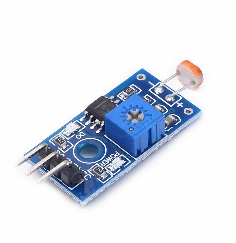
Experiment 2: Photosensitive Resistor Sensor Module
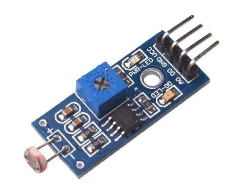
A photoresistor is a specialized resistor made from semiconductor materials such as cadmium sulfide or cadmium selenide. Its working principle is based on the internal photoelectric effect. The stronger the light, the lower its resistance value; as the intensity of illumination increases, the resistance decreases rapidly, with the bright resistance value being reduced to below 1kΩ. Photoresistors are highly sensitive to light; in the absence of light, they exhibit high resistance, typically reaching up to 1.5MΩ in dark conditions. Due to their unique properties, photoresistors are anticipated to see extremely widespread applications as technology continues to advance.
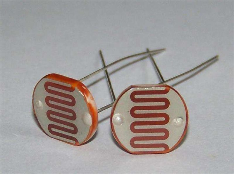
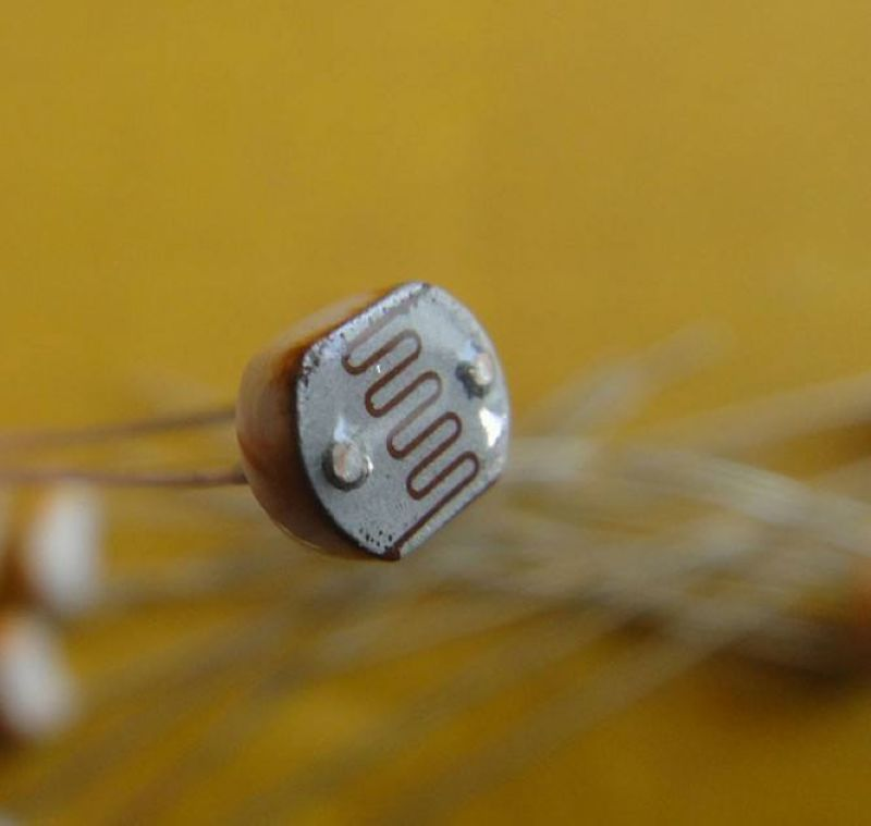
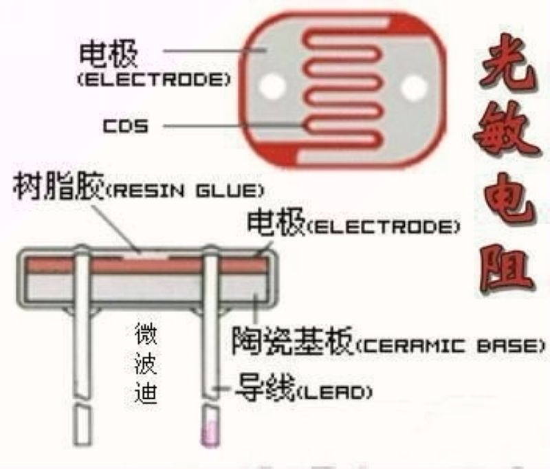
A photoresistor typically comprises a photosensitive layer, a glass substrate (or resin moisture-proof film), and electrodes. In circuit diagrams, a photoresistor is represented by the letters "R," "RL," or "RG."
Primary Applications:
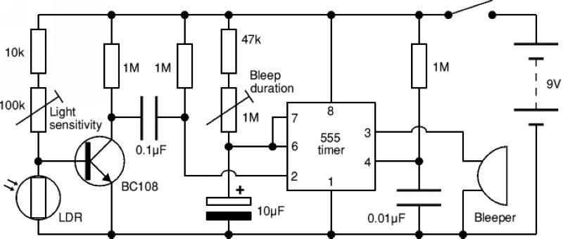
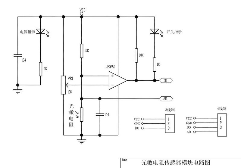
Light intensity detection, light intensity sensors, light-seeking modules for smart cars, etc. Below is a schematic of the conventional application circuit.
Module Parameters:
Operating Voltage: DC 3.3-5V
Photoresistor Model: 5516
Module Pins: 3-pin or 4-pin (the 4-pin version includes an additional analog output pin AO)
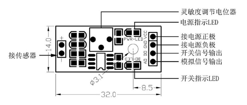
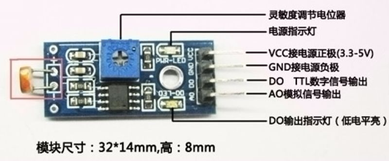
Wiring Diagram for the Module:
VCC - Connect to positive power supply (3.3-5V)
GND - Connect to negative power supply
DO - TTL switch signal output
AO - Analog signal output
Circuit diagram of the photoresistor sensor module
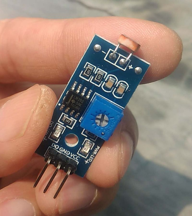
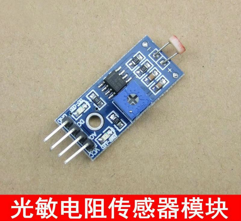
Module Features:
Operating Voltage: 3.3V-5V
Utilizes a Wide-Range Voltage LM393 Comparator
Equipped with Fixed Bolt Holes for Easy Installation
Employs a Sensitive Photocell Sensor
Small PCB Board Dimensions: 3.2cm x 1.4cm
Includes an Adjustable Potentiometer for Tuning Light Detection Sensitivity
Output Formats: DO Digital Switch Output (0 and 1) and AO Analog Voltage Output
Comparator Output: Clean Signal, Good Waveform, Strong Driving Capability, Exceeding 15mA.
Module Experiment Instructions:
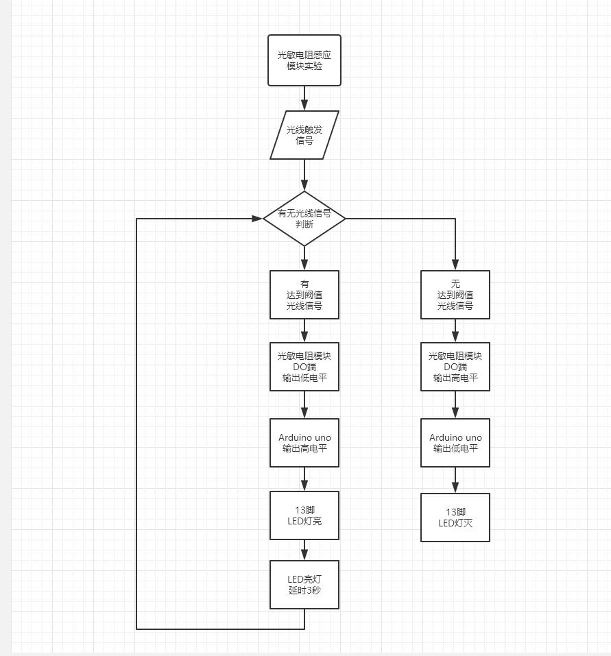
The analog output AO from the small circuit board of the photoresistor module can be connected to an AD module. Through AD conversion, more precise numerical values of the ambient light intensity can be obtained.The LED controlled by the photoresistor sensor corresponds to the pin 13 LED on your Arduino (which can be considered as a load), and not the D0-LED+ indicator light on the module itself.The photoresistor module is highly sensitive to ambient light and is generally used to detect the brightness of the surrounding environment, triggering devices such as Arduino or relay modules.When the ambient light intensity does not reach the set threshold, the DO pin outputs a high level. When the ambient light intensity exceeds the set threshold, the DO pin outputs a low level.The DO output pin can be directly connected to an Arduino, allowing it to detect high and low levels, thereby detecting changes in the ambient light intensity.The DO output pin can also directly drive a relay module, making it possible to form a light-controlled switch.The analog output AO from the small circuit board of the photoresistor module can be connected to an AD module. Through AD conversion, more precise numerical values of the ambient light intensity can be obtained.The LED controlled by the photoresistor sensor corresponds to the pin 13 LED on your Arduino (which can be considered as a load), and not the D0-LED+ indicator light on the module itself.It is advisable not to turn the blue potentiometer knob on the module fully clockwise or counterclockwise; keep it in the middle position for control. Fine-tune it to adjust sensitivity.This experiment only uses the 3-pin module. When the set light intensity threshold is reached, the LED will light up for 3 seconds.
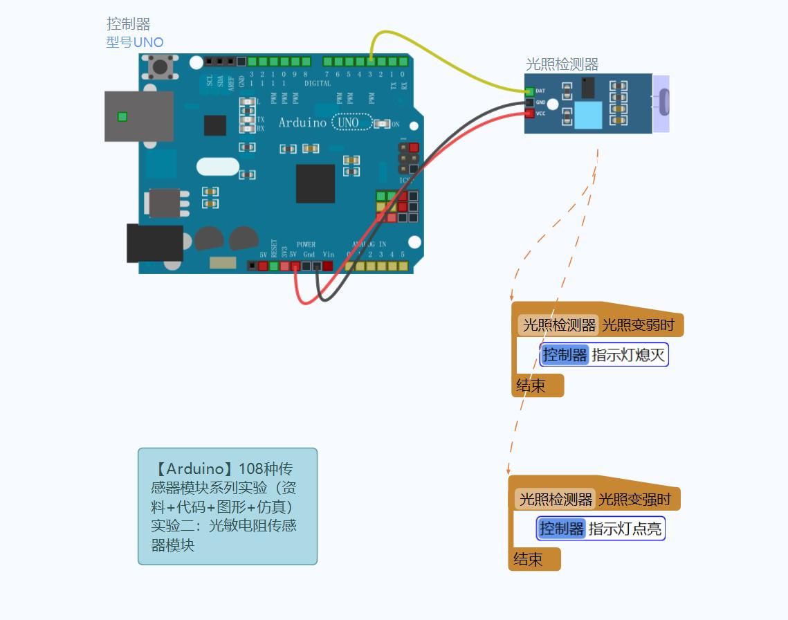
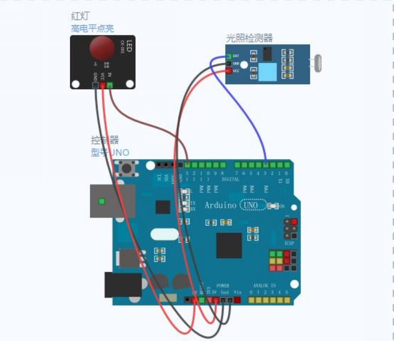
Schematic Diagram of the Simulation Experiment Wiring
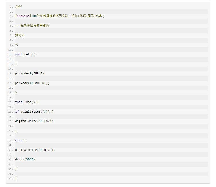
Graphical Programming in Experiments

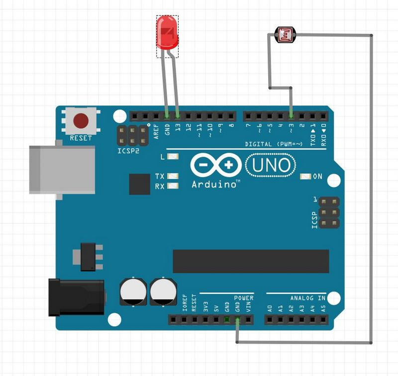
The logical diagram of the experiment
Visual simulation programming, an intuitive and straightforward approach