Arduino Hands-on - L298N Motor Driver Board
【Arduino】168 types of sensor module experiments (data code + simulation programming + graphical programming)
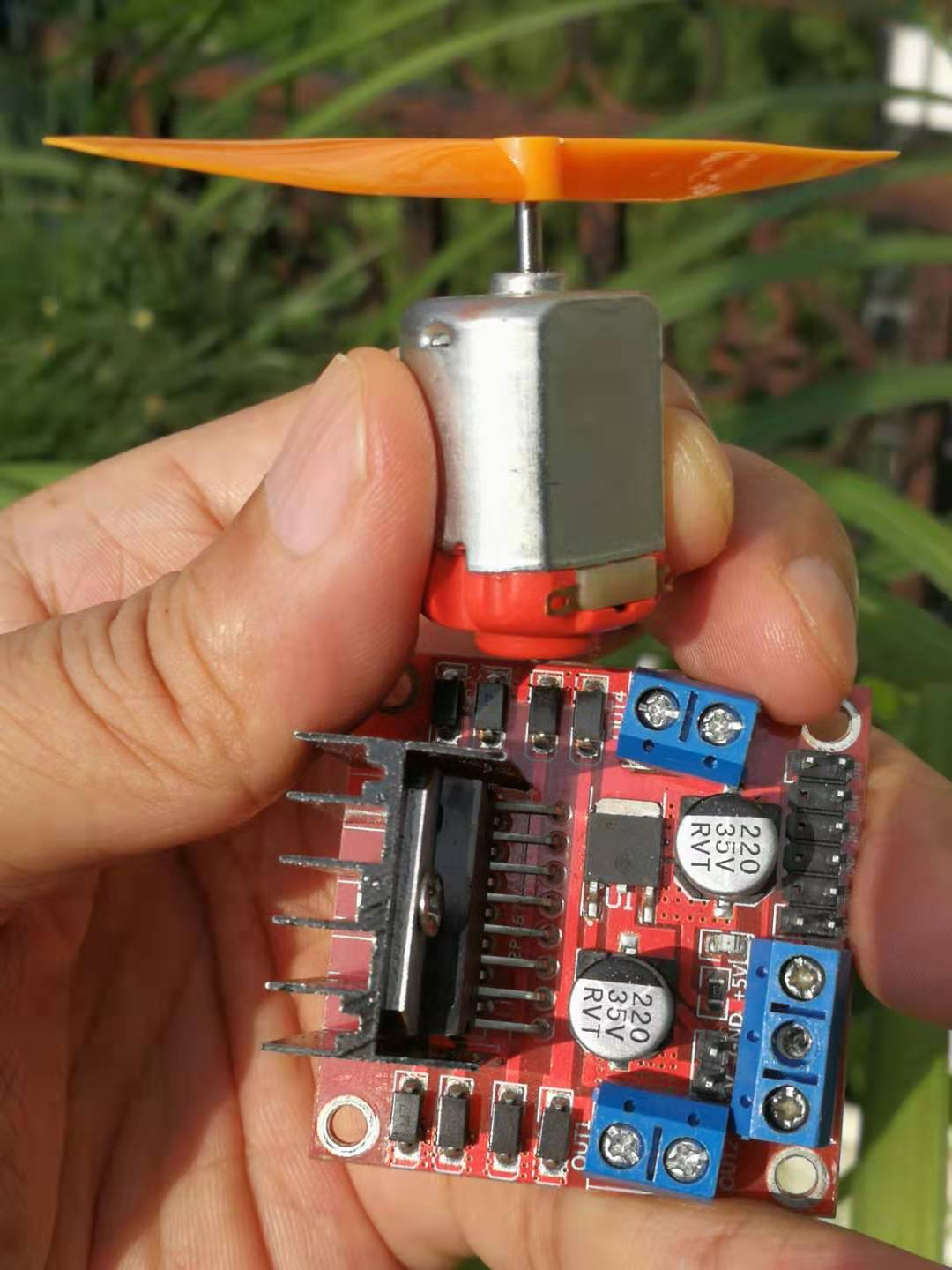
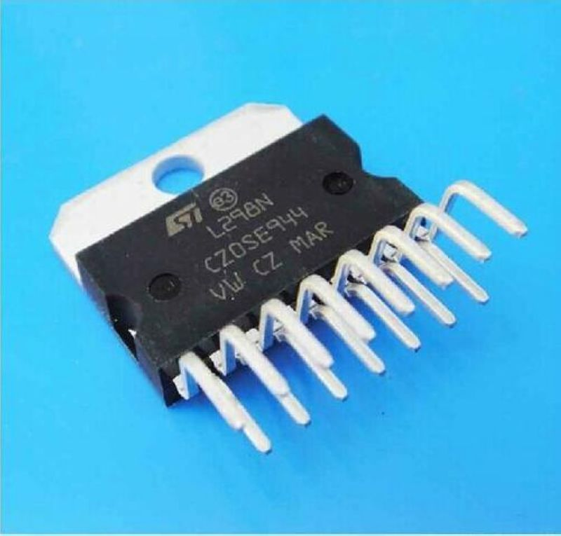
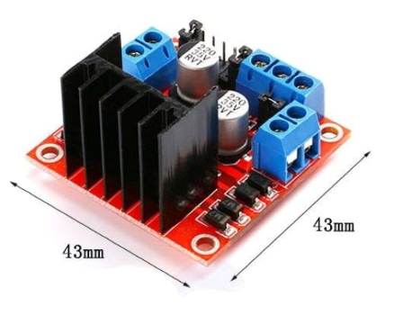
Experiment : L298N motor driver board module DC stepper motor intelligent robot car module
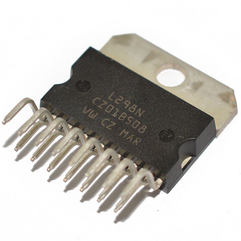
The L298N is a special-purpose driver integrated circuit, belonging to the H-bridge integrated circuit family. The main difference between L298N and L293D lies in its increased output current and enhanced power. With an output current of 2A, maximum current of 4A, and highest operating voltage of 50V, it can drive inductive loads such as high-power DC motors, stepper motors, solenoids, etc. Particularly noteworthy is that its input terminal can be directly connected to a microcontroller, making it very convenient for microcontroller control. When driving a DC motor, it can directly control a stepper motor and achieve forward and reverse rotation simply by changing the logic level at the input terminal.
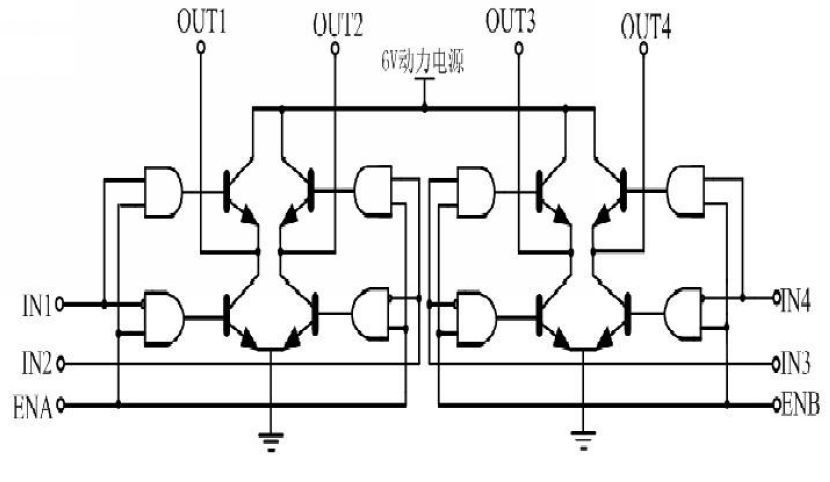
The L298N chip can drive two bipolar motors or one four-phase motor. The output voltage can reach up to 50V, which can be adjusted directly through the power supply. It can receive signals from the microcontroller's IO port and is characterized by a simple circuit design for easy use.
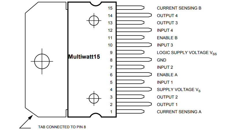
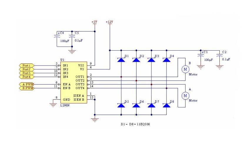
The L298N can accept standard TTL logic level signal VSS, with VSS accepting voltages from 4.5V to 7V. Pin 4 (VS) connects to the power supply voltage, with a VS voltage range for VIH between +2.5V and 46V. The output current can reach 2A, capable of driving inductive loads. Pins 1 and 15 have separate emitter connections for current sensing resistors to form a current sensing signal. The L298 can drive two motors, where OUT1-OUT2 and OUT3-OUT4 can be respectively connected to motors. In this experimental setup, we will be driving a single motor. Pins 5, 7, 10, and 12 connect to input control levels for controlling motor direction. EnA and EnB connect to the control enable terminal for stopping the motor.
L298N Characteristics
Type: Half Bridge
Input Type: Non-Inverting
Number of Outputs: 4
Current - Output / Channel: 2A
Peak Output Current: 3A
Supply Voltage: 4.5V~46V
Operating Temperature: -25°C~130°C
Mounting Type: Through Hole
Package / Case: MulTIwatt-15 (Vertical, Bent and Staggered Leads)
Supplier Device Package: 15-MulTIwatt
Packaging: Tube
Device Model: L298N
Manufacturer: STMicroelectronics
Product Model: MotionMotorControl
Parameters of L298N Motor Driver Module
Driver Chip: L298N Dual H-Bridge DC Motor Driver Chip
Power Supply Range for the Driver Section Terminals Vs: +5V to +35V; If power supply is needed internally on the board, the power supply range is Vs: +7V to +35V
Peak Current for the Driver Section Io: 2A
Power Supply Range for the Logic Section Terminals Vss: +5V to +7V (can be supplied internally at +5V)
Operating Current Range for the Logic Section: 0 to 36mA
Control Signal Input Voltage Range: Low Level: -0.3V ≤ Vin ≤ 1.5V High Level: 2.3V ≤ Vin ≤ Vss
Enable Signal Input Voltage Range: Low Level: -0.3V ≤ Vin ≤ 1.5V (control signal invalid) High Level: 2.3V ≤ Vin ≤ Vss (control signal valid)
Maximum Power Consumption: 20W (temperature T = 75℃)

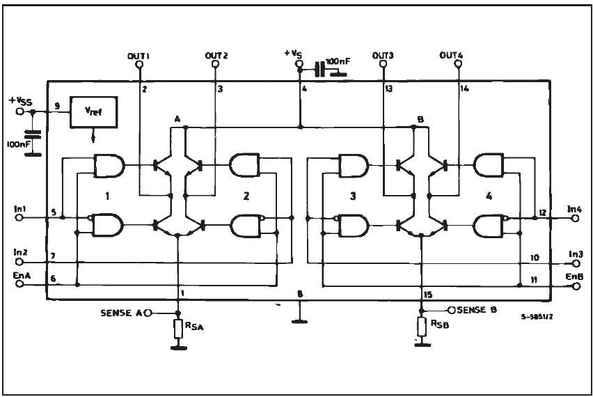
Schematic diagram of L298N motor driver board module
Product features
This module uses ST's L298N as the main driver chip, featuring strong driving capability, low heat generation, and high anti-interference ability. The chip is housed in a 15-pin package. Its main features include: high operating voltage, up to 46V; large output current, peak current can reach 3A, continuous operating current is 2A; rated power of 25W. It contains two H-bridges, high-voltage and high-current full-bridge drivers, which can be used to drive DC motors, stepper motors, relay coils, and other inductive loads using standard logic level signal control. It has two enable control terminals that allow or disable device operation without being affected by input signals, a logic power input terminal for internal logic circuit operation at low voltage, can be connected to an external detection resistor to provide feedback to the control circuit. This chip can drive a two-phase stepper motor or four-phase stepper motor, as well as two DC motors. The module can operate by taking power from the drive power supply section through the built-in 78M05, but to avoid damaging the regulator chip, when using a drive voltage greater than 12V, please use an external 5V logic supply. The module uses large-capacity filter capacitors, freewheeling protection diodes, which can improve reliability.
Performance characteristics of L298N motor driver module:
1: Can achieve motor forward and reverse rotation as well as speed control.
2: Good starting performance with high starting torque.
3: Operating voltage can reach 36V, supporting up to 4A.
4: Capable of simultaneously driving two DC motors.
5: Suitable for applications in robot design and intelligent car design.
Scenario 1: Circuit using L298N to drive two DC geared motors. Pins A and B can be used for PWM control. If the robot project only requires straight forward motion, pins IN1, IN2 and IN3, IN4 can be respectively connected to high and low levels, and only two microcontroller ports are needed to output PWM signals to control the enable terminals A and B, thereby achieving actions like moving straight, turning, accelerating, and decelerating.
Scenario 2: Controlling a two-phase stepper motor with L298. Connect pins IN1, IN2 and IN3, IN4 to a specific port of the microcontroller and output continuous pulse signals. The signal frequency determines the motor speed. Changing the sequence of winding pulse signals enables the motor to rotate in both directions.
Precautions:
1.When your driving voltage (marked as 12V input in the figure, the actual acceptable input range is 7-12V), you can enable the onboard 5V logic supply. After using the onboard 5V power supply, do not apply voltage to the +5V power in the interface, but you can draw out 5V voltage for external use. (This is the conventional application!)
2.When the driving voltage is higher than 12V but less than or equal to 24V (the chip manual states that it can support up to 35V, but based on experience, the L298 generally supports a maximum voltage of 24V in conservative applications!), for example, when driving a motor rated at 18V. First, the jumper cap enabling the onboard 5V output must be removed. Then, externally connect 5V to the 5V output port, where the 5V enable is a control signal with a level of 5V. When this signal is valid and the power supply in the motor drive module is normal, the motor drive module outputs current. Otherwise, even if the power supply is normal, there will be no current on the motor. This voltage supplies power to the L298N internal logic circuit. (This is an unconventional application for high-voltage driving!)
3.If the 5V supplied to the L298N is from a separate power source (i.e., not shared with the microcontroller), then the GND of the microcontroller needs to be connected to the GND on the module. Only in this way can the logic signals coming from the microcontroller have a common reference point. This point is crucial, please take note.

Product User Manual
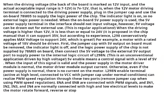
When the driving voltage (marked as 12V input on the back of the board, but can actually accept a range of 7-12V) is between 7V and 12V, and the 12V motor drive terminal is connected to the driving power supply, plug in the jumper cap to use the onboard 78M05 chip for logic power supply. The indicator light will illuminate, eliminating the need for an external logic power supply. After switching to the onboard 5V power supply, do not input voltage to the +5V power supply terminal in the interface, but you can draw out the 5V voltage for external use. (This is the standard application!)
When the driving voltage is higher than 12V but less than or equal to 24V (although the chip manual mentions support up to 35V, based on experience, L298 generally conservatively supports a maximum voltage of 24V!), such as when driving a motor rated at 18V, you must first remove the jumper cap that enables the onboard 5V output, causing the indicator light to go off, no longer using the onboard 78M05 chip for logic power supply. Instead, externally provide 5V voltage to power the internal logic circuit of L298N through the 5V output port. (This is an unconventional application for high-voltage driving!)
The 5V enable signal is a control signal with a level of 5V. When this signal is valid and the power supply for the motor drive module is normal, the motor drive module will output current. Otherwise, even if the power supply is normal, there will be no current on the motor.
The L298N enable terminal (active high, normally jumpered to VCC) can be used to achieve PWM speed control through these two ports (remove the jumper cap when using PWM speed control). Connect ENA and ENB to PWM signals, and connect IN1, IN2, IN3, IN to high or low levels to make the motor rotate forward, reverse, or stop.
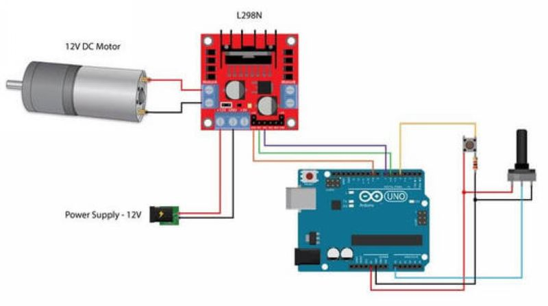
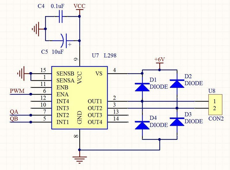
Wiring diagram for L298N motor driver module experiment

Experiment open source code

Experimental field diagram