Arduino Hands-on --- Hall Magnetic Sensor Module
Experiment: Linear Hall Magnetic Force Sensor Module
Hall Effect
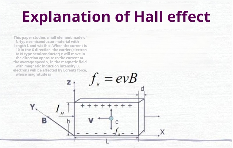
The so-called Hall effect is a type of electromagnetic phenomenon, referring to the physical phenomenon of generating a transverse electric potential difference when a magnetic field acts on the current-carrying carriers in metal conductors or semiconductors. The Hall effect in metals was discovered by American physicist Edwin Hall (1855-1938) in 1879. When an electric current passes through a metal foil, if a magnetic field is applied perpendicular to the direction of the current, a transverse electric potential difference will appear on the two sides of the metal foil. The Hall effect in semiconductors is more pronounced than in metal foils, and ferromagnetic metals exhibit a strong Hall effect below the Curie temperature. The Hall effect can be determined using the left-hand rule.

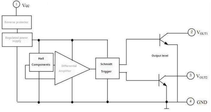
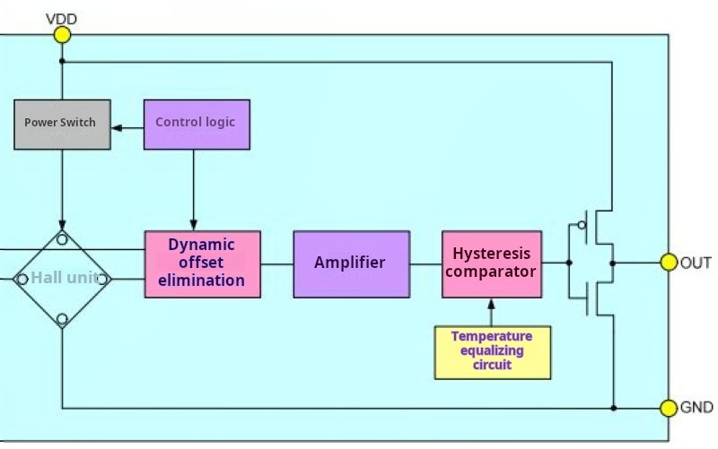
Working Principle of Hall Element
The Hall effect can be utilized to design a variety of sensors. The fundamental relationship for the Hall voltage UH is:
UH = RHIB/d (1)
RH = 1/nq (metal) (2)
Where RH is the Hall coefficient; n is the number of charge carriers or free electrons per unit volume; q is the electron charge; I is the current passing through; B is the magnetic induction intensity perpendicular to I; and d is the thickness of the conductor.
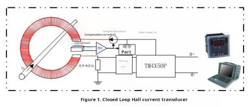
For semiconductors and ferromagnetic metals, the expression for Hall coefficient differs from equation (2), which is omitted here. Due to the presence of a magnetic field around a current-carrying conductor, which is directly proportional to the current in the conductor, Hall elements can be used to measure the magnetic field, thereby determining the magnitude of the current in the conductor. Based on this principle, Hall current sensors can be designed. Their advantages include no electrical contact with the circuit being measured, no interference with the circuit being measured, and no power consumption from the measured power source, making them particularly suitable for high-current sensing.
If a Hall element is placed in an electromagnetic field with electric field intensity E and magnetic field intensity H, a current I will be generated within the element. The Hall voltage and the electric field intensity E produced simultaneously on the element are directly proportional. By measuring the magnetic field intensity of this electromagnetic field, the instantaneous power density P of the electromagnetic field can be determined by P = EH.
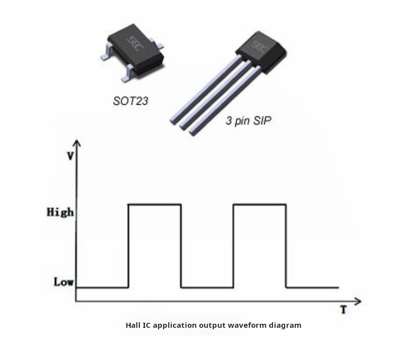
This method can be used to create Hall power sensors. If Hall elements integrated with switches are systematically arranged at predetermined positions on an object, when a permanent magnet mounted on a moving object passes through it, pulse signals can be measured from the sensing circuit. By analyzing the pulse signal sequence, the displacement of the moving object can be detected. Additionally, by measuring the number of pulses emitted per unit time, the speed of the motion can be determined.

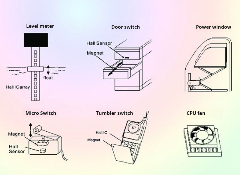
The application of the Hall effect
Hall devices detect changes in magnetic fields and convert them into electrical signals, which can be used to monitor and measure changes in various operating parameters of automobile components. For example, position, displacement, angle, angular velocity, rotational speed, etc., and these variables can be further transformed; they can measure pressure, mass, liquid level, flow rate, etc. The output of the Hall device interfaces directly with the electronic control unit, enabling automatic detection. Modern Hall devices can withstand certain vibrations, operate in a temperature range from -40 degrees Celsius to 150 degrees Celsius, are completely sealed and unaffected by water or oil contamination, making them perfectly suitable for the harsh working environment of automobiles.
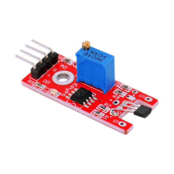
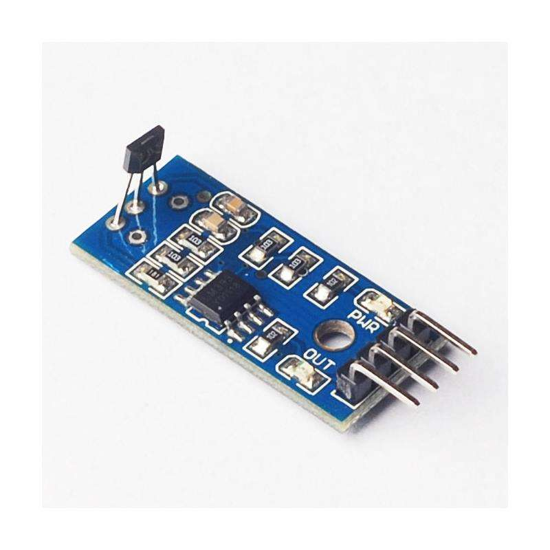
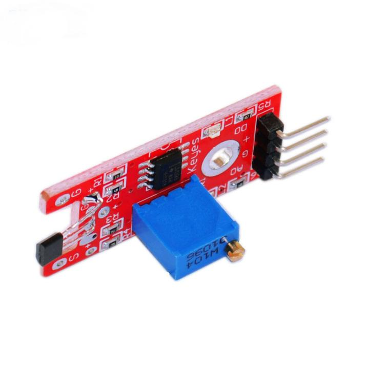
Linear Hall magnetic sensor module
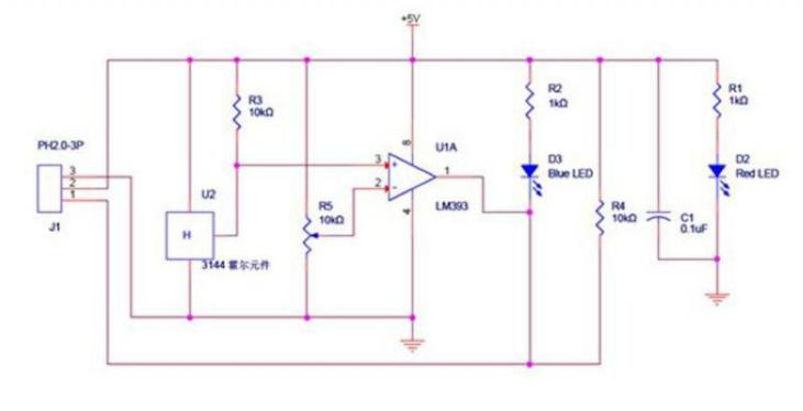
Schematic diagram of the module
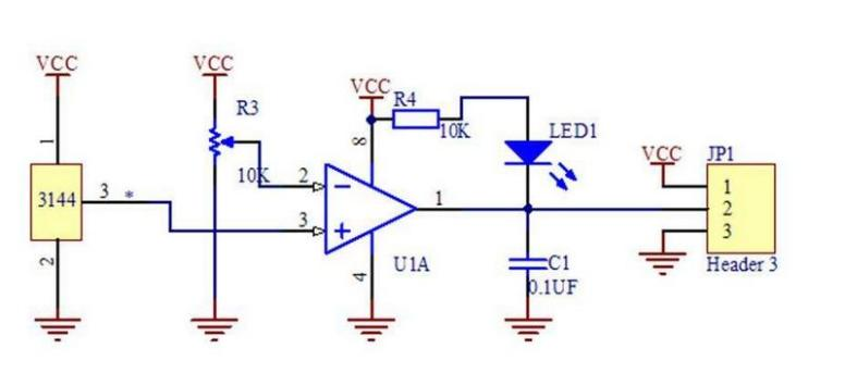
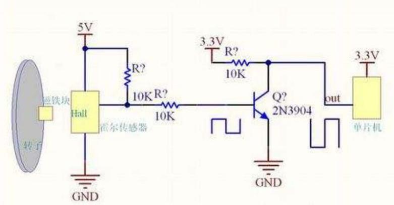
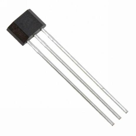
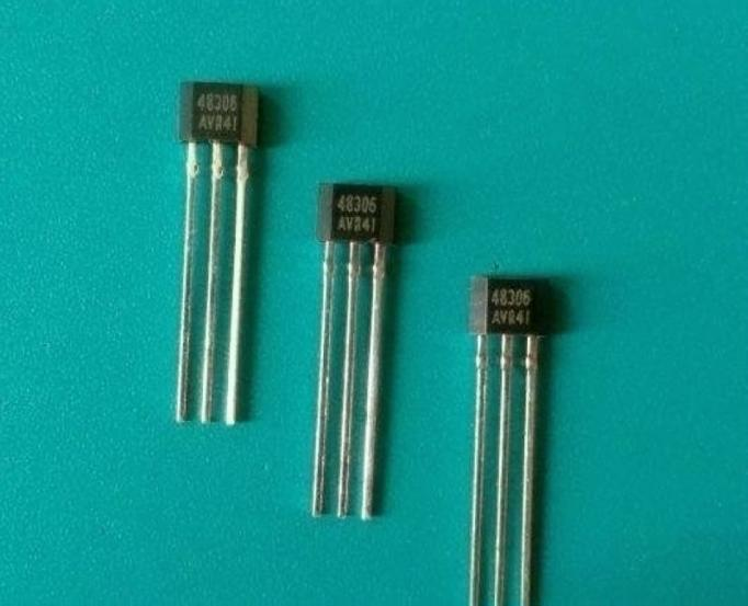
Main chips:LM393, 3144 Hall sensor magnetic induction probe
Operating voltage: DC 5 volts
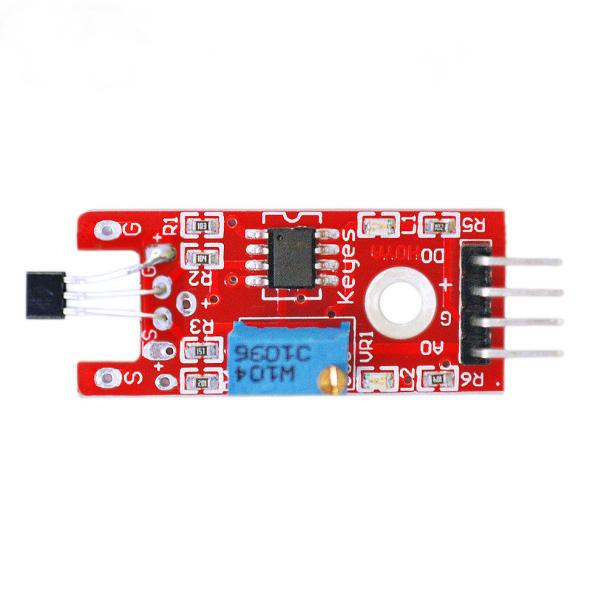
Module Interface Description
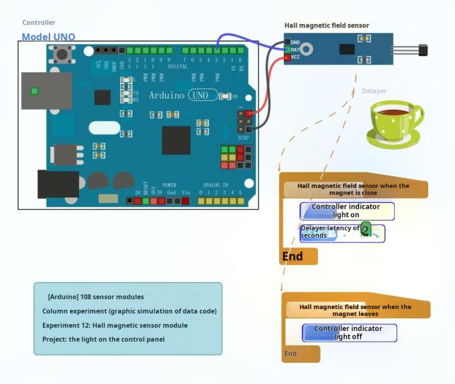
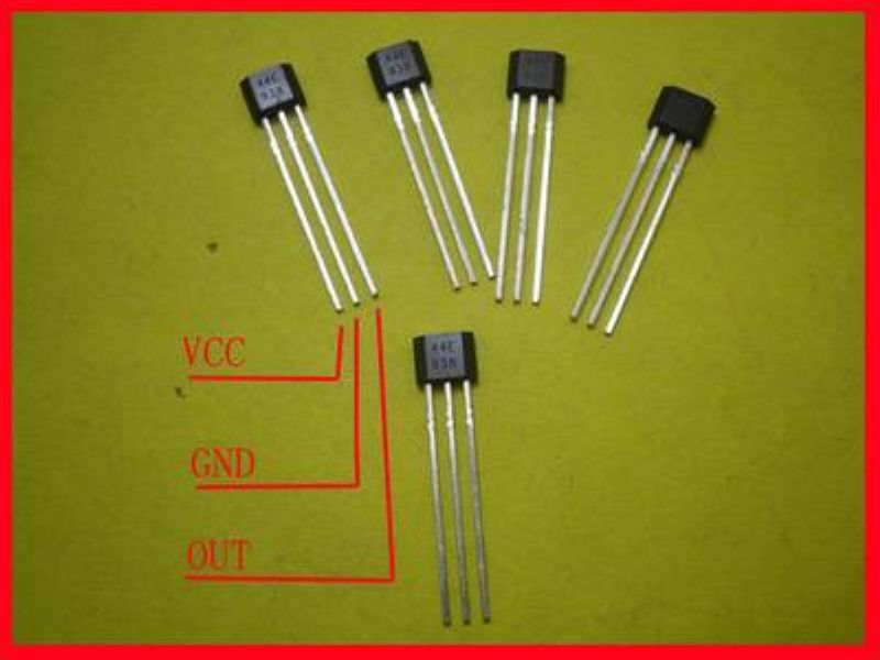
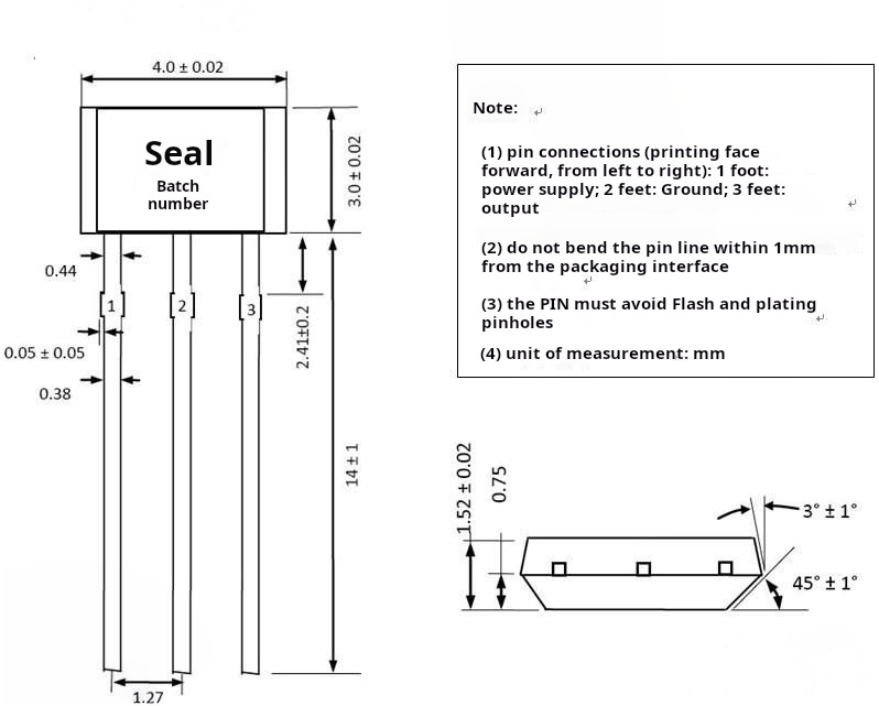
Connect GND to the negative terminal of the power supply (marked as -).Connect VCC to the positive terminal of the power supply, 3.3-5V.DO outputs TTL switch signal (marked as S).Generally, AO pin is not used.
Module Features:
Equipped with signal output indication
With installation holes for easy mounting
Output effective signal is low level
Sensitivity adjustable (fine-tuning)
High sensitivity to magnetic field induction detection
Circuit board outputs switch quantity, directly connectable to microcontroller IO port
Suitable for occasions such as motor speed measurement and position detection
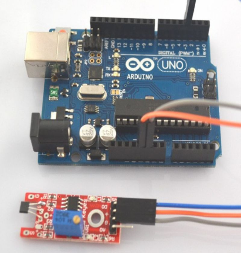
The linear Hall magnetic module with a digital 13 interface comes with an LED. Build a simple circuit to create a magnetic field indicator light.
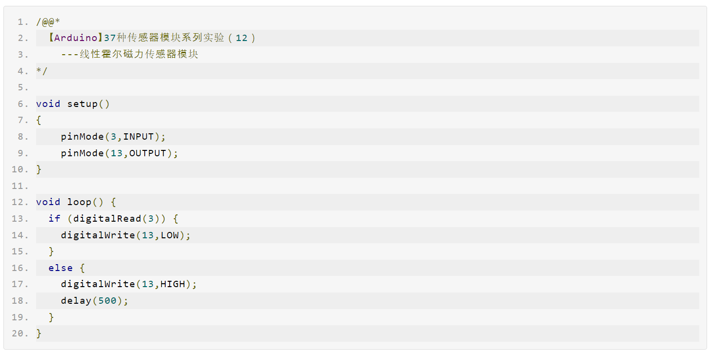
By connecting the linear Hall magnetic sensor to the digital 3 interface, utilizing the built-in LED of digital pin 13, when the linear Hall sensor detects a magnetic field trigger signal, both the module indicator light and the onboard LED of the UNO board will turn on (and stay on for 0.5 seconds), otherwise they will turn off.
Open source code
Open-source graphical programming experiment (Mind+)

Experimental simulation programming (linkboy3.6)