Arduino Hands-on Guide - 8-digit LED Display Module
Experiment:8-Digit LED Display MAX7219 Module (Supports Cascade Connection, Controlled by 3 IO Ports in Serial for Eight Digits)
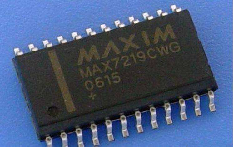
MAX7219 is an integrated serial input/output common cathode display driver that connects a microprocessor to an 8-digit 7-segment digital LED display. It can also be connected to bar graph displays or 64 independent LEDs. It includes an on-chip type B BCD encoder, multiple scanning loops, segment drivers, and an 8x8 static RAM for storing data. Only one external register is used to set the segment current for each LED.
A convenient four-wire serial interface can connect to all common microprocessors. Each data can be addressed without the need to rewrite all displays during updates. MAX7219 also allows users to choose encoding or not for each data. The entire device includes a low-power shutdown mode of 150μA, analog and digital brightness control, a scan limit register that allows users to display 1-8 digits, and a detection mode that lights up all LEDs. Only 3 IO ports are needed to drive 8-digit LED displays! The LED display is non-flickering during operation! Cascade connection is supported!
MAX7219/MAX7221 is an integrated serial input/output common cathode display driver that connects a microprocessor to an 8-digit 7-segment digital LED display. It can also be connected to bar graph displays or 64 independent LEDs. It includes an on-chip type B BCD encoder, multiple scanning loops, segment drivers, and an 8x8 static RAM for storing each data. There is only one external register used to set the segment current for each LED. MAX7221 is compatible with SPI™, QSPI™, and MICROWIRE™, and it features a segment driver with limited return current to reduce EMI (electromagnetic interference). A convenient four-wire serial interface can connect to all common microprocessors. Each data can be addressed without the need to rewrite all displays during updates. MAX7219/MAX7221 also allows users to choose encoding or not for each data. The entire device includes a low-power shutdown mode of 150μA, analog and digital brightness control, a scan limit register that allows users to display 1-8 digits, and a detection mode that lights up all LEDs.
Features:
•l 10MHz continuous serial port
•l Independent LED segment control
•l Selection between decoded and non-decoded digits
•l Low-power shutdown mode of 150μA
•l Digital and analog brightness control
•l High-voltage interrupt display
•l Common cathode LED display driver
•l Segment driver with limited return current to reduce EMI (MAX7221)
•l SPI, QSPI, MICROWIRE serial interfaces (MAX7221)
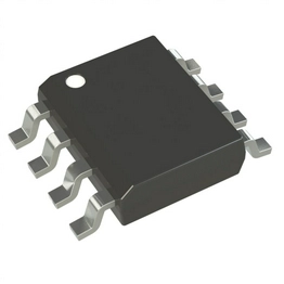
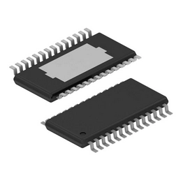
•l 24-pin DIP and SO packaging
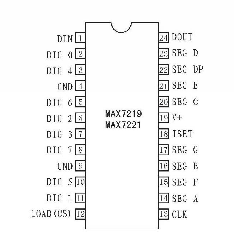
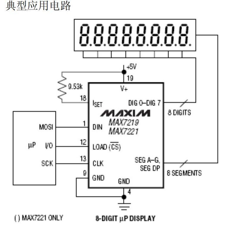
Pin Descriptions:
•l 1 DIN Serial data input port. Data is loaded into internal 16-bit register on rising edge of the clock.
•l 2,3,5-8,10,11 DIG 0–DIG7 Eight data drive lines set the display's common cathode to low. When inactive, pin outputs high for 7219 and presents high impedance for 7221.
•l 4,9 GND Ground (pins 4 and 9 must be grounded simultaneously)
•l 12 LOAD (MAX7219)
•l Load data. The last 16 bits of continuous data are latched at the rising edge of the LOAD pin.CS (MAX7221)Chip select. When this pin is low, serial data is loaded into shift registers. The last 16 bits of continuous data are latched at the rising edge of the CS pin.
•l 13 CLK Clock sequence input. Maximum rate is 10MHz. On the rising edge of the clock, data moves into the internal shift register. On the falling edge, data outputs from DOUT. For MAX7221, clock input is only effective when CS is low.
•l 14-17,20-23
•l SEG 7 Segment and decimal point driver, providing current to the display. When a segment driver is off, this pin is low for 7219 and presents high impedance for 7221.
•l A–SEG G, DP
•l 18 SET Connected to VDD via resistor to increase segment current.
•l 19 V+ Positive voltage input, +5V
•l 24 DOUT Serial data output port, data input from DIN becomes valid at this pin after 16.5 clock cycles. This pin facilitates expansion when using multiple MAX7219/MAX7221.

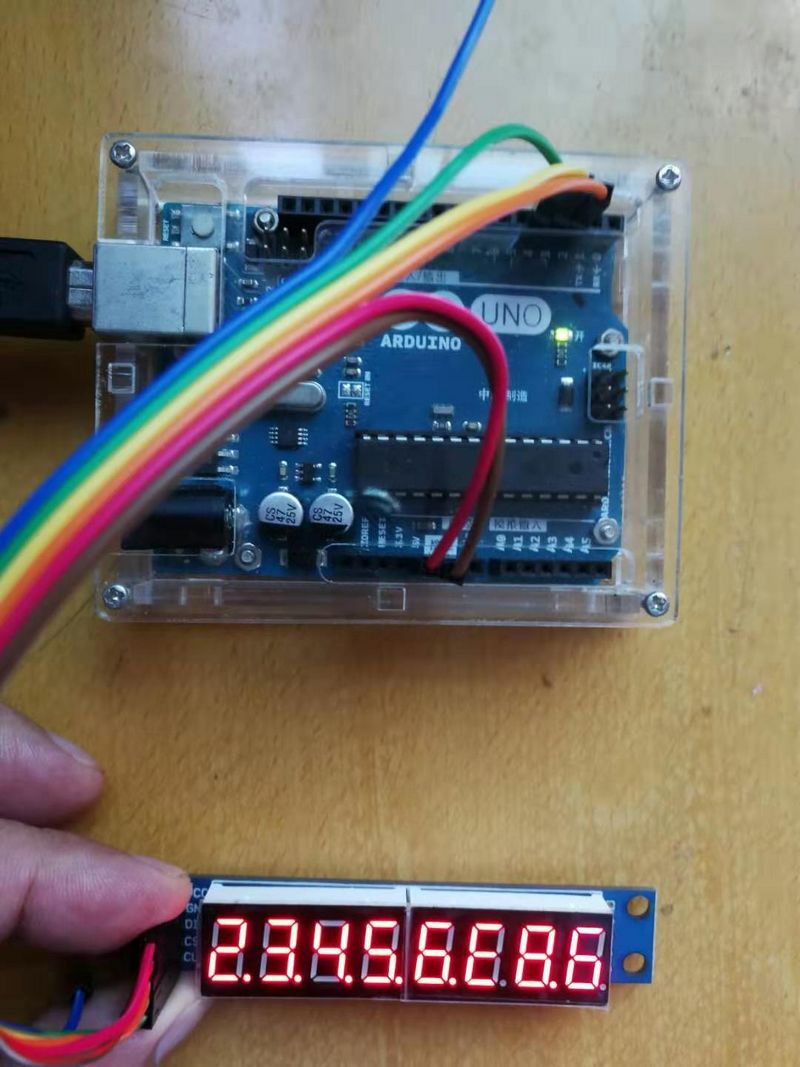
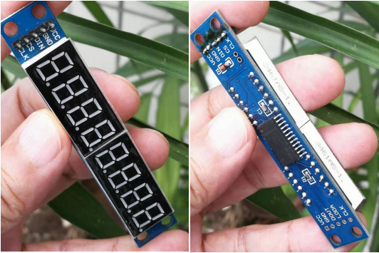
8-Digit LED Display MAX7219 Module (Supports Cascade Connection, Controlled by 3 IO Ports in Serial)
Wiring Instructions (Using the provided program as an example, any IO port can be used, simply modify the port definition in the program):
VCC → 5V
GND → GND
DIN → D2
CS → D3

Module Electrical Schematic

Open-source Experiment Code

Experimental Setup Diagram