A Comprehensive Understanding of Kirchhoff's Laws:Kirchhoff's Current Law (KCL) and Kirchhoff's Voltage Law (KVL)
Gustav Kirchhoff's laws are fundamental and indispensable principles in simple circuit analysis, consisting of two primary laws: Kirchhoff's Current Law (KCL) and Kirchhoff's Voltage Law (KVL).
Kirchhoff's Current Law (KCL) states that the sum of currents entering a node in an electrical circuit is equal to the sum of currents leaving the node. This circuit law is based on the principle of conservation of electric charge density, ensuring that direction of current is conserved at every junction rule in an electrical circuit.Kirchhoff's Voltage Law (KVL) asserts that the total sum of voltages around any closed loop in an electrical circuit is zero. This circuit law follows from the conservation of energy, as the energy gained by conservation of charge moving through voltage sources must be equal to the energy lost across resistive elements in the loop rule.
By applying voltage and current laws, one can effectively understand and analyze the distribution of current flow and voltages in complex circuits. They form a critical foundation for solving electrical circuit problems, often used alongside Ohm's Law, which relates element voltage, current, and resistance in linear circuits.
In this discussion, Kirchhoff's laws will be explored from their theoretical background to practical applications in real-world electrical circuit problems. Additionally, their relationship with Ohm's Law will be examined to provide a comprehensive introduction to these essential concepts. Mastering Kirchhoff's laws is a crucial step in learning about electrical circuits, equipping students and engineers with powerful mathematical tools for effective problem-solving.
Kirchhoff's Laws and Fundamental Electrical Circuit Knowledge
Introduction to Kirchhoff's First and Second Laws
Kirchhoff's laws are essential principles in systematic circuit analysis, consisting of two crucial components: Kirchhoff’s Current Law (KCL) and Kirchhoff’s Voltage Law (KVL).
Kirchhoff’s Current Law (KCL) states that the sum of current branch entering a node is equal to the sum of currents leaving that node. Mathematically, this can be expressed as:
![]()
This law indicates that flow of charge cannot accumulate at a node within an electrical circuit.
Kirchhoff’s Voltage Law (KVL) asserts that the total sum of single voltages around any closed loop in a circuit is zero. This follows from the conservation of energy principle, indicating that the total voltage drop equals the sum of electromotive force (EMF) in the loop:
![]()
This means that the sum of voltage drops and sources around a loop must balance out.
Distinction Between Closed and Open Circuits
Understanding closed and open circuits is vital for circuit analysis, particularly when applying Kirchhoff's laws, which depend on whether a circuit is closed.
Closed Circuits
A closed circuit provides a complete path for electric current to flow from the power source, through various electrical components (such as resistors, capacitors, and inductors), and back to the power source. Kirchhoff’s laws apply to such closed circuits. In a closed circuit, continuous current flow ensures that voltage drops occur across each component in the circuit.
The concept of a closed circuit is central to circuit law design and analysis. Understanding the relationships between current and voltage within these circuits allows for accurate predictions of the behavior of power supplies, resistors in parallel, and other electrical components. Furthermore, closed circuits are crucial for assessing circuit performance and diagnosing issues.
Open Circuits
An open circuit is one where the conductive path is interrupted, preventing the flow of current. This interruption can result from an open switch, physical disconnection, or breakage for any reason.
While Kirchhoff's laws do not directly apply to open circuits, they play an important role in analyzing systems containing open circuits. When a circuit malfunctions or is designed to use open circuits intentionally, Kirchhoff's laws become indispensable powerful tools. Open circuits often cause operational issues, making them critical in troubleshooting and diagnostics. Additionally, the concept of open circuits is applicable in designing switch-controlled circuits and temporary interruptions.
Overall, mastering Kirchhoff's laws and understanding the differences between closed and open circuits provide a solid foundation for effective electrical circuit analysis and problem-solving in electronics.
The Role of Kirchhoff's Laws in Voltage and Current Measurements
Voltage measurement is a pivotal aspect of circuit analysis, where Kirchhoff's laws play a fundamental role.
Basics of Voltage Measurement
Voltage measurement involves determining the potential difference between two points in an electronic circuit. This is typically done using a voltmeter, which must be connected in parallel across the points of interest to obtain an accurate reading.
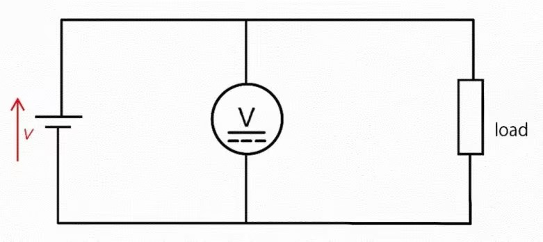
Application of Kirchhoff’s Voltage Law (KVL)
Kirchhoff’s Voltage Law (KVL) posits that the sum of electrical voltages around any closed loop within a circuit equals zero. This principle is crucial for measuring and calculating voltages throughout any loop within the circuit network.
![]()
When measuring voltage rise, KVL allows for the determination of unknown voltages by using known voltage drops across other components. By applying KVL, one can verify the integrity of voltage measurements and ensure that all sources and drops conform to the law.
Current measurement and circuit analysis are vital for evaluating circuit node performance and ensuring safety.
Current measurement entails determining the intensity of current flowing through a particular section of a parallel circuit. This is usually accomplished using an ammeter, which must be connected in series with the section being measured to accurately capture the current flow.
Kirchhoff’s Current Law (KCL) and Circuit Analysis
Kirchhoff’s Current Law (KCL) states that the total current entering a node is equal to the total current leaving that node.
![]()
This law enables detailed analysis of current distribution at any point within a complicated circuit and aids in interpreting the results of current measurements. By employing KCL, one can gain insights into how current is distributed throughout the circuit, thereby assessing its functionality and identifying potential issues.
In summary, Kirchhoff's laws provide essential frameworks for both voltage and current measurements, facilitating comprehensive circuit analysis and ensuring accurate evaluation of electronic systems. These principles help engineers and technicians maintain efficient and safe operation of electronic devices.
Examples of Applying Kirchhoff's Laws and Calculation Methods
Let's break down a step-by-step example using Kirchhoff's laws for circuit calculations.
Example Calculation
Consider a simple circuit with three resistors, R1, R2, and R3, connected in series with a voltage source Vs. The goal is to determine the voltage across each resistor.
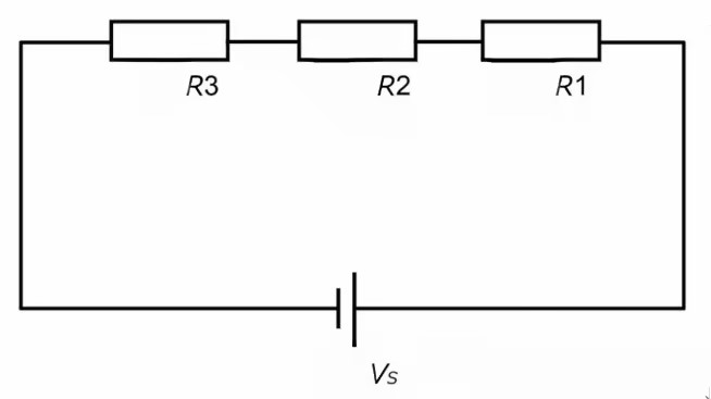
Analyze the Circuit:
1.Identify components:
Voltage Source (Voltage: Vs)
● Resistor 1 (Resistance: R1)
● Resistor 2 (Resistance: R2)
● Resistor 3 (Resistance: R3)
2.Apply Kirchhoff’s Voltage Law (KVL):
● According to KVL, the sum of the voltages around a closed loop equals zero.
● For this series circuit: ( Vs = V1 + V2 + V3 )
● Where V1, V2, and V3 are the voltages across resistors R1, R2, and R3, respectively.
3.Apply Ohm’s Law:
● Use Ohm’s Law for each resistor: ( V = I*R )
● Hence, ( V1 = I* R1 ), ( V2 = IR2 ), ( V3 = I * R3 )
4.Calculate:
Substitute the values into the KVL equation to find the current I:
( Vs = I * R1 + I * R2 + I * R3 )
Calculate each voltage:
● ( V1 = I * R1 )
● ( V2 = I * R2 )
● ( V3 = I * R3 )
5.Verify the Equation:
Ensure the total voltage drop equals the source voltage: ( V1 + V2 + V3 = Vs )
The calculated voltages confirm that the voltage drops across the resistors equal the source voltage in a series circuit.
Applying Kirchhoff’s Laws to Complex Circuits
For more complex circuits with multiple sources and resistors, consider the following scenario:
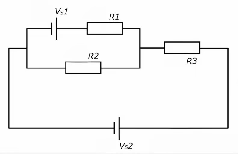
Let's consider a circuit that includes multiple voltage sources and resistors, which will demonstrate the advanced application of Kirchhoff's laws in a more complex setup.
● Voltage Source 1 (Voltage: Vs1)
● Voltage Source 2 (Voltage: Vs2)
● Resistor 1 (Resistance: R1)
● Resistor 2 (Resistance: R2)
● Resistor 3 (Resistance: R3)
Circuit Configuration:
● Vs1 and R1 are in series.
● R2 is parallel to this combination.
● This entire setup is in series with R3.
● Finally, Vs2 is connected after R3.
Circuit Equations:
● Loop 1 (Vs1, R1, R2): ( Vs1 - I1* R1 - I2* R2 = 0 )
● Loop 2 (Vs1, Vs2, R3): ( Vs1 - I3* R3 - Vs2 = 0 )
● Loop 3 (Vs2, R2, R3): ( Vs2 - I2* R2 - I3*R3 = 0 )
Where ( I1, I2, I3 ) represent currents in respective parts of the electric circuit.
Steps for Analysis:
1.Identify Circuit Elements: Recognize all sources, resistors, nodes, and loops in the circuit.
2.Apply Kirchhoff’s Laws: Use KVL for loops and KCL for nodes as needed.
3.Set Up Simultaneous Equations: Formulate differential equations based on Kirchhoff’s laws.
4.Calculate: Solve the equations to find unknown currents and voltages.
By following these steps, complex circuits can be systematically analyzed, allowing for accurate determination of electrical parameters within the circuit over time.
Potential Difference and Electromotive Force: Extensions of Kirchhoff's Laws
What is Potential Difference? Its Relation to Kirchhoff's Laws
The concept of potential difference is fundamental in flow of electricity and is closely related to Kirchhoff's laws.
Potential difference refers to the difference in electric potential (the state of electrical energy) between two points, indicating the work done when a charge moves from one point to another. It is measured in volts (V) and can be expressed by the formula:
[ V = \frac{W}{Q} ]
Where:
● ( V ) represents the potential difference,
● ( W ) represents work done,
● ( Q ) represents charge.
Understanding potential difference is crucial for applying Kirchhoff's laws to determine voltage distribution within circuits. For instance, in circuits containing multiple sources and resistors, Kirchhoff's laws help ascertain the potential differences across various electronic components. By utilizing these laws, one can accurately map out how the potential provided by electric power sources is distributed throughout the digital electronic circuit.
Comprehensive Understanding of Electromotive Force and Kirchhoff's Laws
Electromotive force (EMF) is the potential difference generated by a power source, and understanding its interaction with Kirchhoff’s laws is essential.
EMF is the measure of energy supplied by a source (such as batteries or generators) in creating a potential difference across a circuit. It quantifies the ability of a source to impart energy to the circuit, also measured in volts (V). When charges move due to the electric field created by the source, EMF is produced.
When combined with Kirchhoff’s laws, EMF provides insights into how energy supplied by sources interacts with the consumption of energy across different elements (such as resistors and capacitors) in a circuit. The voltage drop across circuit components (representing energy consumption) balances with the EMF provided by the source. This balance is vital for circuit design, analysis, and troubleshooting.
By understanding the intricate relationships between potential difference, EMF, and Kirchhoff’s laws, engineers and technicians can effectively predict circuit behavior, ensure efficient operation, and diagnose potential issues in electrical systems. This comprehensive knowledge forms the backbone of successful circuit management and innovation.