What is an Inductor?
1. Inductor Description
What is an Inductor? An ideal inductor is an electronic component capable of converting electrical energy into magnetic energy and storing it. Its structure resembles that of a transformer but consists of only one winding capacitance. Inductors possess inductance value, which primarily resists changes in electric current. When connected to an electrical circuit without any current flow, an ideal inductor will attempt to impede the initial flow of current; conversely, if there is electric current flowing, it will strive to maintain steady current flow when the magnetic circuit is broken. Inductors are also known as chokes, reactors, or dynamic reactors.
2. Evolution of Inductor
The earliest inductor, an iron-core coil, was used by Michael Faraday in 1831 to discover electromagnetic induction. In 1832, American scientist Joseph Henry published a paper on mutual induction phenomena. The standard unit of inductance value is named "henry" (H) in his honor. By the mid-19th century, inductors found practical applications in electronic devices like telegraphs and telephones.
Notable inductors include those used by Heinrich Hertz in 1887 and Nikola Tesla in 1890 during their experiments, famously known as Hertz coils and Tesla coils, respectively.
3. Functions and Applications of Inductors
An ideal inductor serves several functions in electronic circuits, including filtering, oscillation, delay, and notch filtering. They are also employed for signal selection, noise filtration, initial current stabilization, and suppression of electromagnetic interference. A common use of variable inductors is in LC filter analog circuits alongside capacitors.
While capacitors allow AC through but block DC, inductors do the opposite—they permit DC flow while obstructing AC. In an LC filter circuit diagram, DC carrying electromagnetic interference signals passes through the variable inductor, which dissipates these signals as heat, purifying the DC initial current. The high-frequency passive components are more effectively blocked by the inductor's impedance, suppressing higher-frequency interference signals.
Due to their ability to impede AC while allowing DC to pass, adjacent inductors are primarily used to isolate AC signals, perform filtering, or form resonant circuits with capacitors and resistors.
4. Structure of Inductors
Real inductors typically consist of a framework, winding, shield, encapsulation magnetic material, magnetic field, or laminated iron core.
Framework: This refers to the support structure around which the induction coil is wound. Larger fixed or adjustable inductors often have enamel-coated or silk-covered insulated wire wound on a framework, with a magnetic flux or iron core material inserted to enhance mutual inductance value. Frameworks are usually made from plastic, bakelite, or ceramic and come in various shapes based on necessity. Small inductors (like color-coded inductors) might skip the framework, instead wrapping wire directly around the core. Air-core inductors, used in high-frequency circuits, with immunity requirement of no core material, framework, or shield, being wound around a mandrel and spaced apart before removing the mold.
Winding: A winding is a set of spiral coil pattern with specific functions, forming the primary electrical component of an inductor. There are single-layer and multi-layer windings, with single-layer windings further divided into tight-wound (coils touch each other) and spaced-wound (gaps between coil forms) types. Multi-layer windings can be layer-by-layer, randomly wound, or honeycomb-patterned.
Magnetic Core and Rod: Typically made from magnetic materials like nickel-zinc ferrite (NX series) or manganese-zinc ferrite (MX series), they come in various shapes such as "I," cylindrical, hat, "E," or pot cores.
Iron Core: Made from type of material used like silicon steel sheets or permalloy, usually in an "E" shape.
Shield: To prevent an inductor’s magnetic field from affecting other circuits and basic components, a metal shield may be employed, such as in semiconductor radio oscillator coils. This shield, however, increases core loss and reduces the Q factor.
Encapsulation Material: Once wound, some basic inductors (e.g., color-coded inductors) are sealed with materials like plastic or epoxy resin.
5. Classification of Inductors
Inductors come in various forms, most commonly crafted by winding enamel-coated wire around ferrite cores. In certain shielded inductors, the coil is completely enclosed within the ferrite material. Some inductive components feature adjustable cores, allowing the mutual inductance value to be modified accordingly.
For smaller inductors, they can be directly etched onto printed circuit boards (PCBs) through a process that lays down spiral tracks. Similarly, low-value inductors can be fabricated using processes akin to those for transistors in integrated circuit requirement. In these applications, aluminum interconnects are frequently used as conductive materials.
Regardless of the method employed, practical constraints often favor circuits known as "gyrators," which utilize capacitors and active components to replicate the characteristics of inductive elements. Inductors designed for high-frequency isolation frequently consist of a wire threaded through a electromagnetic field or bead, providing effective impedance against unwanted frequencies.
Small Inductors
Small fixed inductors are typically constructed by directly winding enamel-coated wire around a electric field. They are primarily used in circuits for filtering, oscillation, notch filtering, and delay. These inductors come in both sealed and unsealed packaging forms, with each form available in either vertical or horizontal structures.
Adjustable Inductors
Common types of adjustable inductors include oscillation coils for semiconductor radios, line oscillation coils for televisions, linearity coils, intermediate frequency notch coils, frequency compensation coils for audio equipment, and blocking coils. These are designed to allow tuning and adjustment within their respective applications.
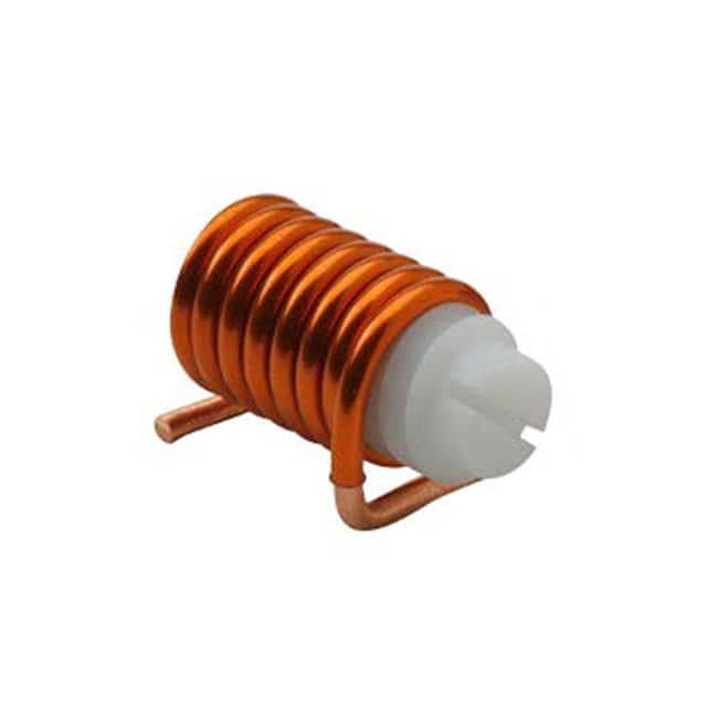
Adjustable Inductors:JLC03E048TRSM
Choke Inductors
Choke inductors are used in electric circuits to obstruct the path of AC initial current passing. They are categorized into difference between chokes,like high-frequency choke coils and low-frequency choke coils, depending on the specific application and the frequencies they are intended to block.
6.The Characteristics of Inductors
The characteristics of inductors are the opposite of those of capacitors. Inductors allow direct current (DC) to pass through easily while blocking alternating current passing. When a DC signal flows through the coil, the only resistance encountered is the inherent resistance of the wire itself, which results in a minimal voltage drop. However, when an AC current signal passes through the coil, the compact inductor generates a self-induced electromotive force (emf) that opposes the direction of the applied voltage source, thereby impeding the passage of AC.
Thus, the primary characteristic of an inductor is that it permits DC while obstructing AC. The higher the self-resonant frequency of the AC, the greater the impedance offered by the coil shape. Inductors frequently work alongside capacitors in electric circuits to form LC filters and LC oscillators. Moreover, the properties of inductors are utilized in the creation of devices such as chokes, transformers, and relays.
Allowing DC Passage: Inductors act as a conductive path for DC low-frequency signals. If the resistance of the inductor's wire is negligible, DC can flow "unhindered" through the inductor. In resonant circuit analysis, the resistance of the coil shape against DC is often so minor that it is disregarded.
Blocking AC: When AC passes through an inductive coil, the inductor presents a significant impedance to the AC signal. This impedance, known as inductive reactance, is what hinders the flow of AC through the coil.