How to Use an CAN Bus Oscilloscope to Analyze Issues in New Energy Vehicles
Embedded systems are experiencing rapid growth in the automotive industry. Many vehicle designs utilize the Controller Area Network (CAN) for communication between electronic control units (ECUs) and between ECUs and sensors, actuators, and displays. Subsystems ranging from braking systems to infotainment systems offer real-time communication capabilities.Engineers frequently use CAN bus oscilloscopes to capture data. Unlike communication acquisition cards, handheld oscilloscopes can perform protocol analysis while also providing insight into the physical layer transmission, thereby assisting engineers in understanding and analyzing the bus from both software and hardware perspectives.
What is meaning of CAN Bus?
The CAN is a bus structure initially created for automotive use, yet it has proven useful in various other sectors too. The CAN bus functions using balanced (differential) two-wire interfaces on various cables, based on automotive applications. This standard outlines unsimilar data rates, with 1 Mb/s being the highest rate for CAN. The newest version, CAN FD boosts the transmission speed to as high as 10 Mb/s and lengthens the maximum size of the payload data field. To preserve the quality of the analog signal, the bus needs 120Ω terminators at each end of the cable to guarantee impedance matching.
Since its introduction in the 1980s, the CAN bus has been used for transmitting data between ECUs and with vehicle ignition sensors.

CAN Bus Tester in Connected Vehicles
In recent years, the quantity of data generated in vehicles has significantly increased and will be so in future. Today, many vehicles contain over 80 ECUs connected through various bus networks.
Increased integration among automotive subsystems means that beiside sensors and actuator signals, numerous ECUs communicate concurrently over more buses. For example, it's very common for ECUs to communicate via CAN (for critical systems) and LIN (for lower-priority controls like windows and mirrors).
Can Bus Diagnostics
Ensuring the correct configuration of the CAN bus is crucial since driver safety relies on these systems communicating properly. Therefore, using appropriate tools to troubleshoot the CAN bus becomes essential.
How to Debug and Decode CAN Bus Protocol with an Oscilloscope
CAN Bus Triggering
When triggering the CAN bus, using the default rising edge trigger may result in waveform jitter and unstable triggering in the middle of the screen. A bus trigger can be used in this situation.
Can Bus Signal Setting
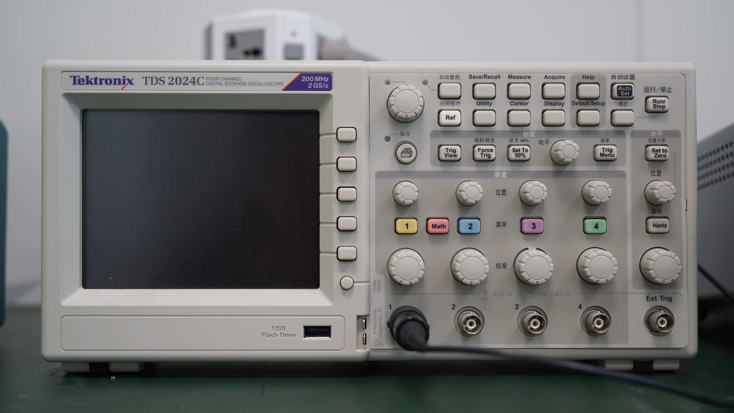
On Tektronix oscilloscopes that have CAN decoding and triggering features, pressing the bus button on the front panel enables you to configure the CAN bus decoding details of the oscilloscope. To ensure precise decoding, fundamental parameters like the CAN standard, random signal type, input channel, bit rate, voltage level, and sampling point (represented as a percentage of bit time) must be provided. The CAN bus functions as a differential signal. An oscilloscope is capable of decoding the bus with single-ended probes; however, employing differential probes can improve signal clarity and resistance to noise.
Understanding CAN/CAN FD Bus Decoding Information
The decoded CAN signal is displayed as a bus waveform and event table, with elements of the decoded CAN message shown in different colors. For engineers, a timeline format with timestamps might be more useful, as it easily correlates with software lists and provides a simple calculation of transmission speeds. The event table also links to the waveform display. By clicking on messages in the decode table, you can automatically jump to the corresponding waveform, which can be enlarged using knobs to see the relevant bus signal and the generated bus decodes.
DBC File Parsing
.dbc files describe CAN bus communication data, containing protocol data and their specific meanings. During vehicle road testing, it's necessary to perform real-time DBC parsing of CAN message data to pinpoint issues. .dbc files convert CAN messages into motor status and their current state values for engineers to conduct real-time analyses and debugging.
CAN Bus Testing
Comprehensive CAN/CAN FD bus triggering features include the following trigger types:
1.Frame Start: Position of frame structure start
2.Frame Type: Data frame, remote frame, error frame
3.Identifier: Standard format with 11-bit identifier (ID), extended format with 29-bit ID
4.Data: Actual content of data; a frame can send 0 to 8 bytes of data
5.Frame End: Position of frame structure end
6.Error: Examples include ACK errors, bit stuffing errors, etc.
Different trigger positions can be selected based on actual needs for quick data positioning and analysis.
CAN Bus Data Search
On Tektronix oscilloscopes equipped with CAN/CAN FD decoding, CAN bus activity can be searched. The search function can find all bus events meeting specific search conditions and determine how many occurrences there are.
DBC Data Search
In addition to searching hex values and binary values, when using symbol decoding, a .dbc file can be loaded. Parsed data and information can be automatically searched.


