
Understanding Transmission Gates: A Versatile Building Block in Electronics
If you’ve ever wondered how electronic circuits manage to switch signals with precision and efficiency, the transmission gate is a key player worth knowing about. This clever little component, found in everything from simple logic circuits to complex integrated systems, acts as a solid-state switch that can handle both digital and analog signals. In this article, we’ll dive into what makes transmission gates tick, their advantages, where they shine in real-world applications, and how they stack up against alternatives like pass transistors.
What Exactly is a Transmission Gate?
At its core, a transmission gate is a bilateral switch made up of two complementary transistors: an nMOS transistor and a pMOS transistor. These transistors are wired in parallel, with their source terminals connected to form the input node and their drain terminals linked to create the output node. The magic happens at the gate terminals, where a control signal—along with its complement—tells the gate whether to act as a closed switch or an open one.
When the gate control voltage turns both transistors on, current flows freely from input to output, passing digital signals or analog signals with minimal fuss. Flip the control input to off, and the gate blocks the signal entirely. This ability to conduct in both directions—thanks to its bilateral operation—sets it apart from simpler switches, making it a go-to for designs needing flexibility.
Think of it like a double-door gate in your backyard: one door (nMOS) opens for low voltages, while the other (pMOS) handles the high ones. Together, they ensure the full range of signal levels gets through without a hitch.
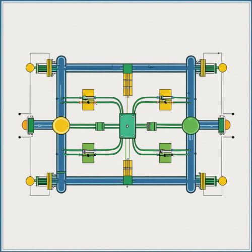
Fig 1. Simplified Circuit Diagram of a Transmission Gate
Why Choose Transmission Gates?
So, what’s the big deal about transmission gates? They bring a lot to the table compared to other options like pass transistors or traditional logic gates. Here’s why engineers love them:
● Low Channel Resistance: When on, the parallel nMOS and pMOS combo keeps channel resistance super low, so your output voltage stays close to the input voltage.
● No Voltage Drop: Unlike a pass transistor, which can lose some voltage due to threshold voltage, transmission gates pass the full logic level—from ground to the supply rail.
● Bidirectional Switch: Need a signal to flow either way? This bilateral CMOS switch has you covered, perfect for analog switch or multiplexer designs.
● Power Efficiency: In static operation, they sip power, only drawing current during switching.
Take a 2-to-1 multiplexer, for example. With transmission gates, you can select between two input signals cleanly and efficiently, no distortion needed. That’s the kind of advantage that makes them stand out.
Table 1. Comparison of Transmission Gate and Pass Transistor
|
Feature |
Transmission Gate |
Pass Transistor |
|---|---|---|
|
Voltage Drop |
None (full logic level passed) |
Yes (due to threshold voltage) |
|
Channel Resistance |
Low (parallel nMOS and pMOS) |
Higher (single transistor) |
|
Power Consumption |
Low (only during switching) |
Low (similar) |
|
Bidirectional |
Yes |
Yes |
|
Complexity |
Moderate (two transistors + control logic) |
Simple (one transistor) |
|
Best For |
Precision, full-range signal switching |
Simple, low-cost designs |
Where Do Transmission Gates Shine?
Transmission gates pop up all over the place in electronics. Here are some spots where they really flex their muscles:
● Logic Circuits: They’re great for building compact XOR gate circuits or even a 4-transistor XOR gate, cutting down on component count compared to a NAND-gate based implementation.
● multiplexers: A 2-to-1 multiplexer circuit using transmission gates is a classic. Two gates, some complementary control voltages, and boom—you’ve got a tidy digital multiplexer.
● D-type Latches: Pair them with feedback inverters, and you’ve got a compact D latch for memory blocks in digital circuit applications.
● Analog Applications: As an analog gate, they switch signals in application circuits like sample-and-hold setups without messing up the waveform.
● Security Applications: Ever heard of hot insertion? Transmission gates can isolate signals in systems where components swap in and out without powering down.
Transmission Gates vs. Pass Transistors
Now, let’s pit transmission gates against their cousin, the pass transistor. A pass transistor—say, a lone N-channel mosfet—is simpler, sure. It uses a single transistor to pass a signal, controlled by its gate-source voltage. But here’s the rub: it suffers from a voltage drop. If the input voltage is high, the output might not reach it fully due to that pesky threshold voltage.
A transmission gate, though? It sidesteps that problem entirely. The nMOS handles low voltages, the pMOS takes the high ones, and together they deliver the full range—no negative voltage issues, no compromise on drain voltage. Plus, the channel enhancement from both transistors means less resistance than a pass transistor switch.
The trade-off? Transmission gates need two transistors and complementary gate input, which might complicate a transistor-level implementation. For a quick-and-dirty logic function, a pass transistor might do. But for precision—like in CMOS digital integrated circuits—transmission gates win hands-down.
Table 2. Pros and Cons of Transmission Gates vs. Pass Transistors
|
Aspect |
Transmission Gate |
Pass Transistor |
|---|---|---|
|
Pros |
- Full voltage swing |
- Simpler design |
|
- Low resistance |
- Fewer components |
|
|
- Bidirectional |
- Lower cost |
|
|
Cons |
- More complex (two transistors) |
- Voltage drop |
|
- Requires complementary control signals |
- Higher resistance |
|
|
Ideal Use Case |
High-precision, full-range switching |
Low-cost, non-critical applications |
Designing with Transmission Gates: What to Watch For
Ready to use a transmission gate in your next project? Here are some practical tips to keep in mind:
● Gate Signal Timing: The control gates need spot-on timing. A glitch in the complementary control voltages could leave your gate half-open, leaking drain current.
● Power Supply Noise: In analog applications, watch out for power supply noise problems. Keep that positive supply voltage potential stable.
● Signal Levels: Don’t push signals beyond the supply rail, or you risk damaging the active devices.
● Input to Output Capacitance: High-speed designs need to account for this, as it can slow things down.
Pro Tip: When designing with transmission gates, always simulate the control signal timing to avoid partial conduction states, which can lead to signal degradation or increased power consumption.
Imagine you’re building an 8-bit transmission gates setup for a data bus. A little care with gate decoder placement and channel deskew ensures your signals stay crisp and clean.
Wrapping It Up
“Transmission gates are the Swiss Army knife of digital and analog circuit design. Their ability to switch signals without distortion makes them indispensable in everything from basic logic to high-speed data paths.”— Dr. Emily Chen, Professor of Electrical Engineering, Stanford University
Transmission gates might not get the spotlight like flashier components, but they’re the unsung heroes of digital design and fabrication. Whether it’s enabling a digital implementation with a 2-to-1 MUX block symbol, powering circuit implementations in security systems, or keeping application flexibility in analog setups, they deliver reliability and versatility. With their knack for handling input signals cleanly and efficiently, they’re a must-know for anyone tinkering with design techniques in electronics.


