PIC18F16Q40 Microcontroller for Display Drive of Two Max7219 Modules
The Max7219 is a shift and parallel conversion chip, hence it can effectively save I/O port resources. The digital tube module and the dot matrix display module designed based on this chip are two typical functional modules.For small board cards like the PIC18F16Q40, choosing the Max7219 module as the display target is very appropriate.To use the PIC18F16Q40 to drive the Max7219 module, the primary task is to configure the pins used through MCC (Microchip Configuration Compiler).When establishing the following connections, the pin configuration is shown in Figure 1:DIN —— RC4CLK —— RC6CS —— RC7Where: DIN stands for serial data input, CLK stands for serial clock input, and CS is the chip select pin. The corresponding pin names are shown , and all three pins are set to output mode.
 Additionally, to facilitate programming, the system's delay function was called.
 Due to the simulation of serial data transmission using I/O, the function for serial data sending is as follows:
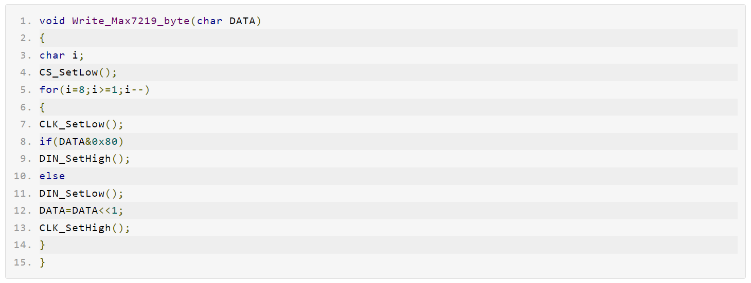 The function for writing data to a register is:
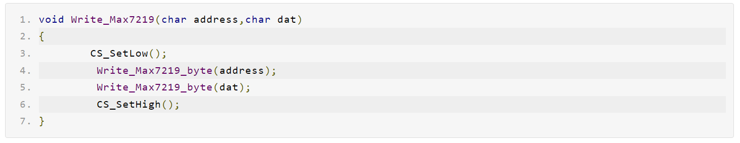 Given that the two modules have different functionalities, their initialization functions and main programs are distinct. Below is a detailed introduction for each.Driving Serial Digit Display Module The serial digit display module is designed to control an 8-digit 7-segment digit tube using the MAX7219 chip. This chip integrates an internal B-type BCD code encoder with a multiplex scanning circuit and segment drivers. Additionally, it includes an 8x8 static RAM for storing display data, as well as an external register to set the segment current for each LED. Each datum can be individually addressed without rewriting when updated, and it also allows users to choose between encoding or not encoding for each datum. During the display process, there is no flickering or jitter, and the module supports cascading for expanding the number of digits displayed. The appearance of the module is shown in Figure 4:

The initialization function for this module is: To achieve the display effect, the main program is as follows:
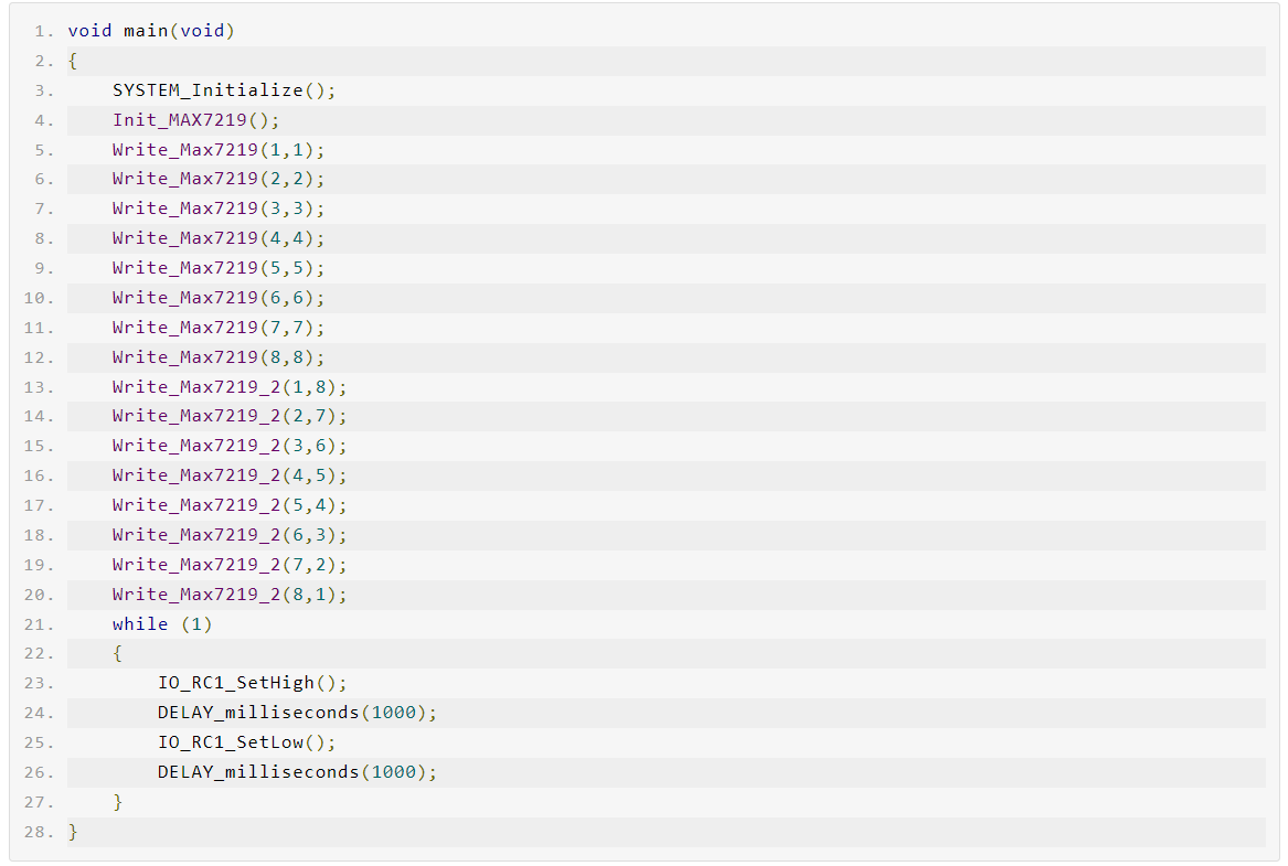 Compared with conventional digital tube displays, this display method features fewer pin resources required and higher brightness, making it suitable for industrial control applications.
2.Driven Matrix Display Module
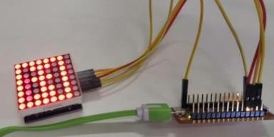
The function of the serial digital tube display module is to control an 88-segment display block using the MAX7219 chip. If a cascading method is adopted, it is possible to drive multiple matrix blocks simultaneously, thus allowing for the simultaneous display of several characters and achieving the output effect of a matrix information screen. The pin arrangement of the 88-segment display block is shown in Figure 1, which is divided into 8 rows and 8 columns. When the corresponding high and low voltages are provided by the row and column lines, respectively, the LED at the intersection of the row and column is lit up. The appearance of this module is depicted in Figure 6, while Figure 7 illustrates its circuit diagram.
 The initialization function for the MAX7219 is:
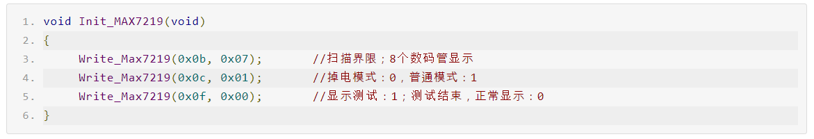 To achieve the display effects, the main program is:
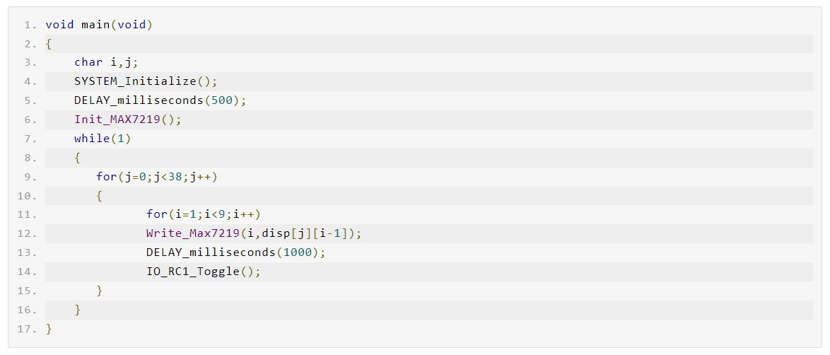 In this context: The inner loop is responsible for displaying a single character, while the outer loop is tasked with iterating through and displaying the content of the character library. During the display process, after each character is shown, the status of the LEDs on the board is toggled once.