Electric Motor PID Experiment
During the study of drones, balance boards, smart cars, and inverted pendulums, we often hear a commonly mentioned term—PID. So what exactly is PID, and what is its purpose? In this article, I have created a basic motor controller to explore the principle of PID and how to use it effectively.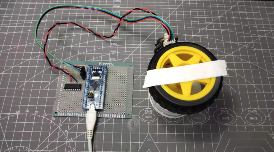
First and foremost, we need to clarify the objectives of the experiment, which are that I should be able to control my motor to rotate through any angle. During the rotation process, the motor must remain stable and not exhibit any oscillations.
Motor Selection
To complete this experiment, the microcontroller needs to control the motor quite precisely and obtain information such as motor speed and position from it. Therefore, a direct current motor with an encoder is required. Through the encoder, the microcontroller can obtain the motor's speed and position information. The encoder motors for sale on the market are generally divided into Hall or optical encoders. Here, I have chosen a TT encoder motor with a reduction ratio of 120 from DFRobot. According to the data manual provided on the official website, his encoder can output 16 pulse signals per revolution. After passing through the gearbox, the output shaft can output a total of 16 * 120 = 1920 pulse signals for one complete rotation.
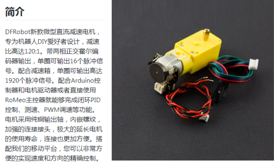 The motor purchased comes with a total of six wires. The four on the left side are for the encoder, while the two on the right side are for the motor itself.
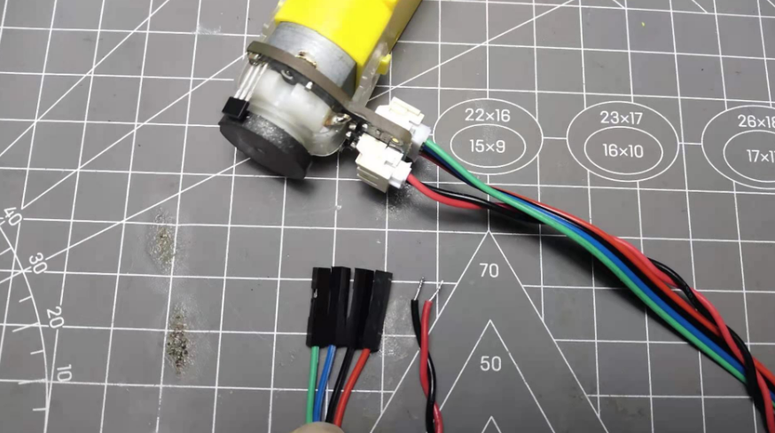
motor driver Chip
For the motor driver chip, I opted for the L293D, which is a dual-channel H-bridge brushed motor driver. With just two input pins and an enable pin, you can control the forward and reverse direction of a motor as well as its speed adjustment.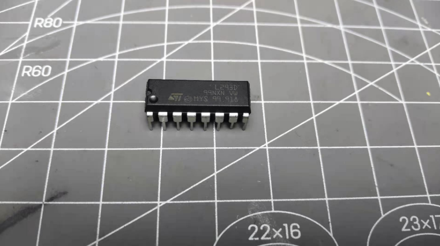
Microcontroller
The microcontroller utilizes the STM32F103C8T6 series core board, which is available for purchase on Taobao. Regarding this specific microcontroller, its timer supports encoder signal input, so all I need to do is connect the motor's encoder output pins to the timer's encoder input pins, thus enabling the timer to automatically count the signals.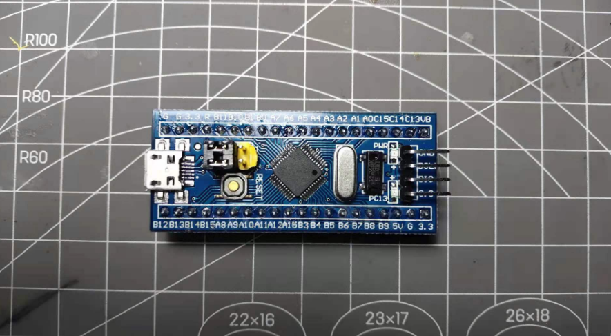 After preparing these materials, I designed a circuit diagram.
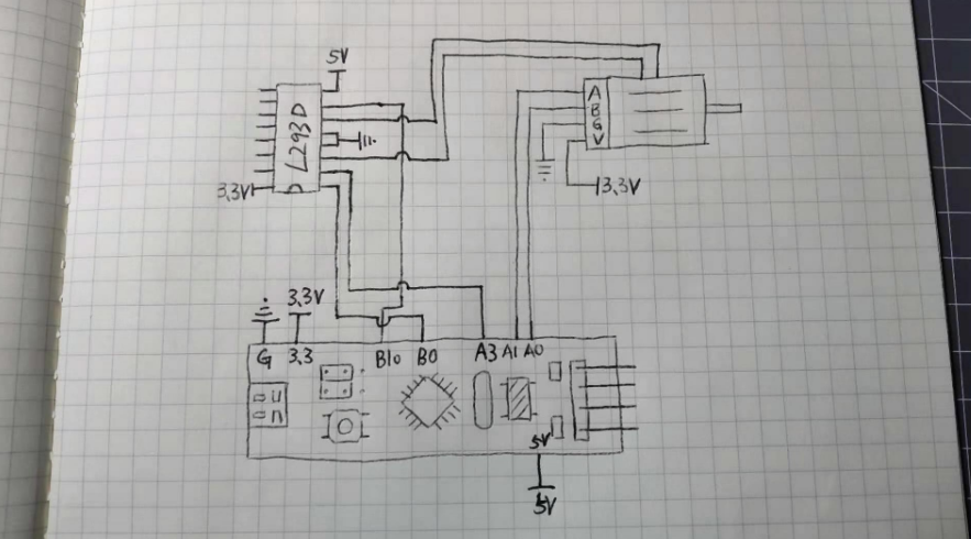 According to this circuit diagram, I have successfully soldered the circuit onto a perforated board.
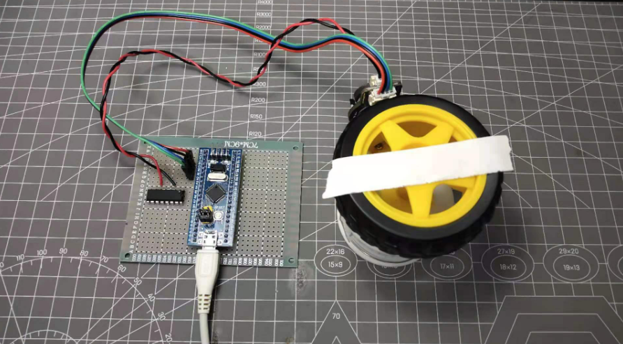 Here, the entire circuit part has been completed. Next up is the software part.
PID Controller
The name of the PID controller actually explains its basic principle. PID stands for three words: Proportion, Integration, and Differential. In Chinese, this translates to Proportional, Integral, and Derivative controllers. As shown in the figure below: Within this setup, the far left side serves as the input for the PID controller, while the far right side is the output of the PID controller. We can observe an arrow pointing from the output back to the sum accumulator on the input side with a negative sign. This signifies that the PID controller operates with negative feedback, and at this point, the error signal is simply the difference between the input signal and the output signal. In layman's terms, using our experimental purpose as an example, when the motor rotates too much, the PID controller will control it to return to the original angle.
After passing through the accumulator, the error signal is divided into three parts: proportional operation, integral operation, and derivative operation. The proportional operation directly multiplies the error signal by the Kp value, in the integral operation, each time the error is integrated and then multiplied by the Ki value, and in the derivative operation, it is the derivative of the error signal multiplied by the Kd value. Kp, Ki, and Kd are all constants, and we need to adjust these three different parameters according to various systems. I will now explain from a mathematical perspective how each operation contributes to the output.
When the error signal is large, the P term actively responds to the output, contributing the largest value, making the P term the main component of the output at this time. When the error signal is rapidly changing, the D term's derivative operation will make a significant contribution to the output. The I term plays a role as a corrector; when there are minor errors accumulated in the system over time, the I term will correct these errors.
Overall, the essence of the PID controller lies in these three operational processes. In this experiment, if I want to control the motor to rotate to a specific angle, my input would be the desired angle of rotation. After processing through the PID controller, it will output a PWM value to control the motor movement, and at the same time, the encoder continuously provides feedback on the current position. Through continuous computation with the PID controller, the motor can quickly and stably rotate to the specified angle.

Implementation of the Code
It is worth noting that for the three operation formulas mentioned in the PID structure diagram above (proportional, derivative, and integral), they all operate on continuous signals. For a microcontroller, it is obviously impossible to handle continuous signals. A feasible approach is to run the PID algorithm at regular intervals. Therefore, for the discrete position PID algorithm, its formula is as follows:![]() For the three variables, their calculation methods are as follows:
For the three variables, their calculation methods are as follows: So, the next step is to implement the entire program. Since the microcontroller board I am using does not have a serial communication chip, it is not conducive to later debugging, so I am using an inherent USB interface of the STM32 to simulate serial port communication. Next, create a new STM32 project and add the related peripheral initialization code (motor encoder, etc.).
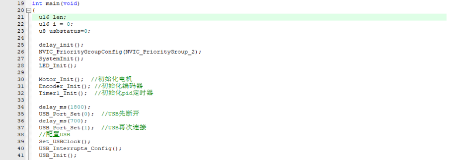 Next, I have written a PID calculation function based on the formula mentioned above.
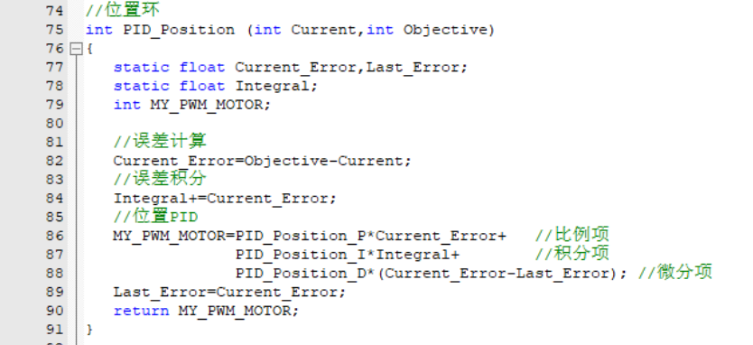 To execute the PID algorithm periodically, I've established a timer with a precision of 5 milliseconds. This allows the PID algorithm to be run each time the timer's interrupt is triggered. From within the interrupt function of the timer, we can observe that the processing entails feeding the current position and the target position into the PID calculator, receiving its output, and then sending it to the motor control function for implementation.
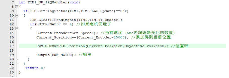 And in the output control function of the motor, the content is as follows:
 Control the rotation direction of the motor through the value output by the PID controller, then limit the range of the PID output values, and finally assign them to the PWM generator.
Experiment
Let us commence with the experiment. Initially, we will set the I and D parameters of the PID controller to zero, while setting a small value for Kp. Subsequently, we compile the project and proceed to flash it onto the STM32. Power up the STM32. If the STM32 uses USB emulated serial port, a software installation is required, which I will include at the end of the document. Open the serial port debugging assistant, type 'h' followed by the Enter key, and click Send; the help information will be printed out. You can see the supported commands, including reading the encoder position, modifying PID parameters, and rotating left and right, etc.
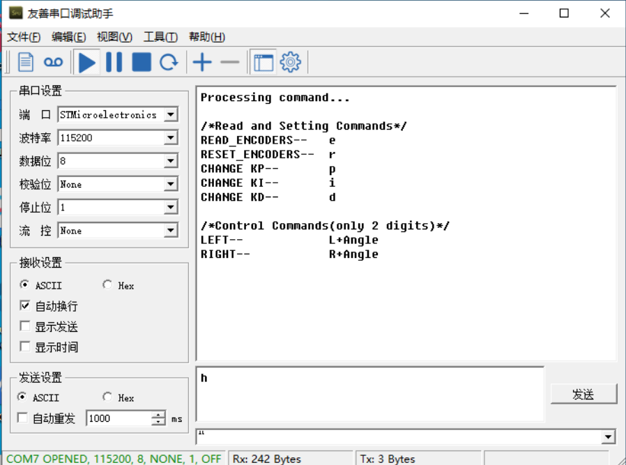 Next, in the serial port debugging assistant, send "L90" followed by Enter and observe the motor rotating by ninety degrees. However, notice that the motor has some wobble and the response speed is relatively slow.
Then, increase the Kp value gradually until the amplitude of the wobble is reduced and the motor's response speed gradually increases. When you notice vibrations near the target position, we start to increase the Kd value to suppress these vibrations. When the Kp value is adjusted to 500 and Kd value to 900, the motor's wobble situation is significantly improved, as shown in the video.
Although the vibration issue is resolved, after several rotations, the motor's error gradually appears, as shown in the figure below; after a full rotation, it cannot return to the original point.
So next, I increased the Ki value, but I would recommend not to increase the Ki value too much, usually within a range of a few tenth of a unit. Here, I set the Ki value to 0.01 to correct the error generated after each rotation.With this, the basic adjustment of PID parameters is almost done, and the motor can execute my instructions very well.
Improvement
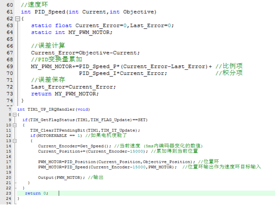
I have found that when the rotation angle is set to a large value, the motor first rotates at full speed and then gradually slows down until it reaches the set position. This brings up a problem: when the motor is running at full speed, the duty cycle of the PWM (Pulse Width Modulation) is 100%, which effectively places the motor directly across the power supply. At this point, we have no control over the motor's speed. Consequently, if there is any instability in the power supply voltage, the motor speed will inevitably fluctuate, leading to unstable rotation. This is certainly not the outcome I desire. Therefore, introducing a speed control loop is necessary in such cases. Due to the inherent inertia that comes with the rotation of an electric motor, its speed cannot undergo abrupt changes. Therefore, I have implemented only a PI control in the velocity loop controller. The velocity loop controller is used to regulate the speed of the motor during its rotation process, and it will be nested within the position loop controller. The final implementation code is as follows.