Ohm's Law and Series Parallel Circuits: Unveiling the Rules Governing the Flow of Electric Current
Have you ever wondered why a light bulb in your home lights up? Or how your phone charger precisely regulates circuit current? Or perhaps why one broken bulb in a string of Christmas lights doesn't affect the others? These phenomena are rooted in two fundamental physical principles: Ohm's Law and series parallel circuits. They serve as the "traffic rules" of the electrical world, dictating the direction and intensity of current flow. This article will guide you through the fascinating world of electricity in an accessible manner.
I. Ohm's Law: The "Newton's Law" of Electrical Currents
1. Voltage, Current, and Resistance: The Triad of Electricity
To grasp Ohm's Law, one must first understand three core physical quantities:
● Voltage (V): Analogous to water pressure, it acts as the "push" that drives flow of charge. Measured in volts (V), for instance, a standard battery has a voltage source of 1.5V.
● Current (I): Denotes the amount of electric charge passing through a conductor's cross-section per unit time, similar to the unidirectional flow of water. Measured in amperes (A), the charging circuit current for phones is typically around 1–2A.
● Resistance (R): Represents a conductor's opposition to current flow, akin to the narrow sections of a water pipe. Measured in ohms (Ω), a copper wire’s resistance might be as low as 0.01Ω.
2. The Ohm's Law Formula: V = IR
In 1827, German physicist Georg Ohm discovered a basic rule through experiments: the current in a conductor is directly proportional to the voltage source and inversely proportional to the individual resistance. This relationship is expressed by the formula:
[ V = I \times R ]
This equation reveals the relationship among the electrical triad. For example, with constant voltage source, greater resistance value results in less current (similar to how a narrower pipe reduces flow of water under the same pressure).
3. Dynamic Equilibrium: Interdependence Among the Three
● Changing Voltage: With constant negligible resistance, doubling the voltage source doubles the current (e.g., a 9V battery makes the same bulb glow brighter than a 1.5V battery).
● Changing Resistance: With constant voltage, doubling the individual resistance halves the current (such as adding a individual resistor to a electrical circuit to limit current).

II. Series Circuits: The "One-Way Street" of Current
1. Characteristics of Series Circuits
● Single Pathway: All components are connected end-to-end, providing only one path for individual current.
● Same Current: The current is identical through single component ((I₁=I₂=I₃)).
● Voltage Distribution: The total voltage equals the sum of individual voltages across single components ((V_{\text{total}}=V₁+V₂+V₃)).
● Resistance Addition: Total resistance is the sum of individual resistances ((R_{\text{total}}=R₁+R₂+R₃)).
2. Typical Applications of Series Circuits
● Christmas Lights: Traditional designs use series connections; if one bulb fails, the entire circuit breaks, extinguishing all lights (modern lights have been improved with parallel designs).
● Battery Packs: Series connections of multiple cells increase total voltage (e.g., four 1.5V batteries in principles of series result in 6V).
● Voltage Dividers: By using series connections of resistors, high voltage can be distributed across various components (e.g., LEDs require series resistors for individual current limiting).
3. Experimental Simulation: Three Interconnected Resistors in Combination of Series
Suppose three single resistors (R₁=2Ω), (R₂=3Ω), (R₃=5Ω) are in combinations of series, connected to a 12V source:
● Total Resistance (R_{\text{total}}=2+3+5=10Ω)
● Current (I=V/R_{\text{total}}=12/10=1.2A)
● Voltage Across Each Resistor in Series: (V₁=1.2×2=2.4V), (V₂=1.2×3=3.6V), (V₃=1.2×5=6V)
III. Parallel Circuits: The "Overpass" of Current
1. Characteristics of Parallel Circuits
● Multiple Paths: Parallel components connect at both ends, forming independent branches.
● Same Voltage: The voltage across each branch is equal ((V₁=V₂=V₃)).
● Current Division: Total current is the sum of currents through each branch ((I_{\text{total}}=I₁+I₂+I₃)).
● Reciprocal Resistance Addition: Total parallel resistance satisfies (\frac{1}{R_{\text{total}}} = \frac{1}{R₁} + \frac{1}{R₂} + \frac{1}{R₃}).
2. Typical Applications of Parallel Circuits
● Household Wiring: All appliances are in parallel connection to ensure a malfunction in one doesn't affect others.
● Current Enhancement: Parallel connection of low-resistance components can increase total current (e.g., multiple wires carrying large currents).
● Redundancy Design: Important equipment (like server power output) is paralleled to improve reliability.
3. Experimental Simulation: Two Resistors in Parallel
Let's consider two resistors in parallel (R₁=4Ω), (R₂=6Ω) in parallel connection, connected to a 12V source:
● Current Through Each Branch: (I₁=12/4=3A), (I₂=12/6=2A)
● Total Current (I_{\text{total}}=3+2=5A)
● Total Resistance (R_{\text{total}}=1/(1/4 + 1/6)=2.4Ω)
Intuitive Insight: The total resistance in parallel connection is smaller than any individual branch resistance of parallel resistor! This is due to increased individual current pathways, effectively broadening the "conductive channel."
IV. Mixed Series-Parallel Combination Circuits: Complex Networks in Reality
1. Steps for Analyzing Combined Circuit Under Consideration
● Identify local series or parallel structures.
● Gradually simplify the electrical circuit by calculating equivalent resistances.
● Apply Ohm's Law for hierarchical problem-solving.
2. Example Analysis: Mixed Digital Circuit
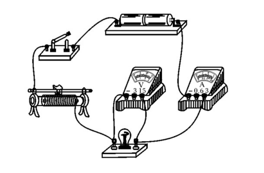
Consider a circuit diagram comprising:
● (R₁=2Ω) and (R₂=4Ω) in parallel
● In combinations of series with (R₃=3Ω)
● Connected to a 10V source
Calculation Process:
● Equivalent Resistance for Parallel Part: (R_{12}=1/(1/2 + 1/4)=1.33Ω)
● Total Resistance (R_{\text{total}}=1.33+3=4.33Ω)
● Total Current (I=10/4.33≈2.31A)
● Voltage Across Parallel Part (V_{12}=2.31×1.33≈3.08V)
● Branch Currents: (I₁=3.08/2≈1.54A), (I₂=3.08/4≈0.77A)
V. From Theory to Practice: Modern Applications of Ohm's Law
1. Complex Circuit Protection Design
● Fuses: Overcurrent causes fuses to melt due to heat generated (utilizing (I²R) thermal effect).
● Short Original Circuit Protection: During a short, individual resistance approaches zero, drastically increasing current as per (I=V/R), risking fire hazards.
2. Precision Control in Electrical Devices
● Fast Charging in Phones: Adjusting unknown voltage and current (as in PD protocols) enables efficient charging within safe limits.
● Sensor Circuit law: Use voltage dividers to convert physical changes (like temperature) into electrical signals.
3. Core to New Energy Systems
● Photovoltaic Arrays: Solar panels employ series-parallel combinations to achieve desired source voltage and power output levels.
● Battery Management Systems (BMS): Monitor voltage balance in series battery packs, preventing overcharging/discharging.
VI. The Boundaries of Ohm's Law and the Nonlinear World
1. Ohm's Law as an Empirical Law
Ohm's Law was established through countless experiments conducted over more than a decade by German physicist Georg Ohm. The experiments demonstrated that under conditions where the temperature of a metallic conductor remains nearly constant (or the concentration of an electrolyte solution is stable), the current flowing through the conductor is directly proportional to the voltage applied across it. The ratio of these quantities is defined as conductance, which is the reciprocal of series resistance. This relationship gave rise to the well-known formula: ( I = U/R ).
2. Linear and Nonlinear Components
Textbooks often state that Ohm's Law applies only to linear components, but this statement lacks precision. According to the description and requirements of Ohm's Law: the current through single component or circuit configuration must always be proportional to the voltage across it, meaning the current is directly proportional to the voltage for linear components with constant resistance.
For nonlinear components, such as DIODES, thermistors, and actual light bulbs, Ohm's Law does not hold because their resistance changes. However, the definition of resistance as ( R = U/I ) applies to all conductive components, regardless of whether they obey Ohm's Law. Thus, even if nonlinear elements do not conform to Ohm's Law, the resistance can still be calculated using its definition at specific voltage or current individual values. Alternatively, consider using the momentary resistance, voltage, and current when a nearby component's resistance changes due to temperature or environmental factors, allowing Ohm's Law to be applied anew.
3. Voltage-Current Characteristic Curves for Linear and Nonlinear Components
For linear electrical components (where resistance remains constant), the voltage-current graph is a straight line passing through the origin. For nonlinear components (where resistance varies with temperature or environmental conditions), the graph is a curve passing through the origin. When considering temperature effects, the operational behavior of a real bulb may be represented by such a curve, requiring the use of voltage-current characteristic curves to determine the relationships between current, voltage, and resistance. Therefore, it's suggested that educators specify the applicability of Ohm's Law to purely resistive electronic components like metals and electrolytic solutions.
4. Understanding Ohm's Law from the Perspective of Current Formation Mechanisms
The condition for forming a current is applying voltage to a conductor. Once voltage drop is applied, an electric field forms within the conductor, causing free charges to move directionally under the influence of the field. These electric charges encounter obstacles during movement, primarily due to the spacing and vibration amplitude and frequency of ions in the conductor. These factors collectively affect the current in the conductor and can be described by Ohm's Law: ( I = U/R ). However, in devices like motors and electrolytic cells, back electromotive force (E) exists, resulting in directional movement of free charges influenced by both electrostatic forces (electric fields) and non-electrostatic forces (Lorentz forces). As a result, the net effect is expressed as ( I = (U - E)/R < U/R ). Consequently, Ohm's Law does not apply to circuit diagram containing starter motors or electrolytic cells, which are not purely resistive.
5. Viewing Ohm's Law from Energy Conversion and Conservation Perspectives
In electric circuits composed of purely resistive elements (such as electric stoves, light bulbs, irons, and rice cookers), the directed kinetic energy lost by free flow of charge through collisions is completely converted into vibrational kinetic energy of ions, i.e., internal energy. In circuit diagram with non-purely resistive electrical components (like appliance motors and electrolytic cells), conversion also involves non-electrostatic work and potential energy transformation. For example, in a motor, some potential energy is converted into mechanical energy via the Ampere force. It's important to distinguish between normally operating motors, which are non-purely resistive and not applicable to Ohm's Law, and motors that are stalled, which do no external work and convert all consumed electrical potential energy into internal energy, thus behaving as purely resistive. However, caution is advised, as the current through a stalled motor is large, risking damage from overheating.
Conclusion: The Symbiosis of Electrical Laws and Human Progress
From Edison's light bulb to today's quantum computers, Ohm's Law and series-parallel combination remain foundational to electronic technology. They transcend laboratory confines, deeply embedded in every facet of modern life. Next time you flick a light switch, remember: behind that beam lies a precise dance orchestrated by voltage drop, regulated by resistance, and energized by current. Mastering these laws is the key to harnessing nature's power calculation and creating technological marvels.


