Master the STM32 to create a sophisticated heart rate monitor
This design is based on a low-cost, high-precision method centered around the STM32F103ZET6. It employs a pulse sensor to detect and collect the human pulse. Using the microcontroller's timer/counter, it measures the heart rate, with digital display and voice broadcast controlled by the microcontroller. This ensures quick and accurate heart rate measurements. Additionally, when an abnormal heart rate is detected, the DS18B20 alarm module alerts the user to pay attention to heart rate monitoring.
Chapter 1: Introduction
Heart rate refers to the number of times the heart beats per minute. It is an important parameter reflecting whether the heart is functioning normally, and the value of the heart rate is also a crucial indicator for assessing both physical labor intensity and mental work intensity. Therefore, measuring heart rate is an excellent method for evaluating a patient's physiological status.A heart rate monitor is a medical device used to measure heart rate values. Its application plays a significant role in the research and diagnosis of cardiovascular diseases, as the bioelectrical signals it records during cardiac activity have become vital for clinical diagnosis. With the continuous development and progress of modern medicine, the demands on various measurement instruments are naturally increasing. Based on previous research, we have developed and designed a cost-effective electronic heart rate monitor. This device addresses the inaccuracies and randomness of traditional measurement methods, providing precise heart rate measurements and displaying the results digitally in real-time, thus making heart rate values more intuitive.
Chapter 2: Design Plan
The basic principle of photoplethysmography (PPG) is to measure pulse rate using the variation in light transmission caused by blood vessel pulsation. The sensor used consists of two parts: a light source and a photoelectric transducer, which can be attached to a patient's finger or earlobe using a strap or clip. The light source typically uses light-emitting DIODES (LEDs) with specific wavelengths (500nm~700nm) that selectively target arterial oxygen and hemoglobin. When the light beam passes through peripheral blood vessels, the transmission rate changes due to volumetric changes caused by arterial pulsations. The photoelectric converter then receives the light reflected by the body tissues, converting it into electrical signals, amplifying and outputting them. Since the pulse rate is a periodically changing signal corresponding to the heartbeat, with periodic changes in arterial blood volume, the period of change in the electrical signal from the photoelectric converter represents the pulse rate.
Chapter 3: Overview of Hardware Circuit
3.1 Principles of Heart Rate Monitor DesignAccording to design requirements, this design employs the STM32F103ZET6 as the control CPU, with peripheral devices including the digital temperature sensor DS18820, phototransistors, a voice module, decoders, latches, amplifiers, etc. The project adopts a bus control mode, with three-digit static digital display.3.2 Pulse Sensor PrincipleThe PulseSensor is a photoplethysmographic analog sensor used for heart rate measurement. Worn on the finger or earlobe, it transmits collected analog signals via wires to the STM32F103ZET6 microcontroller, where they are converted into digital signals. Simple calculations by the STM32 yield the heart rate value, and the pulse waveform can also be transmitted to a computer via a serial port for display.Due to the extremely weak pulse signal and its limited vibration amplitude, collecting and obtaining the signal can be quite challenging. Not only is the pulse signal itself weak, but it is also prone to interference, as physiological signals from different parts of the body interact and influence each other. Furthermore, emotional variations such as joy, anger, sorrow, and happiness can also affect physiological signals, leading to noise interference in the pulse signal. Therefore, selecting an appropriate pulse measurement sensor is crucial for obtaining accurate, efficient, and reliable pulse signals. The frequency of the pulse signal is very low, with typical values as follows: males have 60-100 beats per minute, females 70-90 beats per minute, and children around 90 beats per minute.Pin functions are as follows:S — Pulse signal output (connected to microcontroller AD interface)VCC — 5V (or 3.3V) power inputGND — Ground3.3 ISD1820 Voice ModulePin function introduction:Power (VCC): Convergence point for different internal power buses of the chip's analog and digital circuits, minimizing noise. Decoupling capacitors should be placed close to the chip.Ground (VSSA, VSSD): Convergence point for different ground lines of the chip's internal analog and digital circuits.Record (REC): Active high; recording starts when REC goes high, regardless of whether the chip is in power-saving mode or playback mode. Recording continues while REC is high and stops when REC goes low or the memory is full, writing an End-of-Message (EOM) mark.Edge Trigger Playback (PLAYE): Playback starts on rising edge, continues until EOM mark or end of memory, and then enters power-saving mode.Level Trigger Playback (PLAYL): Playback starts when this pin goes high and continues until it returns to low, encounters an EOM mark, or reaches the end of memory, entering power-saving mode afterward.Recording Indicator (/RECLED): Low during recording, can drive an LED; outputs a low pulse upon encountering an EOM mark during playback, useful for triggering PLAYE for looping playback.Microphone Input (MIC): Connects to the internal pre-amplifier. External microphone should be coupled via a series capacitor.Microphone Reference (MIC REF): Inverting input of the pre-amplifier, improving common-mode rejection ratio when connected differentially.Speaker Output (SP+, SP-): Directly drives an 8Ω speaker; dual-ended output increases power by four times without coupling capacitors.Oscillation Resistor (ROSC): Connected oscillation resistor determines recording and playback time.Pass-through Mode (FT): Allows external audio signals at MIC input to pass through internal AGC circuit, filter, and speaker driver to reach speaker output directly when FT is high and REC, PLAYE, and PLAYL are low.
Chapter 4: Program Design
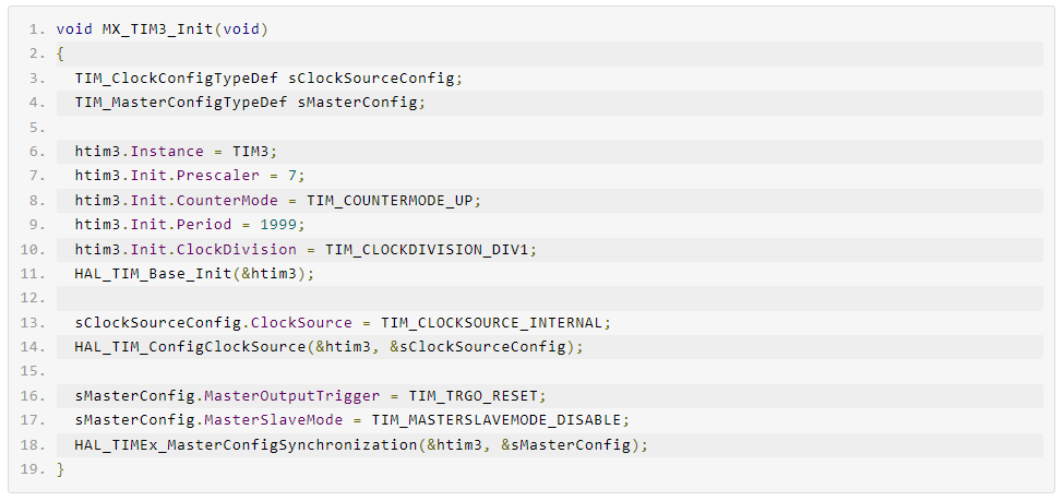
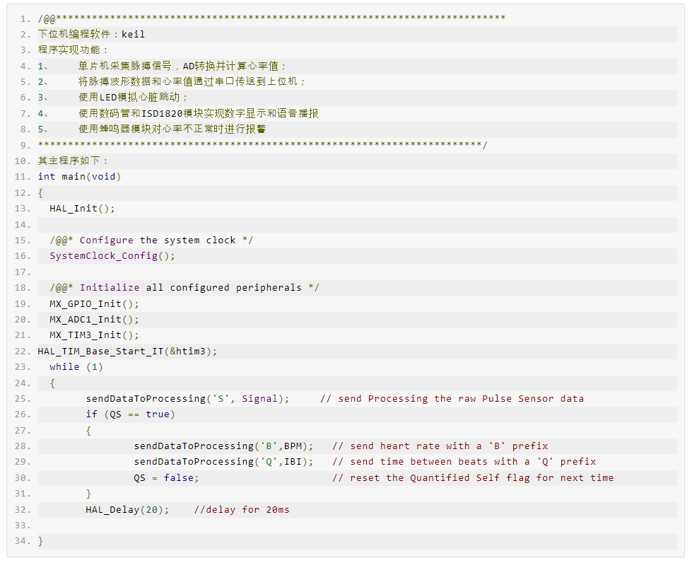
4.1 Main Program DesignProgram functionalities: By detecting high or low levels at port P1.0, the program can collect, convert, and process temperature data and electrocardiogram signals, finally displaying heart rate and temperature values on a digital tube. Additionally, the speech subroutine can announce these values, and an alert module can notify the user if the heart rate falls outside the set range, prompting attention to physical health.Designing the main program flowchart is a crucial step, representing our design concept concretely. With the flowchart, we can break down a complex software design into several functional modules and design each module individually.In the main program design, we first initialize components, including the display module. Then, we determine whether P1.1 is high or low to decide whether to measure body temperature or heart rate.4.1.1 Flowchart of the Main Program
4.1.2 Overview of the ISD1820 Voice Module FunctionsThe ISD1820 module primarily offers three functions: recording, level-controlled playback, and pulse-triggered playback.Recording SubroutineControlling the recording process involves two main parameters: 1) the starting address for recording, and 2) the duration of the recording. By managing these two parameters, you can determine which segments the audio will be recorded into. Note: The REC signal is delayed by 50ms to prevent debounce and avoid repeated triggering. When invoking the recording subroutine, simply provide the starting address and the desired recording duration.Level-Controlled Playback SubroutineFor level-controlled playback, both the starting address and playback time are essential. Controlling these two parameters will define the content being played back. It is important to note that playback always commences from the beginning of a segment. For segmented playback control, each recording's start must align with the beginning of a segment. To invoke the level-controlled playback subroutine, just provide the playback starting address and duration.Pulse-Triggered Playback SubroutinePulse-triggered playback differs slightly from level-controlled playback. Here, the playback duration cannot be controlled via a microcontroller; only the starting address can be managed. Once initiated, pulse-triggered playback continues until either an end marker or the chip's memory limit is reached. Therefore, it is less commonly used for segmented voice control. To call the pulse-triggered playback subroutine, simply supply the starting address.4.2 Heart Rate Measurement Program Design4.2.1 Program Design for Heart Rate MeasurementThe heart rate measurement program consists of two parts. The first part involves initialization, including setting up timers/counters, configuring stack pointers, and enabling interrupts. The second part activates two timers/counters and invokes display and voice broadcast subroutines to complete the heart rate display, voice announcement, and alarm module functionalities.4.2.2 Interrupt Service Routine Design