Current Across a Capacitor: What You Must Know
Introduction of Capacitor
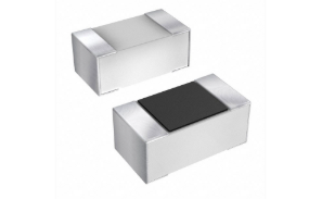
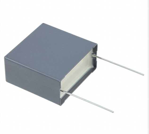
Capacitor is a passive electronic component that stores electrical energy in an electric field. Currently, it is widely used in every aspect of our lives, from small chargers to large power grid systems, without the support of capacitors. As we recognize in the study of basic physics, the capacitor is one of the most basic and versatile components in electrical engineering, consisting of two conductive plates separated by an insulating material. It consists of two conducting plates separated by an insulating material. It works by applying a voltage to form an electric field to gather positive and negative charges.
Capacitor plays a great role in our daily life with its unique performance, its working principle and structure sounds simple, but actually the structure is very delicate.
Series vs. Parallel Capacitor Configurations
Series Connection Properties Series circuits are an important part of basic physics and we know a lot about them. When capacitors are connected in series, they form a chain where the same electric current flows through each element in turn. This configuration has a couple of unique properties that are worth noting: first, in a series arrangement, the total capacitance decreases rather than increases, which is often counterintuitive to the electronics novice. This is because the effective distance between the poles increases
while the total electric charge storage capacity decreases.
We can verify this feature by looking at the series capacitance equation: The total capacitance of a series configuration is calculated as:
1/C_total = 1/C₁ + 1/C₂ + 1/C₃ + ... + 1/C_n
This inverse relationship means that the total capacitance is always less than the smallest individual capacitance in the series connection. For example, if two 10μF capacitors are connected in series, the total capacitance will become 5μF instead of the 20μF originally assumed.
Another important feature is the voltage distribution across each component. The voltage distribution is inversely proportional to the capacitance value, which means that the smaller capacitor has a larger voltage drop. This characteristic is especially important in high voltage applications where series connections are used to distribute the initial voltage across multiple capacitors, preventing any individual element from exceeding its voltage rating.
This principle is also widely used in our life, the most intuitive example is with the production of new energy vehicles and the construction of electric vehicle fast charging piles, 350kW DC fast charging piles of input filtering is precisely the use of multi-layer series structure: the first level of 20 400V film capacitors connected in series to withstand the 8kV grid transient, the second level of the change to the combination of SiC devices and series capacitors, thus realizing more than 97% of the energy conversion efficiency, to achieve the “energy conversion efficiency,” to achieve a “high” voltage. Energy conversion efficiency, to achieve the purpose of “fast charging”.

Parallel Connection Characteristics
Parallel capacitor configurations have significantly different characteristics compared to series capacitor configurations. Capacitors in parallel have a relatively more complex configuration, sharing connection points at both ends without voltage difference on each element. And this configuration effectively increases the total plate area available for charge storage, thus creating a stacking effect on the total capacitance.
Again, we can use the formula for parallel total capacitance to help us understand this property: C_total = C₁ + C₂ + C₃ + ... + C_n In this case, connecting two 10μF capacitors in parallel results in a total capacitance of 20μF.
This additive property makes the parallel configuration ideally suited for applications requiring large capacitance values,such as practical capacitors that require large amounts of energy storage to smooth out voltage fluctuations,a principle which is nowadays widely used in industry, such as the DC bus support of new energy inverters, and which has greatly advanced the progress and development of modern industry.
The current distribution in a shunt capacitor is related to the capacitance value, with larger capacitors drawing more current during the charging and discharging cycles. This characteristic must be taken into account in high-current applications to ensure proper current sharing and prevent overloading of individual components. The most common application of this principle in life is the DC bus support capacitor bank of an 800V high voltage fast charging pile. Compared to a 350V charging pile using a series capacitor bank, the 800V charging pile has to deal with instantaneous current fluctuations in the hundreds of amperes, so its main and auxiliary capacitors are connected in parallel.
Capacitance in Series vs. Parallel: Practical Implications
Energy Storage Considerations
The difference in capacitance between series and parallel configurations has a significant impact on energy storage capacity. Since the energy stored in a capacitor is given by E = ½CV², a parallel configuration has a larger capacitance and can store significantly more energy at a given voltage than a series configuration. This is why large capacitor banks in power systems and energy storage applications are often connected in parallel configuration.
However, in high-voltage applications where individual capacitors are not rated for sufficient voltage, series configurations have their advantages. By connecting capacitors in series, engineers can create systems that can withstand higher voltages while keeping the ratings of individual components within manageable limits. Surveys have shown that in practice this approach is commonly used in pulsed power systems, high-voltage power supplies and certain types of power factor correction circuits.
Frequency Response Differences
The configuration of a capacitor also affects its frequency response characteristics. In a series configuration, a decrease in total capacitance results in a higher impedance at a given frequency (since X_C = 1/(2πfC)). This characteristic is often utilized in parasitic capacitance, where series capacitors are used to block DC while allowing AC signals to pass through. The cutoff frequency of such circuits is directly dependent on the total series capacitance and resistance in the circuit.
Parallel configurations with increased total capacitance exhibit lower impedance at any given frequency. This makes them mostly used as bypass capacitors in power distribution systems where low impedance is needed to effectively shunt high frequency noise to ground. Parallel combinations of multiple capacitors of different values are often used to produce a broadband filtering effect, where smaller capacitors are used for high frequencies and larger capacitors are used for low frequencies.
Such a combination can be found everywhere in our lives, such as some years ago, the rumor of a “table lamp to buy expensive to not hurt your eyes”, this sentence is not empty. High-quality table lamp manufacturing process is to follow the principle described above, with a larger 33μF electrolytic capacitance to eliminate 100Hz frequency flicker, with a smaller 4.7nF film capacitance to inhibit PWM dimming generated by more than 10kHz high-frequency oscillations, the depth of the strobe from 30% to 5%, so as to do not hurt the eyes.

Voltage-Current Relationship in Capacitors
Fundamental Differential Relationship
The defining characteristic of a capacitor is its unique voltage-current relationship, which we can understand here with the aid of the equation: i(t) = C(dv/dt)
This simple but profound equation shows that the current through a capacitor at any instant is proportional to the rate of change of voltage across the capacitor. This constant of proportionality is the capacitance value C. This relationship has several important implications that set capacitors apart from other circuit components.
First, it explains why a capacitor shows up as an open circuit at a steady DC voltage-when the voltage does not change (dv/dt = 0), no current flows. Second, it reveals why capacitors pass AC signals more easily at higher frequencies - the faster the voltage changes (the higher the dv/dt), the more current flows. This frequency-dependent behavior is what makes capacitors so valuable in filtering and signal processing applications.
Time Domain Behavior: Charging and Discharging
When examining capacitors in the time domain, we observe characteristic exponential curves during charging and discharging cycles. For a capacitor charging through a resistor in a simple RC circuit, the voltage across the capacitor follows:
v(t) = V₀(1 - e^(-t/RC))
Where V₀ is the source voltage, R is the resistance, and C is the capacitance. The product RC is known as the time constant (τ), representing the time required for the voltage to reach approximately 63.2% of its final value.
During discharge, the voltage follows a complementary exponential decay:
v(t) = V₀e^(-t/RC)
Here, the time constant represents the time for the voltage to decay to about 36.8% of its initial value. These equations are fundamental to understanding timing circuits, pulse shaping, and many other capacitor applications.
AC vs DC current
Electrical energy flows in two basic forms: AC and DC.

DC flows in a constant unidirectional direction and has a stable voltage, making it ideal for electronic devices and battery-powered systems, and most modern electronics rely on DC to maintain essential site functionality, such as our cell phones and computers. However, DC power faces limitations in long distance transmission due to significant energy losses.
AC, which flows periodically in the reverse direction, dominates our power grids because it can be efficiently converted to different voltages. This property minimizes energy loss in long distance transmission of high voltage, which is then safely stepped down for home use. We typically use 50Hz or 60Hz AC in our homes to power all of our devices.
Although AC has won the “war of currents” throughout history, both forms still play their respective roles today and together they build our lives.
Phase Difference in AC Circuits
In AC circuits, the voltage-current relationship in capacitors leads to a 90-degree phase shift, with flow of current leading voltage. This phase relationship is crucial for understanding power factor in AC systems and forms the basis for many signal processing techniques. Capacitive reactance (X_C = 1/(2πfC)) quantifies the impedance of a capacitor to AC currents, with higher frequency AC currents being accompanied by lower capacitive reactance.
Current Flow Mechanisms in Capacitors
Relationship Between Capacitors and Electric Fields
To understand how the current in a capacitor works, we must introduce a new concept, the electrical field, which is the physical basis for the operation of a capacitor.
A capacitor stores energy in the electrical field formed between its conducting plates. When a voltage is applied, an opposite charge accumulates on each pole plate, thus creating an electrical field on the dielectric (E=V/d). The strength of the electrical field directly determines the capacitor's ability to store energy (W=½CV²=½εE²Ad).
For the definition of the electrical field, modern physics generally uses the formula for the Gaussian surface in Maxwell's system of equations.
Physical Interpretation of Current Flow
As presented at the beginning of this article, it is important to understand that, in the traditional sense, current does not actually flow through the electronic circuits of a capacitor; the current we observe in a capacitor is the movement of both positive charges and negative charges across the capacitor plates as the voltage changes. When the voltage is increased, electrons will accumulate on one positive plate and deplete on the negative plate, which creates the appearance of current flowing through the external circuit.
This displacement current we call capacitor current. The electric field between the pole plates changes as charge accumulates, and this changing electric field is the underlying cause of what we observe when we measure capacitor current. Maxwell's equations formalize the relationship between the changing electric field and the displacement current.
Initial Current Surge and Steady-State Behavior
We assume that if a voltage is applied to the capacitor without current source, then a large initial current surge will usually occur.This leads to a potential difference between the current and voltage, where the current lags behind the voltage.This is because at t=0, the capacitor voltage is zero and forms a short circuit with the voltage source. The initial current is limited only by the resistance in the circuit (including the internal resistance of the voltage source) and can be quite substantial in low resistance circuits.
As the capacitor charges, the current will decrease exponentially with the following equation: i(t) = (V₀/R)e^(-t/RC).
Eventually, when fully charged to the source voltage, the current stops completely in the DC circuit. This behavior explains why capacitors are effective in blocking DC while passing AC signals.
Ripple Current Considerations
In power supply applications, capacitors experience what's called ripple current - the AC component of current resulting from charging and discharging cycles. This ripple current generates heat within the capacitor due to its equivalent series resistance (ESR), and excessive ripple current can lead to premature capacitor failure. Proper capacitor selection must consider both the RMS value of expected ripple current and the component's ability to handle it without excessive temperature rise.
Advanced Considerations and Practical Applications of Capacitors
Equivalent Circuit Models
It is worth noting that the behavior of actual capacitors is more complex than the ideal model suggests. A more accurate model includes equivalent series resistance (ESR), equivalent series inductance (ESL), and leakage resistance. These parasitic elements affect high-frequency performance, power dissipation, and overall capacitor behavior in practical circuits.
At very high frequencies, the ESL can dominate the impedance, causing what should be a bypass capacitor to actually behave like an inductor. This is why careful capacitor selection and placement is critical in high-speed digital circuits and RF applications.
Temperature and Aging Effects
Temperature and aging effects I believe we have all experienced the failure of electronic products due to ageing problems, such as bulging computer motherboards, AC noise in stereos, and even spontaneous combustion of rechargeable batteries, and what is the reason behind this? In fact, it is the characteristics of capacitors are affected by temperature and aging and change. Especially electrolytic capacitors, with aging, their ESR will increase, capacitance will decrease or even fail, seriously affecting circuit performance, especially in timing applications or power filters where capacitance values must be consistent.
Capacitors are inevitably affected by these factors, so how to maximize their service life over a wide temperature range has become a problem for the modern electronics industry.
Safety Considerations
Capacitors can store dangerous amounts of energy even when disconnected from power sources. Large capacitors in power supplies, for example, can maintain lethal voltages long after power is removed.I believe we have all heard of related accidents at one time or another in our lives, such as the instantaneous release of current from an undischarged high-voltage capacitor(≥1kv) during the repair of an old television set or air conditioner, resulting in electrocution. That's why proper discharge mechanisms and safety protocols are essential when working with high-capacitance or high-voltage capacitors.
Additionally, certain capacitor types (particularly electrolytics) can fail catastrophically if subjected to voltages beyond their ratings or if installed with incorrect polarity. Understanding these limitations, when there is a need to install capacitors, it is important not only to choose high-quality capacitors, but also to hire professional engineers to design and install them, and to rigorously carry out troubleshooting activities
Conclusion: Mastering Capacitor Current for Better Design
Modern studies of currents in capacitors have shown that these elements are dynamic, time-varying components that interact with voltage in complex ways. From the basic voltage-current relationship to their behavior in various configurations, capacitors are powerful tools for shaping electrical signals and managing energy flow.
Understanding these principles leads to better circuit design, more efficient troubleshooting, and more innovative solutions to engineering challenges. Whether you're dealing with simple RC timing circuits or complex power distribution systems, a deep understanding of the current behavior of capacitors is an essential part of the electrical engineer's toolkit.
In the previous article, we listed a few common physics formulas to help you understand the principles of capacitors. Admittedly, formulas are an integral part of the study of physics, but in addition to memorizing formulas by rote, engineers can use their physical intuition to understand the workings of capacitors to create more reliable, efficient, and effective electronic systems.From the first invention of capacitor by Pieter Van Musschenbroek in the 19th century to the present diverse types of capacitor, from traditional power electronic equipment to cutting-edge renewable energy systems, the unique characteristics of capacitors have made them more and more widely used in human life, and become an indispensable part of the development of human society.


