
A Guide to Circuit Symbols of Electronic Components: Understanding Made Easy!
Circuit diagrams are a graphical representation of electronic circuits, using standardized symbols to depict the electrical components and their relationships. Widely used in engineering and circuit research, these diagrams allow us to understand the working principles of electronic components and provide planning solutions for performance and installation. Knowing the circuit symbols of electronic components is essential for drawing an effective circuit diagram. These electronic symbols can be categorized into four main types: transmission paths, integrated circuit components, limiting electronic symbols, and switch symbol & relay symbols. Comprehensive knowledge of these electronic symbols enables users to efficiently complete tasks.

Common Symbols of Electric Components
Resistors
● Standard Resistor: Denoted by "R".
● Potentiometer: Denoted by "RP", with "P" indicating its adjustable nature.
Special Types:
1.Thermistor: Resistance varies with temperature. Negative Temperature Coefficient (NTC) or Positive Temperature Coefficient (PTC) thermistors are denoted by "RT".
2.Photoresistor: Depicted with slanted arrows indicating light, symbolized as "RL".
3.Varistor: Resistance changes with applied voltage, represented by "RV".
4.Fuse Resistor: Combines resistor and fuse functions, symbolized as "RF".
Capacitors
● Fixed Capacitor: Symbolized as "(a)".
● Polarized Capacitor: Often electrolytic, represented as "(b)".
● Variable Capacitor: Denoted as "(c)".
● trimmer capacitor: Indicated as "(d)".
● Dual-gang Variable Capacitor: Shown as "(e)".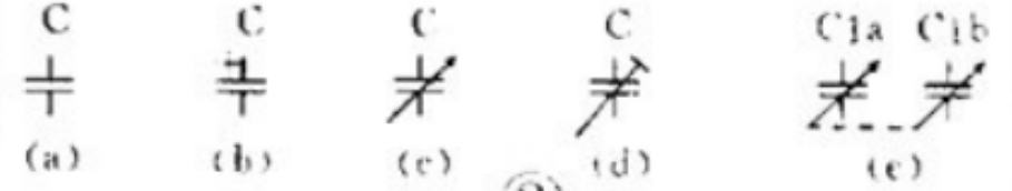
Inductors
● General Inductor: Denoted by "(a)".
● Inductor with Core: Represented as "(b)".
● Gapped Core Inductor: Denoted by "(c)".
● Adjustable Inductor: Shown as "(d)".
● Tapped Inductor: Indicated as "(e)".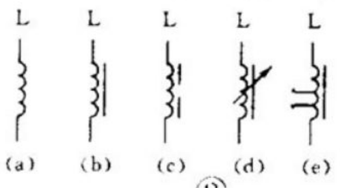
Connection Elements
In electronic circuits, connection elements are often required to establish, interrupt, or switch pathways within the circuit. These connection elements fall into two main categories: switches and connectors.
Switches
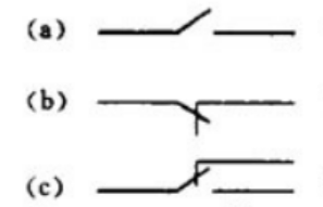
Switches are essential components used to control the flow of electricity by opening or closing circuits. In electromechanical switches, there is at least one movable contact (often referred to as the "moving" contact) and one stationary contact. By manually toggling, pushing, or rotating the switch mechanism, the moving contact can be made to connect with or disconnect from the stationary contact, thereby completing or breaking the circuit. There are three primary configurations for these contacts:
1.Normally Open Contact (NO):
Symbolized as (a), this type of contact remains open in its default state and closes when the switch symbol is activated, allowing current source to flow.
2.Normally Closed Contact (NC):
Represented by (b), this contact is closed in its default state and opens upon activation, stopping the current flow.
3.Changeover Contact:
Shown as (c), this configuration allows switching between two different digital circuits, effectively changing the flow path as needed.
Simple switches may contain a single set of contacts, while more complex switches can have multiple sets, each capable of controlling different parts of a digital circuit or separate electric circuits altogether. Understanding their logical operation and configuration is crucial for designing electric circuits that require precise control over connectivity and functionality.
The alphanumeric symbol for switches is "S." For specific types of switches, additional letters are used:
● Control Switches: Denoted as "SA," these are used for general control purposes.
● Push-Button Switches: Represented by "SB," these are typically momentary switches that maintain contact while pressed.
Connectors
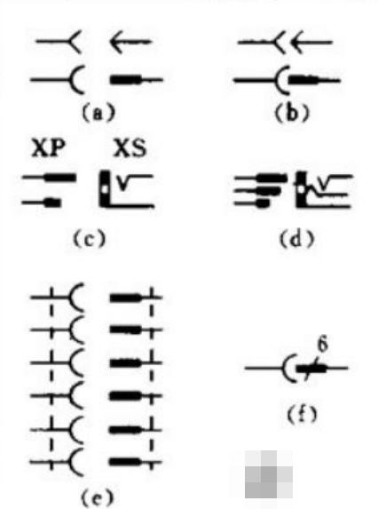
Connectors are indicated by the electronic symbol "X." To differentiate between parts of the connector:
● Plug (XP): Represents the male part of a connector electrical system.
● Socket (XS): Represents the female part, designed to receive the plug.
Various configurations of plugs and sockets include:
1.Single Plug and Socket:
(a) Illustrates two methods to electronic component symbolize a pair consisting of one plug and one socket, with the socket on the left and the plug on the right.
2.Plug Inserted into Socket:
(b) Depicts a configuration where the plug is shown inserted into the socket, forming a complete connection.
3.Two-Pin Connector:
(c) Also known as a 2-core connector, this variant features two terminals, commonly used for straightforward electrical connections.
4.Three-Pin Connector:
(d) Often utilized in three-core stereo headphone jacks, this configuration provides connections for left audio, right audio, and ground.
5.Six-Pin Connector:
(e) This version represents a six-terminal configuration, offering expanded connectivity options, usually found in more complex audio or data interfaces.
By understanding these electrical symbols and their applications, you can effectively work with and design complex circuit electronic systems that incorporate various switching and connecting functionalities.
Relays
Relays are crucial components in electrical circuits, serving as electrically operated switches. They consist of two main parts: the coil and the contact set. In circuit diagrams, the schematic symbol for a relay typically includes both these elements:
● Coil: Represented by a rectangle, it energizes to create a magnetic field that activates the contacts.
● Contacts: These are depicted using contact electrical symbols and represent the switching mechanism.
Electronic Component Symbol Representation:
1.Concentrated Representation:
When the relay has few contacts and the circuit is relatively simple, the contact set is often drawn directly next to the coil. This method simplifies the visualization when all components are closely related.
2.Distributed Representation:
For relays with many contacts or when each contact controls a different part of the circuit, it's more practical to use a distributed graphical representation. Here, the coil is drawn within the control circuit while the contacts are placed within their respective controlled circuits. This arrangement facilitates circuit simplification and analysis. Each contact must be annotated with the relay’s identifier and the specific contact number. Additionally, all contacts are shown in their de-energized (original) state for clarity and consistency.
Relay Symbol Notation:
● General Relay Symbol: "K"
● AC Relay: Sometimes denoted as "KA" to distinguish from other types.
● Electromagnetic and Reed Relays: May be referred to as "KR."
● Time-Delay Relay: Identified with "KT."
DIODES and Transistors
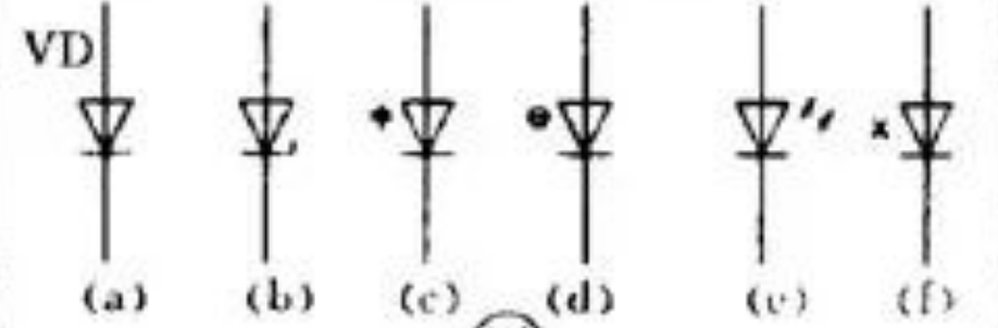
In circuit diagrams, diodes are represented by specific symbols, with the letter "V" often used as their alphanumeric designation. To distinguish them from transistors, "VD" is sometimes employed. Here’s a breakdown of various diode types and their symbols:
1.Standard Diode:
(a) illustrates a standard diode, where the arrow indicates the direction of conventional current flow. This means the diode conducts when a positive voltage is applied to its anode and a negative voltage to its cathode.
2.Zener Diode:
(b) represents a Zener diode, known for its ability to allow current source to flow in the reverse direction when a specific breakdown voltage is reached, making it useful for voltage regulation.
3.Varactor Diode:
(c) depicts a varactor or varicap diode, which includes an adjacent capacitor symbol indicating that its junction capacitance varies with the voltage across its terminals, commonly used in tuning circuits.
4.Thermal Diode:
(d) is used for a thermal diode, which is sensitive to temperature changes and can be used for temperature sensing applications.
5.Light Emitting Diode (LED):
(e) portrays an LED, characterized by two outward-pointing arrows, signifying its ability to emit light when forward biased.
6.Magnetic Sensitive Diode:
(f) signifies a magnetic sensitive diode, which responds to external magnetic fields and is often used in proximity switches and automatic control digital systems.
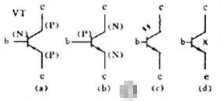
In the realm of transistors, distinguishing between PNP and NPN types is crucial due to their differing requirements for power supply polarity. Their graphical symbols reflect these differences, providing clarity in circuit design and implementation. Here’s how various types are represented:
(a) is used universally for PNP transistors, regardless of whether they are made from germanium or silicon material. The electronic component symbol features an arrow on the emitter pointing inward, indicating flow of current into the transistor. NPN Transistor:
(b) represents NPN transistors, again irrespective of the core material used (germanium or silicon). The emitter's arrow points outward, signifying flow of current out of the transistor. Photosensitive Transistor:
(c) depicts a photosensitive or phototransistor, which includes additional lines or arrows pointing towards the base, representing its sensitivity to light for activation. Silicon NPN Magnetic Sensitive Transistor:
(d) indicates a silicon-based NPN magnetic sensitive transistor, designed to respond to external magnetic fields, often utilized in applications requiring magnetic field detection or response.
Thyristors and field-effect transistors (FETs)
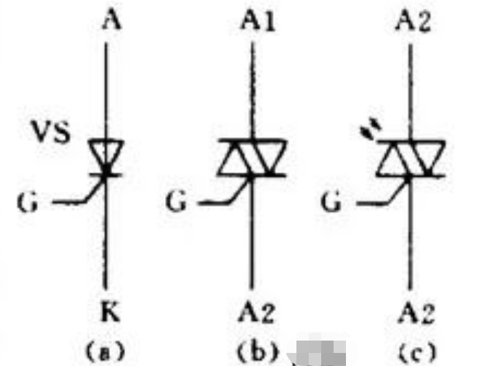
Thyristors, commonly referred to as silicon-controlled rectifiers (SCRs) or simply by the notation "VS" in schematic diagrams, are key components in power control applications. Let's explore the typical types of thyristors and their symbols:
Unidirectional Thyristor (Standard SCR):This type allows electric current to flow in a single direction once it is triggered via its gate terminal. The electronic component symbol features an arrow pointing in the direction of conventional current flow, similar to a diode, but with an added basic gate line.
Bidirectional Thyristor (Triac):Also known as a Triac, this electrical device can conduct electric current in both directions when appropriately triggered. Its symbol includes two back-to-back diodes with a shared gate terminal, indicating its capability to control AC electrical currents across both phases of the cycle.
Light-Activated Thyristor (LASCR):This variant incorporates a light-sensitive triggering mechanism. The standardized symbol is akin to that of an international standard SCR but includes arrows pointing towards the gate, denoting its photo-sensitive nature.
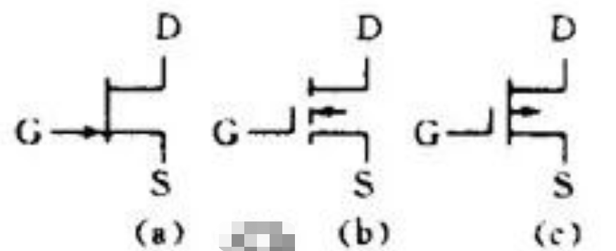
Field-effect transistors (FETs) are semiconductor devices controlled by electric fields. They come in various configurations, each with unique characteristics and standard symbols. In circuit diagrams, they are often denoted as "VT." Here’s an overview of some common types of FETs and their symbols:
N-Channel Junction FET (jfet):(a) represents an N-channel JFET. It includes three terminals: the gate (G), source (S), and drain (D). The arrow on the standard symbol points inward towards the gate region, indicating the direction of conventional current flow from source to drain.
N-Channel Enhancement-type Insulated Gate FET (mosfet):(b) depicts an N-channel enhancement-mode MOSFET. This type of FET requires a positive voltage at the gate relative to the source to conduct. Its symbol includes an insulated gate line that does not touch the channel, signifying the need for enhancement to allow current flow.
P-Channel Depletion-type Insulated Gate FET (MOSFET): (c) illustrates a P-channel depletion-mode MOSFET. For this type, a negative gate-to-source voltage enhances conduction, whereas zero or positive voltage can deplete it. Its symbol shows a continuous line for the channel with the logic gate line crossing over but not touching it.
The Electrical Element Symbols in Power Supply Circuit
Understanding common electronic components and their functions within circuits is key to mastering digital electronics. Let's delve into one of the most fundamental circuits: the power supply circuit. Every electronic device features a power supply circuit to provide electrical energy, typically categorized into rectifier power source, inverter power source, and frequency converters.
Rectifier Circuits
Rectifier circuits convert alternating current (AC) into direct current (DC) using the unidirectional conductivity properties of semiconductor diodes:


1.Half-Wave Rectification:
This simple circuit requires only one diode, as shown in Figure 2(a). During the positive half-cycle of the AC voltage input, the diode (VD) conducts, allowing current flow through the load (R), producing a pulsating DC output.
2.Full-Wave Rectification:
Utilizes two junction diodes and a center-tapped transformer with two identical secondary windings, as seen in Figure 2(b). The load (RL) receives a full-wave rectified current, resulting in higher output voltage compared to half-wave rectification.
3.Full-Wave Bridge Rectification:
Employs four junction diodes arranged in a bridge configuration, allowing use with a single secondary coil transformer, as illustrated in Figure 2(c). The current waveform and output voltage are similar to those of a full-wave rectifier but without needing a center-tap transformer.
4.Voltage Doubling Rectification:
Achieved by combining multiple diodes and electrolytic capacitors, this setup provides a higher DC voltage. Figure 2(d) shows a voltage doubler circuit where VD1 charges C1 during the negative half-cycle; VD2 then charges C2 to nearly twice the peak AC voltage during the positive half-cycle.
Filter Circuits
After rectification, the resulting pulsating DC can be smoothed out using filter circuits:


1.Capacitor Filtering:
A capacitor parallel to the load, as in Figure 3(a), flow of charge during the positive cycle and discharges during the negative, smoothing the DC output.
2.Inductor Filtering:
An inductor in series with the load, as depicted in Figure 3(b), helps filter out AC common components, reducing ripples in the DC output.
3.LC and RC Filters:
The LC filter, shown in Figure 3(c), combines a single inductor and adjustable capacitor, while the π filter, displayed in Figure 3(d), uses one inductor and two capacitors for enhanced filtering. RC filters, often used due to lower costs and size, replace inductors with variable resistors, forming L-type [Figure 3(e)] or π-type [Figure 3(f)] configurations.
Voltage Regulation Circuits
Voltage regulation maintains a stable output despite variations in input voltage or load current:
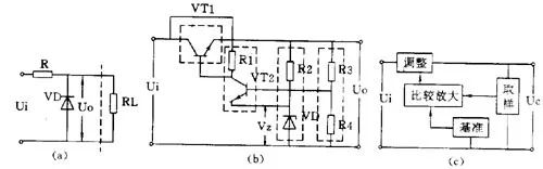
1.Zener Diode Shunt Regulator:
The simplest form involves a Zener diode in parallel with the load, seen in Figure 4(a), providing a stable output voltage equal to the Zener voltage (VZ), with R as a current-limiting resistor.
2.Series Voltage Regulator:
Commonly used due to its feedback and amplification, shown in Figures 4(b) and 4(c). It detects changes in output voltage via a sampling circuit (R3, R4) and compares them to a reference voltage (VZ). Adjustments occur through an amplifier (VT2) impacting the control element (VT1), stabilizing the output voltage.
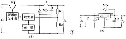
3.Switching Regulators:
Known for high efficiency and compact size, these regulators operate with the control element functioning as a switch. Their basic principle is outlined in Figure 4(d), where electrical energy storage elements (inductor L and capacitor C) and a freewheeling diode (VD) enable efficient voltage stabilization.
4.Integrated Voltage Regulators:
Advanced integrated solutions like the three-terminal regulators (CW7800 series for positive voltage, CW7900 for negative) offer simplicity and reliability. These devices, with outputs ranging from 5V to 24V, require minimal external actual components and deliver precise regulation, as demonstrated in Figure 4(e).
Mastering these circuits enables the creation and analysis of complex electronic systems, ensuring devices receive stable, suitable electrical power to function efficiently.


