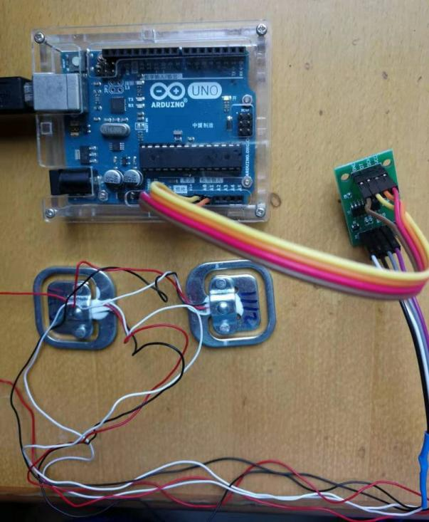
Arduino Hands-On- HX711 Load Cell Amplifier Module
Experiment: 50kg Load Cell Weight Sensor Module (Strain Gauge Half-Bridge Type)

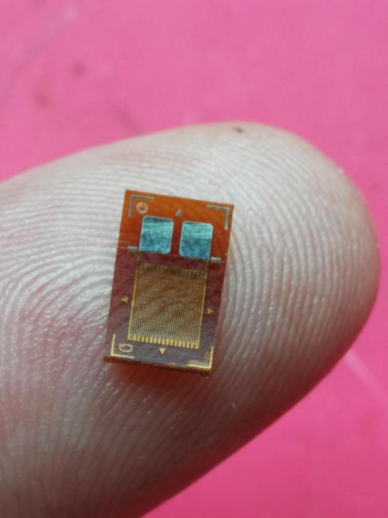
Strain Gauge
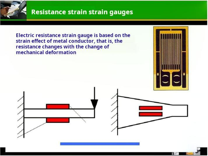
A component composed of sensitive grids and other materials used to measure strain. The working principle of a resistive strain gauge is based on the strain effect, which means that when a conductor or semiconductor material undergoes mechanical deformation due to external forces, its resistance changes accordingly. This phenomenon is known as the "strain effect."

Strain Effect
The phenomenon where the resistance of a metal conductor changes with the magnitude of the mechanical deformation (extension or compression) it experiences under stress is known as the metal's resistance strain effect. This phenomenon of changing resistance is referred to as the "strain effect." By attaching a strain gauge to the material being measured, the strain experienced by the material due to external forces is transmitted to the strain gauge, causing a change in the strain gauge's resistance. By measuring the change in resistance of the strain gauge, the magnitude of the mechanical quantity being measured can be determined.
The application scope of the strain effect is extensive and can measure physical parameters such as strain, stress, torque, displacement, acceleration, and torque. There are two application modes for resistive strain gauges: one is to attach the strain gauge to an elastic rigid body to form a balanced bridge circuit, which is then connected to a conversion circuit to create a dedicated strain sensor; the other is to attach the strain gauge directly to the object being measured and then connect it to a dedicated strain meter to directly read the strain value.
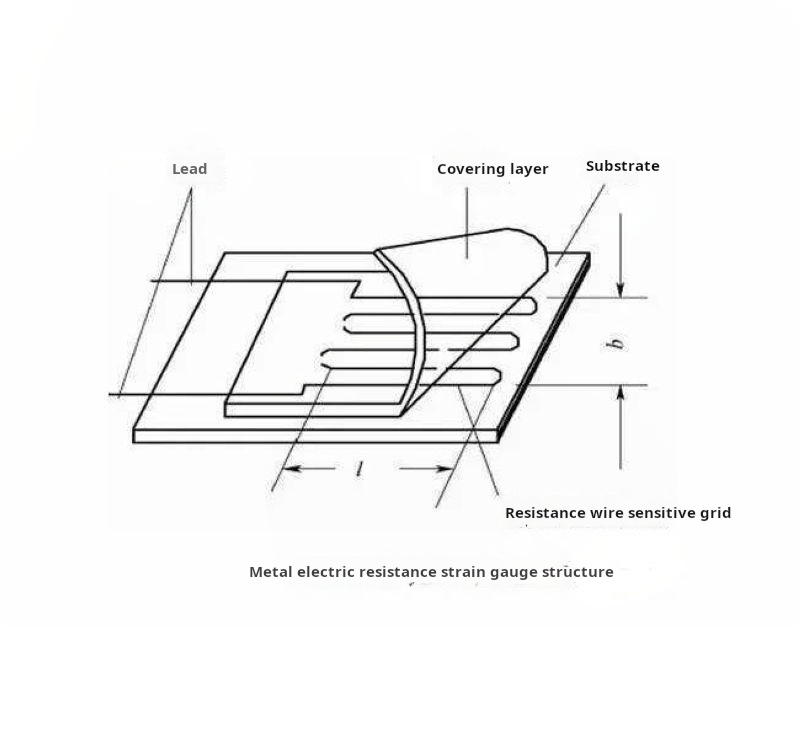
Resistive Strain Gauge
The working principle of a resistive strain gauge is based on the strain effect, where the resistance of a conductor or semiconductor material changes correspondingly when it undergoes mechanical deformation due to external forces. This phenomenon is known as the "strain effect." Semiconductor strain gauges are made of semiconductor materials, and their operation is based on the piezoresistive effect of semiconductor materials. The piezoresistive effect refers to the phenomenon where the resistivity of a semiconductor material changes when subjected to external forces along a certain axis. Strain gauges are components composed of sensitive grids and other elements used to measure strain. When in use, they are securely attached to the measuring point of a component. When the component experiences force and strain at the measuring point, the sensitive grid deforms, causing a change in its resistance. This change in resistance is measured by specialized instruments and converted into the strain value at the measuring point. There are various types of metal resistive strain gauges, with common forms being wire-type and foil-type strain gauges. Foil-type strain gauges are sensitive elements made based on the strain-resistance effect, where metal foil is used as the sensitive grid to convert the strain of the tested component into a change in resistance.
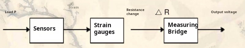
Working Principle of Weighing Sensor
A weighingsensoris a conversion device used to convert weight signals or pressure signals into electrical signals. Weighing sensors utilize metal resistive strain gauges to form a measurement bridge, taking advantage of the principle that metal resistance wire elongates and thins under tension, causing an increase in resistance. This effect is based on the variation of metal resistance with strain. Metal resistance possesses the property of hindering the flow of electric current, where generally, the thinner and longer the metal wire, the higher its resistance value. When a metal resistance wire is subjected to external forces and contracts or expands, its resistance value will change within a certain range. Therefore, when attaching a metal wire (or film) to the object being measured, as the object stretches or contracts under external forces, the metal resistance wire (or film) will proportionally extend or contract, resulting in a corresponding change in resistance. Weighing sensors involve attaching metal resistive strain gauges to metal weighing beams to measure weight signals.
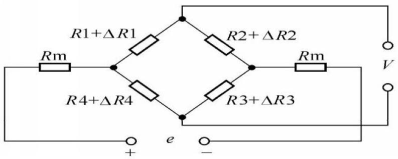
Bridge Measurement Circuit
A resistive strain gauge weighing sensor consists of two main components: an elastic sensitive element that converts the measured weight into strain values in the elastic body, and a resistive strain gauge that serves as the sensing element for the elastic body resistive strain gauge weighing sensor. When the sensor is not under load, the elastic sensitive element does not experience strain, the strain gauge attached to it remains undeformed, the resistance value remains constant, the bridge is balanced, and the output voltage is zero. When the sensor is under force, i.e., when the elastic sensitive element is subjected to a load P, the strain gauge deforms, the resistance changes, the bridge loses balance, and there is an output voltage.
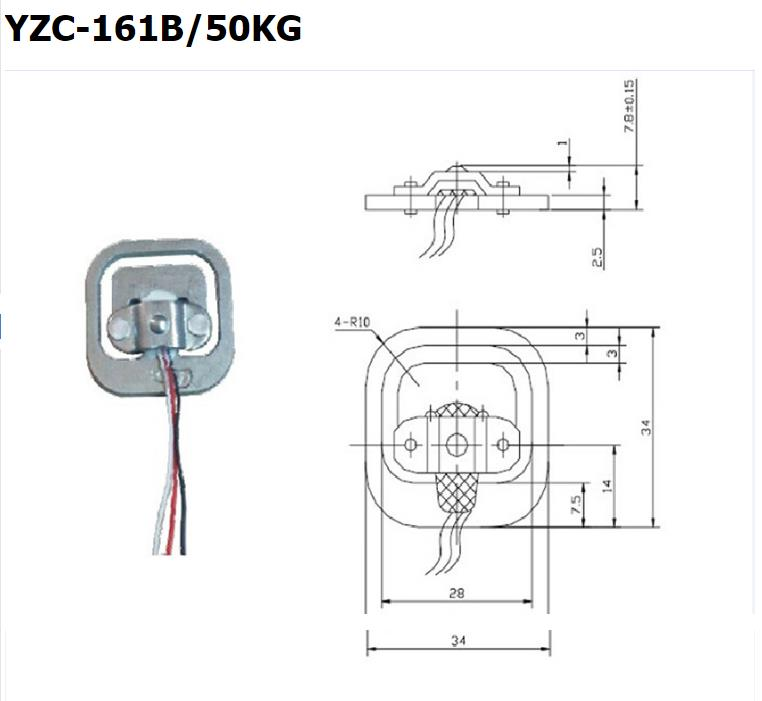
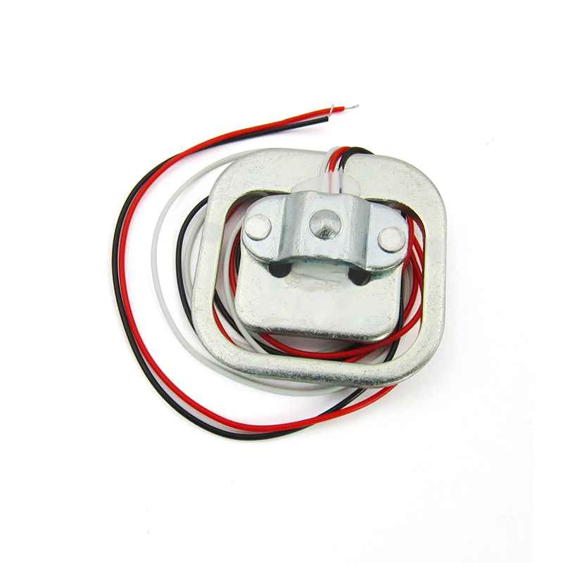
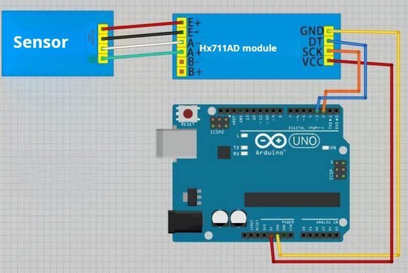
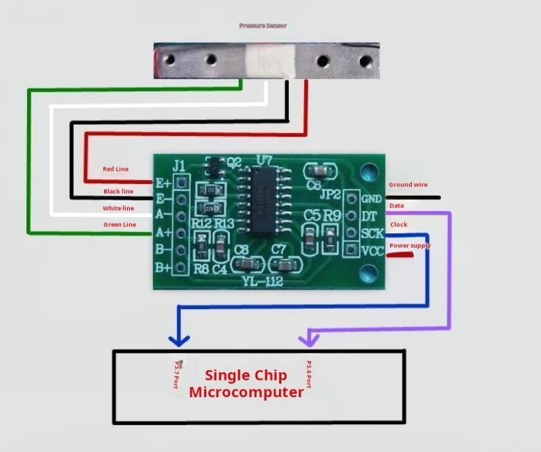
The internal structure consists of a 1000-ohm half-bridge strain gauge, and the range is a 50kg load sensor with a half-bridge configuration. When measuring, external forces should be correctly applied to the outer sides of the sensor. The strain beam part of the E-shaped sensor (the central arm where the strain gauge is attached, with white adhesive covering) and the outer sides should form opposing shear forces, meaning that the central strain beam must be able to bend under force, and there should be no obstruction on the opposite side of the strained face of the strain beam.

The sensor internally consists of a set of half-bridge strain gauges, and there are three possible methods of use:
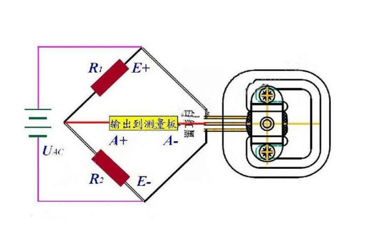
• Using one sensor combined with an external resistor to form a full-bridge measurement, with a range equal to the range of one sensor: 50kg. This method requires high precision for the external resistor.
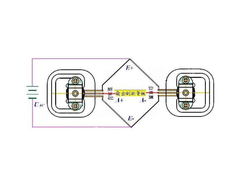
• Using two sensors to form a full-bridge measurement, with a range equal to the sum of the ranges of the two sensors: 50kg x 2 = 100kg.
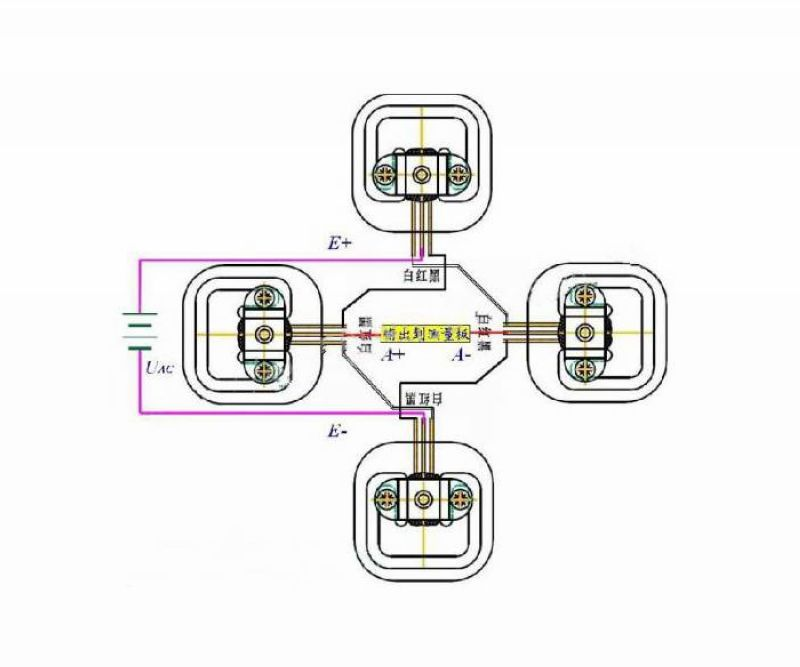
• Using four sensors to form a full-bridge measurement, with a range equal to the sum of the ranges of the four sensors: 50kg x 4 = 200kg.

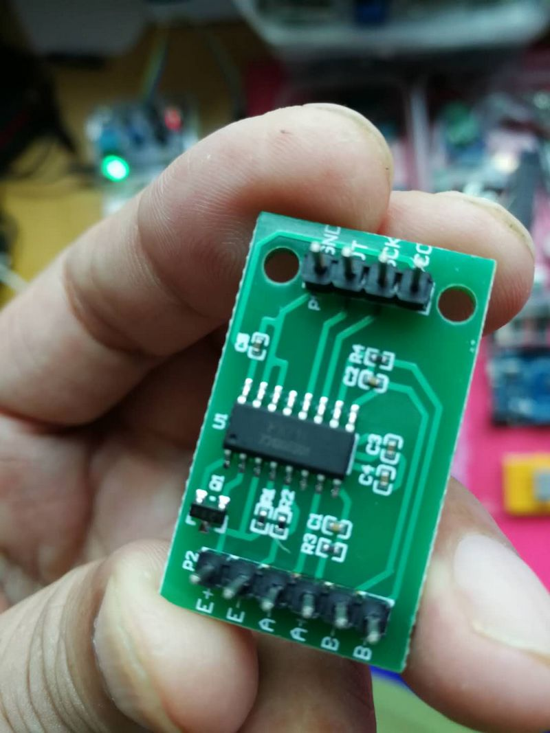
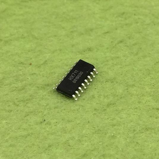
HX711 24-bit Precision AD Weight Module

HX711is a 24-bit A/D converter chip designed specifically for high-precision electronic scales. Compared to other chips of the same type, this chip integrates peripheral circuits, such as voltage regulators and on-chip clock oscillators, eliminating the need for additional external circuits. It boasts high integration, fast response speed, and strong anti-interference capabilities. This not only reduces the overall cost of the electronic scale but also enhances its performance and reliability. The interface and programming of this chip with the backend MCU are straightforward, as all control signals are pin-driven without the need for internal register programming. The input selection switch allows for the choice of Channel A or Channel B, which can be connected to its low-noise programmable amplifier internally. Channel A has programmable gains of 128 or 64, corresponding to full-scale differential input signal amplitudes of ±20mV or ±40mV, respectively. Channel B has a fixed gain of 32 for system parameter detection. The chip's built-in voltage regulator can directly power external sensors and A/D converters within the chip, eliminating the need for additional analog power supplies on the system board. The chip's clock oscillator requires no external components, and the power-on auto-reset function simplifies the initialization process during startup.


Main Parameters:
Full-Scale Differential Input Range V(inp)-V(inn) ±0.5(AVDD/GAIN) V
Input Common Mode Voltage Range AGND+0.6 AVDD-0.6 V
Using On-Chip Oscillator, RATE = 0 10
Using On-Chip Oscillator, RATE = DVDD 80
External Clock or Crystal Oscillator, RATE = 0 fclk/1,105,920
Output Data Rates:
External Clock or Crystal Oscillator, RATE = DVDD fclk/138,240 Hz
Output Data Encoding: Binary Complement 800000 7FFFFF (HEX) RATE = 0 400
Output Reference Voltage (VBG): 1.25 V
External Clock or Crystal Oscillator Frequency: 1-11.0592-30 MHz
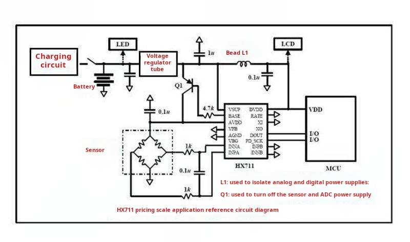
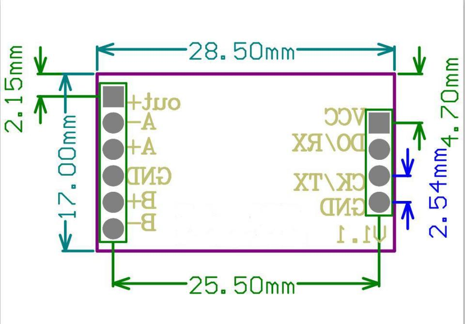
The module utilizes the 24-bit high-precision A/D converter chip HX711, designed specifically for high-precision electronic scales. It features two analog channel inputs and an internally integrated 128x gain programmable amplifier. The input circuit can be configured to provide bridge voltage for bridge-type (such as pressure, weighing) sensor mode. This module is an ideal high-precision, low-cost sampling front-end module. It samples with the HX711 24-bit AD chip, providing dual-channel differential input. Fully surface-mounted with machine soldering, equipped with metal shielding, and available in straight and bent pin options, meeting various installation and soldering methods. The board includes two 47uF tantalum capacitors, ensuring sufficient material usage, built-in pull-up resistors, and reserved CPU soldering positions, making it suitable for self-developing a variety of sensor-related applications.
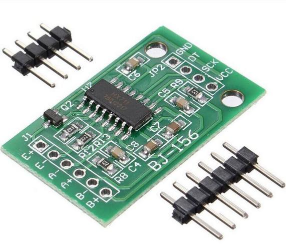

Module Schematic Diagram
Module Key Features:
• Equipped with metal shielding for strong anti-interference capabilities, and reserved CPU (STC15F104) position for self-upgrade and secondary development.
• Two selectable differential inputs
• Internally low-noise programmable amplifier with selectable gains of 32, 64, and 128
• Built-in voltage regulator circuit can directly power external sensors and A/D converters within the chip
• On-chip clock oscillator requires no external components, but can also utilize external crystal oscillators or clocks if necessary
• Power-on auto-reset circuit
• Simple digital control and serial communication: all controls are input via pins, no programming of internal registers required
• Option to select output data rates of 10Hz or 80Hz
• Synchronous suppression of 50Hz and 60Hz power interference
• Power consumption (including voltage regulator circuit): typical operating current < 1.7mA, standby current < 1μA
• Operating voltage range: 2.6 ~ 5.5V
• Operating temperature range: -20 ~ +85
Module Testing Method
Initial Rapid Assessment: Disconnect all connections to the module, only supply power to the module with 5V (connect VCC to +5V, GND to ground), then short the CK port of the module to ground. Next, measure the voltage between OUT+ and ground, which should be around 4.5V. Then measure the voltage between DO/RX and ground, which should be around 0V. If the voltages are within the expected range, it indicates that the module is 99% normal.
Comprehensive Testing: Construct a circuit using the test schematic provided, burn a test program into the microcontroller, and connect the module to the computer via a serial cable. Run a serial terminal program on the computer to receive the reading reports sent by the test circuit. If the readings are normal, it confirms that the module is functioning correctly.


Experimental Coding