RS-232: The Legacy Standard in Serial Communication
What is RS232?

Formal name: Recommended Standard 232
RS232's full name, Recommended Standard 232, was created by the Electronic Industries Alliance (EIA). It provided a common ground for device interoperability by having a recommended standard. EIA allowed different companies to design products, which could communicate with each other more conveniently, reducing the chaos and compatibility issues, which always appeared in the early days of electronic communication. The "Recommended" in the name shows that it serves as a guideline, but over time, it became widely adopted and almost a truly standard for serial communication in many applications.
EIA/TIA standardization process
The Electronic Industries Alliance (EIA) and the Telecommunications Industry Association (TIA) invited experts from different industries like electrical engineering, computer science, and telecommunications. They worked together to review the today's research and development in serial communication. They did surveys among manufacturers and end-users to understand their different requirements and then formulated a set of specifications. These specifications were then tested and refined over time. Multiple rounds of discussions, revisions, and field trials were carried out before the final standard was approved and released, laying the foundation for modern serial communication protocols.
Voltage-based serial communication protocol
RS-232 is a voltage-based serial communication protocol.In the RS232 protocol, information is sent one bit at a time through a single communication line. It uses specific voltage levels to represent binary values. A negative voltage range, usually between -3V and -15V, signifies a logic 1 (mark), while a positive voltage range, from +3V to +15V, signifies a logic 0 (space). This significant voltage difference offers a certain level of noise resistance, essential for dependable data transfer. It is suitable for short-to medium-range communication to encode data by use of voltage levels, as the signal can be clearly distinguished from background noise.
RS232 Serial Port
At the heart of countless electronic conversations lies the humble RS-232 serial port—a fundamental building block of modern communication. While newer technologies often steal the spotlight, this unassuming interface quietly keeps devices talking by passing data one bit at a time, like a patient messenger ensuring every piece of information arrives in perfect order.
What makes RS-232 standard truly special is how it translates digital chatter into something tangible. Unlike today’s sleek digital protocols, RS-232 relies on a clever system of voltage swings to whisper secrets between machines. A positive voltage might shout "1," while a negative voltage murmurs "0," creating a language of electrical pulses that travels reliably across cables—though it prefers to keep conversations short, rarely stretching beyond 50 feet without help.
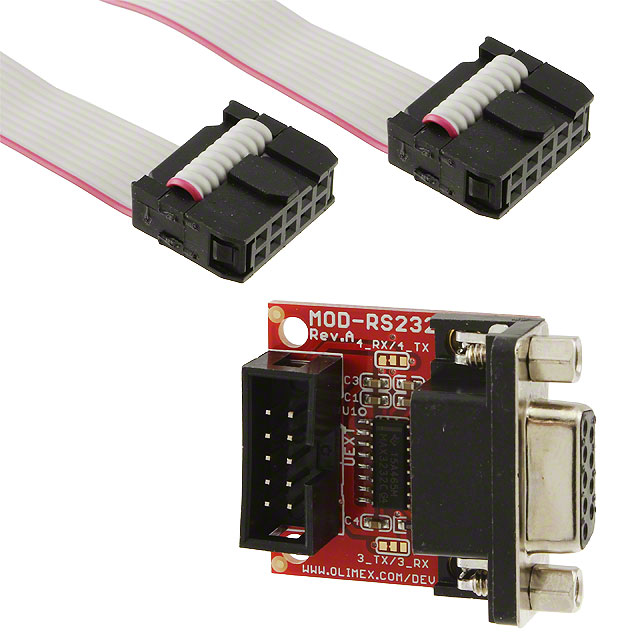
The RS-232’s personality shines through its iconic connectors. The compact DB-9 and its bulkier cousin, the DB-25, serve as the technology’s handshake points. Picture the nine-pin DB-9 as a tiny switchboard operator: Pin 2 diligently transmits outgoing messages (TXD), while Pin 3 leans in to catch incoming words (RXD). Together, they form a simple yet effective communication highway, with other pins standing ready to handle polite interruptions like "Wait, I’m not ready!" (RTS/CTS) or "Connection established!" (DTR/DSR).
You’ll still find RS-232 working overtime in places where reliability trumps speed. In factories worldwide, it’s the unsung hero linking gritty PLCs to their control panels, translating button presses into industrial actions. Embedded engineers keep a serial cable handy like a digital stethoscope, using it to diagnose microcontroller hiccups or whisper commands during late-night debugging sessions.
Though USB and Ethernet now dominate the conversation, RS-232 interface remains the wise elder of connectivity. Its straightforward design—no driver headaches, no complex negotiations—makes it the go-to choice when you need a connection that “just works.” In a world obsessed with speed, this decades-old standard endures as a testament to good design: sometimes, the simplest conversation is the one that outlives countless tech trends.
RS-232 Signaling
RS-232 signaling is the cornerstone of its communication capabilities. It operates using voltage levels to convey information between devices. In this system, a negative voltage range, typically from -3V to -15V, represents a logic 1 (also known as a "mark"), while a positive voltage range, from +3V to +15V, indicates a logic 0 (referred to as a "space"). This significant voltage differential helps in differentiating between the two states, even in the presence of some electrical noise.
The signaling is serial in nature, meaning data is transmitted one bit at a time. A start bit, always a logic 0, kicks off the transmission of each character. After the start bit, the actual data bits (usually 5-8 bits depending on the configuration) are sent, followed by an optional parity bit for error detection and one or more stop bits, which are always logic 1s. This structured sequence allows the receiving device to accurately interpret the incoming data stream.
Control signals in standard RS-232 rely on these voltage-based signals. For example, when a device wants to send data, it sets the RTS signal to a particular voltage level to indicate its intention. The receiving device then responds with the CTS signal, letting the sender know if it's ready to receive the data. This signaling mechanism ensures smooth and reliable communication between RS-232-connected devices.
Data Format
Start/stop bits configuration
In RS-232 communication, data is sent in a serialized format. Each character is framed by start and stop bits. A start bit, which is always a logic 0, signals the beginning of a new character. After the data bits (usually 5-8 bits representing the actual character) are transmitted, one or more stop bits, always logic 1, mark the end of the character. For example, a common configuration is 1 start bit, 8 data bits, 1 parity bit, and 1 stop bit. This setup helps the receiver synchronize with the incoming data stream.
Parity bit implementations
The parity bit is used for basic error detection. There are different types of parity, including even parity, odd parity, and no parity. In even parity, the number of 1s in the data bits and the parity bit combined is made even. For odd parity, the count is made odd. If the receiver detects a parity violation, it knows that an error may have occurred during transmission. For applications where high-reliability is not crucial, no parity can be used, reducing the overhead of data transmission.
Common data frame structures
A typical RS-232 data frame consists of the start bit, data bits, parity bit (if used), and stop bits. The structure ensures that the data is transmitted in an organized manner, allowing the receiving device to accurately interpret the incoming information.
Connectors
DB-9 Connector
In the world of serial communication, the DB-9 connector plays the role of a trusty messenger—small enough to squeeze into tight spaces but tough enough to keep serial devices chatting for decades. Imagine a tiny metal tongue with nine “fingers” (pins) arranged in two neat rows—a design so cleverly compact it became the go-to choice for everything from chunky 90s laptops to industrial gadgets where real estate is precious.
Pin 2, The Talkative Friend Meet the social butterfly of the group: Pin 2, aka Transmit Data (TXD). This pin is always ready to spill the tea, acting as your computer’s megaphone to the outside world. When your keyboard clatters or a sensor wakes up, Pin 2 translates those digital thoughts into voltage whispers, sending them one letter at a time to waiting devices like modems or printers—like passing notes in class, but with perfect punctuation.
Pin 3, The Good ListenerEvery talker needs an audience, and Pin 3 (Receive Data) is all ears. While Pin 2 shouts into the void, Pin 3 leans in to catch every word coming back—be it a modem’s dial-up screech or a GPS module’s coordinates. Picture it as a loyal friend nodding along, turning electrical murmurs into something your computer actually understands. Together, Pins 2 and 3 form a conversational tango, proving even machines need give-and-take to build relationships.
Pin 5, The Peacekeeper (Signal Ground)Behind every great duo is an unsung hero, and Pin 5—the Signal Ground—is the mediator keeping the peace. Like the Earth beneath our feet, it gives all those chatty signals a common reference point to avoid misunderstandings. Without this steady foundation, voltages might throw tantrums, letters could arrive scrambled, and the whole conversation could devolve into digital gibberish. It’s the glue holding the RS-232 universe together.
Pins 1, 4, 6, 7, and 8 are used for various control and status signals. For instance, pin 4 is the Data Terminal Ready (DTR) pin. When a DTE device sets this pin high, it indicates to the DCE device that it is ready to communicate. Pin 7 is the Request To Send (RTS) pin. The DTE uses this pin to signal to the DCE that it wants to send data. The DCE then responds using the Clear To Send (CTS) pin (pin 8), indicating whether it is ready to receive the data. These control signals play a crucial role in flow control, ensuring that data is transmitted and received accurately.
DB-25 Connector
The DB-25 connector was one of the original connectors used for RS-232 communication. It has 25 pins, providing more flexibility and functionality compared to the DB-9 connector.
Pin 2 is the Transmit Data (TXD) and pin 3 is the Receive Data (RXD), similar to the DB-9 connector. However, the DB25 offers additional data lines in some configurations. For example, it has secondary data channels that can be used for transmitting additional data simultaneously or for backup communication. Pin 7 is the Signal Ground (SG), which serves the same purpose as in the DB-9 connector, providing a common electrical ground for the entire RS-232 circuit.
The DB-25 connector has more extensive control and status signals. Pins 4 and 5 are the Request To Send (RTS) and Clear To Send (CTS) pins respectively, which are used for hardware-based flow control. Pins 6, 20, and 22 are Data Set Ready (DSR), Data Terminal Ready (DTR), and Ring Indicator (RI) pins. The DSR pin indicates that the DCE is ready to operate, the DTR pin shows the readiness of the DTE, and the RI pin is used to indicate an incoming call in the case of a modem.
What is RS232 used for?
Serial to USB Adapters
In today's digital landscape, the prevalence of USB (Universal Serial Bus) ports has transformed the way devices connect and communicate. However, many legacy devices and industrial equipment still rely on RS-232 for communication. Serial to USB serial adapters bridge this gap, enabling seamless integration between the older RS232 devices and modern USB-enabled systems.
These adapters are small, plug-and-play devices that convert the serial signals of RS-232 into USB signals and vice versa. They are widely used in scenarios such as connecting an old - fashioned serial printer to a new computer that only has USB ports or integrating industrial control systems with RS-232 interfaces into a modern USB-based network. Serial to USB adapters simplify the connection process, eliminating the need for complex and often expensive hardware modifications. They also offer a more convenient and compact solution compared to using dedicated RS-232 ports, which may not be available on all modern devices.
Role of FTDI Chipsets
FTDI (Future Technology Devices International) chipsets play a crucial role in serial to USB adapters. FTDI has developed a range of integrated circuits that are specifically designed to handle the conversion between serial and USB protocols.
One of the key functions of FTDI chipsets is to manage the data transfer between the RS-232 and USB interfaces. They are capable of translating the serial data format, including start/stop bits, parity bits, and data bits, into a format that is compatible with the USB protocol. This includes handling the different data rates and signal levels of RS-232 and USB.
FTDI chipsets also provide drivers that are compatible with various operating systems, such as Windows, macOS, and Linux. These drivers enable the operating system to recognize the serial to USB adapter as a standard serial port, making it easy for software applications to communicate with RS232 devices through the adapter. This seamless integration with operating systems simplifies the user experience, as there is no need for complex configuration or custom-developed drivers in most cases.


