What Is a Rheostat: Working, Types, and Potentiometer Difference
| Table of Contents |
What Is a Rheostat and How Does It Function?
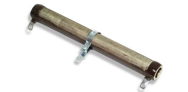
A rheostat is a variable resistor used to regulate circuit current, typically employing a high-power wire-wound structure. Its core function involves altering the equivalent resistance by changing the length of the resistive path, thereby enabling precise control of circuit current through Ohm's Law. While often referred to as a variable resistor, a rheostat is specifically designed to control current in a circuit by being connected in series with the load.
Key characteristics of rheostats include:
• Two-terminal device: Only two terminals are required during core operation to achieve current regulation;
• Wire-wound resistor: Primarily employs a wire-wound structure, suitable for high-power applications. This design forms the core foundation for meeting high-current regulation demands
• Current control: Its primary function is to alter circuit current through resistance adjustment rather than voltage regulation, representing a core distinction from other variable resistive devices.
Basic Construction of a Rheostat
The fundamental structure of a rheostat comprises core components that work together to ensure stable resistance adjustment. Key components and their operating principles are as follows:
• Ceramic Core: Serves as the core support structure, offering excellent high-temperature resistance and insulation properties, providing a stable foundation for the wound resistance wire.High-power wirewound rheostats from brands like Ohmite or Vishay (available at
Unikeyic is standard for industrial load testing.
• Resistive Element: Typically wound resistance wire wrapped around the ceramic core, forming the core component determining the rheostat's resistance value;
• Sliding Arm/Slider: Moves along the resistance wire, altering the contact point to adjust the length of the resistive path connected to the circuit;
• Terminals: Facilitate connection between the rheostat and external circuits. While featuring a three-terminal structure, only two terminals are actively used during operation (one connecting to the resistance wire and the other to the slider arm).

As the slider moves along the wire-wound resistor, the effective resistance length connected to the circuit changes, thereby adjusting the equivalent resistance. It is worth noting that the wire-wound structure's characteristics make it suitable for high-current, high-power applications, but it also results in a relatively larger physical size.
Rheostat Symbols and Circuit Diagrams
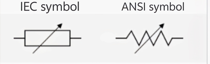
Multiple standards exist for rheostat circuit symbols, with ANSI and IEC being the most common. For a deeper understanding of the standard variable resistor symbol, you can refer to our detailed guide. Additionally, symbols must differentiate terminal usage scenarios:
• ANSI symbol: Typically depicted with a zigzag line and a diagonal arrow, where the arrow signifies the "variable" characteristic;
• IEC symbol: Often depicted as a rectangle with a diagonal arrow, where the "rectangle + arrow" combination conveys the variable resistance property;
• Terminal Symbol Specifications: Rheostats have three-terminal symbols, but simplified two-terminal symbols are commonly used in practice since only two terminals connect to the circuit. Additionally, preset rheostats include a fine-tuning indicator in their symbols to distinguish them from standard rheostats.
From a basic application circuit perspective, rheostats are typically connected in series. The most fundamental circuit configuration is the "power source–rheostat–load" series loop. In the circuit shown below, the current path flows from the positive terminal of the power source → rheostat → load → negative terminal of the power source. According to Ohm's Law, when the rheostat's resistance increases, the total circuit current decreases accordingly.

How Does a Rheostat Work in a Circuit?
Ideally, a rheostat acts like a current valve. Its core job in a circuit is adjusting current, which it does by changing its effective resistance — and this working principle lines up perfectly with Ohm's Law. In a constant-voltage series circuit, the circuit current is inversely proportional to the total resistance, just as the formula I=U/R shows. When the rheostat's resistance increases, the total circuit resistance rises, causing the current to decrease accordingly. Conversely, reducing the rheostat's resistance increases the current. Structurally, moving the slider arm effectively alters the length of the resistive path. When the slider moves toward one end of the resistive wire, the length of the wire connected to the circuit decreases, reducing the equivalent resistance. Moving toward the other end increases the connected length, increasing the equivalent resistance. This enables continuous, smooth current adjustment.
A numerical example clarifies this: Consider a series circuit with a constant 12V power supply and a 10 Ω load resistor (ignoring the power supply's internal resistance). When the rheostat is set to 2 Ω, the total circuit resistance Rtotal = 10 Ω + 2 Ω = 12 Ω. Applying Ohm's Law, the current I = 12 V / 12 Ω = 1 A. When the sliding arm is moved to increase the rheostat's resistance to 10 Ω, the total resistance becomes Rtotal = 10 Ω + 10 Ω = 20 Ω. At this point, the current I = 12 V / 20 Ω = 0.6 A, clearly demonstrating the principle that increasing resistance reduces current.
It is crucial to note that rheostats generate power loss due to current flow during operation, leading to ohmic heating—a practical issue requiring careful consideration in circuit design. Power loss can be calculated using the formula P = I²R. Excessive power loss combined with inadequate heat dissipation may cause excessive temperature rise in the device, compromising adjustment accuracy and potentially damaging the rheostat and surrounding components.

Linear, Rotary, and Preset Rheostats
Based on operating methods and structural differences, rheostats are primarily categorized into three types: linear rheostats (also known as sliding rheostats), rotary rheostats, and preset rheostats. The definitions, application scenarios, and advantages/disadvantages of each type are as follows:
• Linear Rheostat: Defined as a rheostat that alters resistance by sliding a wiper along a linear track, offering a long adjustment range and intuitive operation. Typical applications include laboratory teaching demonstrations (e.g., verifying Ohm's Law experiments) and high-power adjustable load testing equipment. Advantages include high adjustment precision, uniform current variation, and ease of observing the adjustment process. Disadvantages include large size, high space requirements, unsuitability for miniaturized circuit integration, and wear on the sliding guide that can affect stability.
• Rotary Rheostat: Adjusts resistance by rotating a knob that moves a sliding arm along a circular resistive wire. Offers convenient operation and a compact structure. Typical applications include everyday light dimmers, electric fan speed switches, and small motor speed control circuits in industrial equipment. Advantages include compact size, easy installation, and compatibility with most small-to-medium circuits. Disadvantages are a limited adjustment range, weaker heat dissipation than linear wirewound types in high-current applications, and slightly less smooth continuous adjustment compared to linear rheostats.
• Preset Variable Resistors: Miniature resistors specifically designed for circuit calibration, requiring tools like screwdrivers for adjustment. Once set, resistance values remain stable. Typical applications include PCB (printed circuit board) parameter calibration, amplifier bias current fine-tuning, and sensor signal calibration circuits. Advantages include compact size, high integration, high adjustment precision, and strong resistance stability. Disadvantages are low power ratings, inability to withstand frequent adjustments, suitability only for static calibration scenarios, and inability to meet dynamic current adjustment requirements.

Power Ratings, Resistance Range, and Taper
Core selection parameters for rheostats include rated power, resistance range, and adjustment characteristics, which directly determine their circuit applicability:
Common power ratings span from several watts to hundreds of watts. Low-power models (1W-5W) suit fine-tuning circuits in electronic devices, medium-power models (10W-50W) accommodate speed control for small-to-medium motors, while high-power models (50W-200W) are primarily used for industrial-grade adjustable loads. Resistance ranges typically span from several ohms (suited for high-current, low-resistance circuits) to several thousand ohms (suitable for low-current signal regulation), requiring matching based on total circuit resistance and required adjustment range.
Regarding adjustment characteristics, the linear taper represents the most fundamental type. Resistance values change linearly with the slider's position, meaning the distance the slider travels is directly proportional to the change in resistance. This provides uniform current regulation and is suitable for scenarios requiring consistent adjustment precision, such as laboratory teaching or linear load regulation. While logarithmic tapers are standard for low-power potentiometers in audio, industrial-grade rheostats are almost exclusively linear. Using a linear rheostat for power control provides more predictable heat distribution across the resistive element.
The following table provides typical application examples for different parameter combinations:
|
Power Rating |
Resistance Value |
Typical Applications |
|
3 W |
100 Ω–1 kΩ |
Audio Equipment Volume Control |
|
20 W |
10 Ω-100 Ω |
Home fan speed control |
|
100 W |
5 Ω-50 Ω |
Industrial Adjustable Load Testing |
When selecting engineering components, prioritize safety margins for power and temperature rise. Avoid the "just enough" approach. Industry best practices recommend reserving a 50%-100% power margin for rheostats. This means actual operating power should not exceed 50%-67% of the rated power. This margin compensates for the temperature rise caused by ohmic heating, ensuring long-term stable operation and preventing resistance drift or burnout due to overheating.
What Is the Difference Between a Potentiometer and a Rheostat?
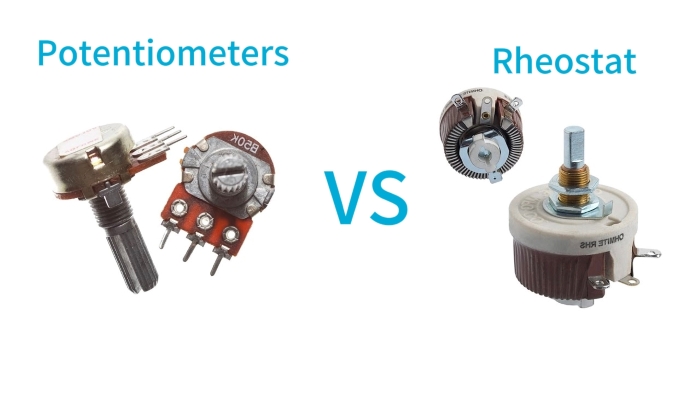
The core distinction between rheostats and potentiometers can be summarized as follows: While structurally similar—both comprising resistive elements and a sliding arm—their core functionalities and typical applications differ fundamentally. A potentiometer is a three-terminal device primarily functioning as a voltage divider for voltage control or position sensing. Conversely, a rheostat essentially employs its three-terminal structure as a two-terminal device, achieving current limiting by being connected in series within a circuit. Its core purpose is current control or power regulation.
A common practice in engineering involves wiring a potentiometer as a rheostat (connecting only one resistive terminal to the wiper terminal) to function as a variable resistor. While this enhances device versatility, careful matching of power ratings is essential to prevent overheating and damage due to insufficient power handling capacity.
Potentiometer vs Rheostat (Tabular Comparison)
The following comparison table clearly illustrates the differences in core parameters and application scenarios:
|
Comparison Dimension |
Potentiometer |
Rheostat |
|
Purpose |
Voltage control, signal voltage division, position sensing |
Current control, power regulation, and current limiting |
|
Number of Terminals |
Three terminals (two resistor terminals + one slider terminal) |
Actual usage: two terminals (one resistor terminal + one sliding arm terminal) |
|
Connection method |
Can be connected in series or parallel; commonly used in a voltage-dividing configuration |
Only connected in series in the circuit |
|
Power Rating |
Primarily low power, suitable for signal-level adjustments |
Wider power rating range, supporting high-power wire-wound models |
|
Typical Applications |
Audio volume adjustment, dashboard brightness control, sensor position detection |
Lighting dimming, motor speed control, and industrial adjustable load testing |
What Is the Difference Between a Fixed Resistor and a Rheostat?
The fundamental difference between a fixed resistor and a rheostat lies in their resistance characteristics: a fixed resistor provides a constant, unchanging resistance value that cannot be adjusted; whereas a rheostat, as a type of variable resistor, offers continuously variable equivalent resistance through the movement of a sliding arm. To learn more about the comparison, check out our guide on fixed vs variable resistors.
In application scenarios, fixed resistors serve as fundamental circuit components primarily used for circuit biasing, signal voltage division, fixed current limiting, and other applications where resistance adjustment is unnecessary. Rheostats, however, are specifically designed for current limiting or power control scenarios requiring "adjustable" functionality—such as situations demanding fine-tuned current levels based on actual needs or adapting to varying load conditions. It's worth noting that in modern circuit design, many high-power adjustable applications have been gradually replaced by Active Control solutions, such as PWM-driven MOSFETs or IGBTs. These solid-state approaches offer significantly higher efficiency and minimal heat generation compared to the purely resistive energy dissipation of a rheostat.
Fixed Resistor vs Rheostat
Key parameters and application differences are summarized in the table below:
|
Comparison Dimensions |
Fixed Resistor |
Rheostat |
|
Applications |
Fixed current limiting, circuit biasing, signal voltage division, impedance matching |
Adjustable current limiting, current regulation, and power fine-tuning |
|
Cost |
Low cost, high cost-effectiveness for mass production |
Higher cost, greater structural complexity than fixed resistors |
|
Efficiency |
Stable efficiency with no additional adjustment losses |
Power loss occurs during adjustment, resulting in slightly lower overall efficiency |
|
Heat |
Constant heat generation, low difficulty in heat dissipation design |
Heat fluctuates with resistance changes, requiring a larger heat dissipation space |
|
Flexibility |
No flexibility; resistance is fixed and non-adjustable |
High flexibility, continuously adjustable resistance to adapt to different operating conditions |
In summary, when circuit requirements demand "fixed parameters and long-term stable operation," fixed resistors are the preferred choice. However, rheostats should still be considered when "on-site current/power fine-tuning," "adaptation to multiple load conditions," or "adjustable characteristics for educational demonstrations" are needed. Particularly in high-power linear regulation scenarios where high-precision control is unnecessary and cost sensitivity is high, or during rapid prototyping phases (where frequent BOM changes are undesirable), rheostats retain irreplaceable value due to their simple structure, high reliability, and ease of debugging.
What Are the Main Applications and Uses of a Rheostat in Electrical Circuits?
The core application value of rheostats lies in precisely regulating circuit current to control physical quantities such as load brightness, rotational speed, and temperature. They are widely used across multiple fields, including household electronics, industrial control, educational experiments, and circuit calibration, serving as typical power control devices. Rheostat applications are often based on the series current-limiting principle, adapting to different load requirements by altering their equivalent resistance. Specific application scenarios include:
Lighting, Heaters, and Motor Control
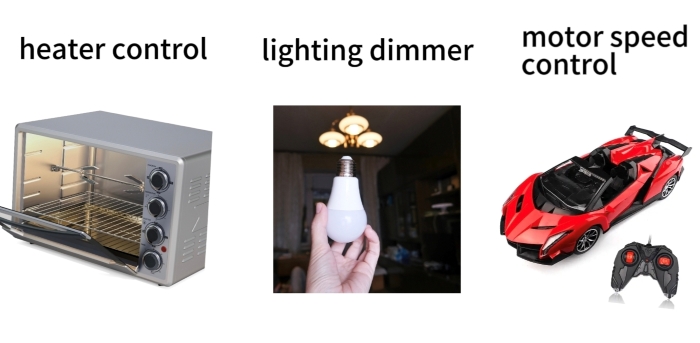
The typical connection method for these applications involves connecting the rheostat in series with loads such as light bulbs, heating elements, or motors. By adjusting the rheostat's resistance, the current in the series circuit is altered, thereby controlling the power output of the load. Specific application scenarios include:
• Lighting Dimming: Early household lighting dimmers often utilized rheostats, where rotating or sliding controls altered current levels to adjust bulb brightness. Although electronic dimming solutions (like PWM dimming) have become mainstream due to their high efficiency and low heat generation, rheostats remain common in educational experiments or simple circuits for lighting dimming.
• Motor Speed Control: In applications like toy cars and DIY small devices, rheostats offer a straightforward solution for motor speed regulation. By adjusting the current in series, they modify the input power to small DC motors, enabling continuous speed adjustment. This approach boasts low cost and circuit simplicity.
• Heating Control: In small ovens, simple heating devices, and similar equipment, rheostats enable basic temperature/power adjustment. By altering the current through heating elements, heating power is adjusted to indirectly control internal temperatures. This is suitable for scenarios with low precision requirements for temperature control.
Important Notes: In such applications, resistors exhibit significant power loss and ohmic heating during operation, resulting in low overall efficiency and substantial heat generation. Therefore, they are unsuitable for prolonged high-power continuous regulation, as excessive temperature rise may damage components. Adequate heat dissipation space must be provided.
Laboratory, Education, and Calibration Uses
Rheostats play an irreplaceable role in laboratories, education, and circuit calibration, particularly suited for scenarios requiring intuitive adjustment and variable parameters. Specific applications include:
• Educational Experiments: In physics or electrical engineering teaching experiments, laboratory rheostats are core components. For instance, in verifying Ohm's Law experiments, adjusting the rheostat alters circuit current to observe voltage-current relationships or plotting load V–I curves to help students intuitively grasp circuit parameter variations. Typical experiments include "Investigating Current Patterns in Series Circuits" and "Measuring V–I Characteristics of Resistive Components."
• Calibration and Fine-Tuning: Preset variable resistors (trimming resistors) are widely used in calibration circuits for PCB boards. Examples include adjusting bias current with trimming resistors in amplifier bias circuits to ensure stable operation, or regulating variable resistors in bridge balancing circuits to achieve equilibrium and guarantee measurement accuracy.
Such applications impose clear requirements on the rheostat's "repeatability" and "stability": Educational experiments demand consistent adjustment to ensure similar results across different operators; in calibration circuits, the trimmer resistor must maintain a stable resistance value after adjustment to prevent parameter drift from affecting circuit performance.
Typical Design Examples and Value Calculation
The core of rheostat selection involves determining parameters through resistance and power calculations, strictly following the steps: "Define Requirements → Calculate Range → Reserve Margin." The following details two typical design examples. Power calculation uses the formula P=I²R, with a safety margin reserved at 50%-100% based on engineering experience.
General Design Framework
Step 1: Define core parameters, including circuit operating voltage U and load current adjustment range I, ignoring power supply internal resistance (for simplified calculation scenarios).
Step 2: Calculate the required resistance range. Using Ohm's Law, R = U/I, first determine the load resistance R = U/I. Then, calculate the rheostat's maximum resistance, R (U/I) - R, and minimum resistance, R = 0 Ω (for ideal continuous adjustment scenarios).
Step 3: Calculate power and reserve margin: Identify the maximum power dissipation point. In a series circuit, the peak power loss on the rheostat occurs when its resistance equals the load resistance (Rrheostat =Rload). The rated power of the actual selected model must be ≥Ppeak×(1+50%∼100%) to ensure safety across the entire adjustment range.
The following table summarizes design parameters and selection recommendations for two typical scenarios:
|
Design Examples |
Core Parameters |
Resistance Range Calculation |
Power Calculation |
Recommended Resistance Value and Power Rating |
|
12V Power Supply + Bulb, Current 0–1 A Adjustable |
U=12V, I=0–1A; Load Resistance R=12 V/1A=12 Ω |
R = (12 V / 0.1 A) - 12 Ω = 108 Ω (using minimum current 0.1 A to prevent bulb failure from insufficient current); R = 0 Ω |
Peak power occurs when . |
Resistance range: 0–120 Ω (reserves adjustment margin); Rated power: ≥2 W (reserves 100% margin) |
|
24 V small motor, adjustable current 0.5–2 A |
U=24 V, I=0.5–2 A; Load resistance R=24 V/2 A=12 Ω |
R = (24 V / 0.5 A) - 12 Ω = 36 Ω; R = 0 Ω |
Maximum power dissipation P = (0.5 A) × 36 Ω = 9 W |
Resistance range: 0–40 Ω (with adjustment margin reserved); Rated power: ≥18 W (with 100% margin reserved) |
Engineering experience summary:
1. The recommended maximum resistance value of the rheostat should exceed the calculated value by 10%-20% to reserve an adjustment margin.
2. Prioritize power margin at 100%, i.e., rated power ≥ 2× calculated maximum power consumption; further increase margin in poor heat dissipation environments;
3. For high-current applications, prioritize wire-wound rheostats to ensure adequate power handling capacity.
How Do You Connect a Rheostat in a Circuit to Control Current?
The core principle for current control via rheostat integration is a series connection. Connect the circuit using the "terminal + slider arm" dual-terminal wiring method while strictly adhering to safety protocols. Proper wiring ensures stable current regulation and prevents component damage. Specific operational procedures and troubleshooting methods are outlined below.
Core Wiring Points: The rheostat must be connected in series with the load, using only one resistor terminal and the slider terminal. The unused third terminal is strongly recommended to be shorted to the slider (wiper) terminal. This safety measure ensures that if the slider momentarily loses contact due to wear or dust, the circuit resistance defaults to the maximum value of the rheostat rather than an infinite open circuit, preventing potential high-voltage arcs or circuit failure. Safety Precautions: Before wiring, ensure the circuit is de-energized to prevent electric shock or short-circuit risks from live operations. Prior to initial power-up, adjust the rheostat to its maximum resistance setting to avoid damaging the load or components due to excessive initial current.

Step-by-Step Wiring Procedure
Step 1: Verify Core Parameters and Match Device Specifications. First, determine the circuit's operating voltage, load current adjustment range, and load resistance value. Verify that the selected rheostat's resistance range and rated power match these parameters to prevent adjustment failure or device overheating due to mismatched specifications.
If parameter matching is uncertain, recheck the resistance and power calculation steps to ensure an adequate margin.
Step 2: Identify Terminal Types and Confirm Resistance Change Direction. Complete terminal selection: Distinguish the rheostat's two resistance terminals and one slider terminal via device markings or physical appearance. Then perform a multimeter check: Set the multimeter to resistance mode and measure the resistance between "one resistance terminal + the slider terminal." Slowly move the slider to observe whether the resistance changes continuously. Simultaneously record the relationship between the slider movement direction and the resistance change (e.g., clockwise rotation increases resistance) to confirm the terminal combination is valid.
If no resistance change is observed, the terminal combination may be incorrect. Switch to another resistance terminal and repeat the measurement.
Step 3: Power-Off Wiring to Ensure Series Topology. With the circuit completely de-energized, connect the rheostat in series between the power source and load. Specific wiring: - Connect the rheostat's resistive terminal to the power source's positive output terminal. - Connect the rheostat's sliding arm terminal to one end of the load. - Connect the other end of the load to the power source's negative terminal, forming a complete series circuit. Unused resistor terminals may be connected to the wiper terminal or left open as needed.
Ensure all connections are secure to prevent loose contacts. Verify the wiring topology; never connect the rheostat in parallel across the load terminals.
Step 4: Initial Power-Up and Gradual Adjustment After confirming correct wiring, set the rheostat's slider to maximum resistance before applying power. Slowly move the slider to reduce resistance while observing the load's operational state (e.g., bulb brightness, motor speed) and ammeter readings. Verify continuous, smooth current adjustment and ensure the adjustment direction aligns with expectations.
If the load fails to respond or exhibits abnormal current after power-up, immediately disconnect power for troubleshooting. Do not continue the adjustment.
Step 5: Check Heating and Stability, Optimize Solution. Allow the circuit to operate continuously for a period. Touch the rheostat housing (exercise caution to avoid burns) to check for excessive heating while observing the load's operational stability. If the rheostat exhibits significant overheating (housing becomes uncomfortably hot to the touch or discolors), replace it with a higher-power model or switch to a more efficient control solution such as PWM or MOSFET.
In high-power applications, ensure ample heat dissipation space around the rheostat and avoid placing it in close proximity to other heat-sensitive components.
Common Mistakes and Troubleshooting
In practice, incorrect wiring and improper component selection often cause circuit failures. Below is a troubleshooting guide based on real-world scenarios, presented in a three-column format ("Failure Symptom - Possible Cause - Countermeasure") to help quickly identify and resolve issues:
|
Fault Symptom (Example) |
Possible Cause |
Countermeasure |
|
After wiring a home lighting dimmer circuit, the circuit breaker trips immediately upon closing, and the rheostat surface becomes hot. |
Parallel connection of the rheostat across the load terminals causes a sudden drop in total circuit resistance, triggering a short circuit, or the selection of a rheostat with an insufficient power rating. |
1. Disconnect power, recheck wiring, and reconfigure to the correct series topology between the rheostat and the load; 2. Verify power calculations and replace with a rheostat of higher-rated power to ensure an adequate margin |
|
When adjusting the speed of a DIY car motor, the motor speed fluctuates between fast and slow, with accompanying vibration when the sliding resistor is adjusted. |
Sliding arm terminals are loose or have poor contact; wear and oxidation on the sliding arm and resistance wire cause unstable contact resistance. |
1. Disconnect power and inspect slider terminal connections to ensure wires are secure; 2. Connect unused resistor terminals in parallel with the slider terminal to enhance contact reliability; 3. Replace the rheostat if components show severe wear. |
|
During laboratory verification of Ohm's Law experiments, moving the rheostat's sliding arm causes no change in bulb brightness or ammeter reading |
Incorrect terminal selection (e.g., connecting two resistor terminals without connecting the sliding arm terminal), or the sliding arm is jammed, preventing effective resistance adjustment |
1. Re-test terminal combinations with a multimeter to ensure connection to "resistor terminals + sliding arm terminals"; 2. Inspect the sliding arm's mechanical structure, remove any obstructions, and ensure the sliding arm moves freely |
|
In industrial small-load test circuits, the rheostat burns out after 1-2 days of use; repeated replacements yield no improvement |
In high-power adjustable scenarios, excessive internal power loss in the rheostat causes low efficiency; insufficient power margin during selection |
1. Abandon the rheostat solution and switch to "PWM (Pulse Width Modulation) + fixed resistor" or a dedicated MOSFET driver solution; 2. If rheostat use is unavoidable, select a wire-wound rheostat with a power rating far exceeding calculated values and incorporate a dedicated heat dissipation device |
Core troubleshooting path summary:
1. Prioritize inspecting the wiring topology to confirm that the rheostat and load are connected in series
2. Measure resistance across the rheostat terminals and between terminals using a multimeter to verify continuous resistance adjustment capability;
3. Inspect the rheostat's appearance. Signs of discoloration, scorching, or deformation indicate device failure. Replace the unit and investigate selection or wiring issues.
Rheostat Selection Guide for Practical Designs
After completing the rheostat wiring and troubleshooting, the core focus of engineering design shifts to selection. The rationality of selection directly determines circuit stability, reliability, and cost control. A professional selection guide must comprehensively evaluate electrical parameters, mechanical characteristics, and operating environments to ensure precise matching with actual conditions.
|
Parameter Name |
How to Determine |
Engineering Recommendations |
|
Maximum Operating Voltage |
Determined based on the circuit's power supply voltage, it must cover the upper limit of power supply fluctuations |
Select a rated voltage ≥ 1.2 × maximum circuit operating voltage to prevent insulation breakdown due to voltage fluctuations |
|
Maximum Current / Rated Power |
Calculate the maximum current under worst-case conditions through circuit analysis. Determine the peak power dissipation point.
|
Prioritize power margin allocation of 50%-100%, i.e., rated power ≥ 2× calculated maximum power dissipation; in high-current scenarios, prioritize wire-wound structures to ensure power handling capability |
|
Target adjustment range |
Determine the required resistance range based on load current adjustment needs using Ohm's Law. |
The actual selected resistor range should be 10%-20% larger than the calculated value to reserve an adjustment margin, ensuring current coverage across the design range |
|
Linear/Rotary Type |
Determine based on application operation methods and installation space: prioritize linear rheostats for laboratories and high-power testing; prioritize rotary rheostats for small equipment and daily adjustments. |
Select linear rheostats for educational demonstrations or scenarios requiring precise linear taper; choose rotary rheostats for compact space and user-friendly operation |
|
Mounting Method |
Determine based on assembly location: Panel operation requires panel mounting; PCB integration typically requires Trimmer Potentiometers (through-hole or SMD) for calibration, while industrial panels require heavy-duty, bolt-on, or bushing-mount rheostats. |
PCB calibration scenarios prioritize trimmers; industrial equipment with panel operation requires panel-mounted types with knobs |
|
Operating Environment |
Determine based on actual equipment operating conditions, such as industrial high-temperature workshops or humid environments. |
For high-temperature environments, select components with temperature resistance ≥125°C; for humid environments, choose moisture-proof packaging to prevent contact oxidation and poor connectivity |
Selection Process
Step 1: Analyze operating conditions to determine worst-case current. Calculate or estimate current values under different conditions based on circuit load characteristics, identifying the maximum current scenario (e.g., load startup, peak supply voltage).
Step 2: Parameter calculation with a safety margin. Calculate the required maximum resistance value based on the worst-case current. Derive the maximum power dissipation using the power formula, then add a safety margin to determine the resistance range and power rating.
Step 3: Mechanical and Environmental Adaptation. Determine the type and mounting method based on installation space and operational requirements. Supplement with temperature resistance, moisture resistance, and other environmental characteristics as needed to finalize the selection.
Using the previous example of a "12V power supply + light bulb with 0–1A adjustable current":
Step 1: Determine the worst-case operating current as 1A (bulb's rated operating current);
Step 2: Calculate the peak power consumption (occurring at Rh = 12 Ω), which is Ppeak = 3 W. After reserving a 100% safety margin, select a rheostat with a resistance range of 0–120 Ω and a rated power ≥ 6 W to prevent burnout during adjustment;
Step 3: For simple dimming or educational applications, select a rotary panel-mounted wirewound rheostat with temperature resistance ≥85°C to finalize the selection.
Another example: "24 V small motor, adjustable current 0.5–2 A." Similarly, select a rotary wire-wound rheostat with a resistance range of 0–40 Ω and a power rating ≥ 24 W (based on a peak power of 12W at Rh = Rload with a 100% margin) to ensure reliability.
From Schematic to BOM: How to Source Rheostats Quickly
After selection, accurately convert schematic parameters to specific part numbers in the BOM. An efficient rheostat procurement process shortens R&D cycles and reduces supply chain risks. The core approach involves: 1. Defining critical parameters 2. Leveraging reliable supply chains to quickly match available stock 3. Setting reasonable parameter tolerance ranges to enhance alternative part matching efficiency
Quick Sourcing Process
Step 1: Organize Core Parameters. Extract key specifications from schematics: resistance range, rated power, type (linear/rotary/preset), mounting method (panel/PCB), and package dimensions to create a clear procurement parameter list.
Step 2: Search for in-stock inventory. Prioritize suppliers with extensive in-stock resources. Input core parameters to filter inventory and quickly identify compliant part numbers. For example, Unikeyic offers a full range of power-rated wirewound potentiometers and variable resistors, with numerous in-stock brands to rapidly match diverse application requirements.
Step 3: Verify Brand and Certifications. Confirm components are genuine and compliant with industry standards like RoHS. Leverage the supplier's supply chain support to validate part specifications match selection criteria, minimizing risks of counterfeit goods or specification mismatches.
Unikeyic's core advantages significantly enhance procurement efficiency: First, comprehensive in-stock brands covering products like wirewound rheostats and preset rheostats from major manufacturers, eliminating lengthy lead times. Second, same-day shipping services are particularly suited for equipment repairs, exact replacements, or rapid prototyping scenarios, drastically shortening delivery cycles. Third, guaranteed authentic components and professional supply chain support provide end-to-end assurance from parameter matching to part number verification, preventing R&D rework or equipment failures caused by component issues.
To further enhance procurement efficiency, we recommend setting reasonable parameter tolerance ranges during selection to facilitate rapid alternative component matching. Common parameter deviations and acceptable substitution strategies are outlined in the table below:
|
Common Parameter Deviations |
Acceptable Substitution Strategy |
|
Slightly higher resistance (≤20% of calculated value) |
If the adjustment range still covers the load current requirement, direct substitution is possible. If the minimum current is affected, appropriately reduce the series resistance on the load side for compensation. |
|
Power Rating Increased by One Level (e.g., calculation requires 2W, but only 3W is available in stock) Deviation in adjustment characteristics (e.g., design is linear, but the available unit is logarithmic) |
Direct replacement is possible. Greater power redundancy and improved stability are achieved. Only installation space compatibility needs verification. |
|
Deviation in adjustment characteristics (e.g., linear design vs. logarithmic actual product) |
Substitution is acceptable for simple dimming/speed control, but strictly prohibited for precision measurement or linear load testing, where Taper accuracy is critical. |
|
Installation method differences (e.g., panel-mounted design vs. desktop unit) |
Acceptable only for prototyping or emergency repairs; mass production must adhere to the original mechanical footprint to ensure structural integrity and thermal dissipation. |
Summary: The core principle from selection to procurement is "precise parameter matching + efficient supply chain coordination." First, lock core parameters through a scientific selection process. Then, leverage the stock availability, same-day shipping, and genuine product guarantees of premium suppliers like Unikeyic to rapidly transition from schematic to BOM. Simultaneously, reasonably set parameter tolerance ranges to enhance procurement flexibility and supply chain stability.