
Notes on Self-Studying STM32F10x Microcontroller Interrupts
Having previously used PIC and 8051 microcontrollers, I had never encountered the STM32 series of chips. Recently, I began delving into the STM32F10x series. Through my studies, I discovered that the interrupt system of the STM32 is quite unique compared to PIC and 8051, with a different response mechanism. Despite reviewing the relevant manuals and video materials several times, I still found myself somewhat confused. However, after practically writing code to configure the chip, I gradually started to gain some clarity. As such, I decided to document my experience as a form of summary notes. Of course, there may be inaccuracies or shortcomings in my descriptions, and I welcome corrections from everyone.
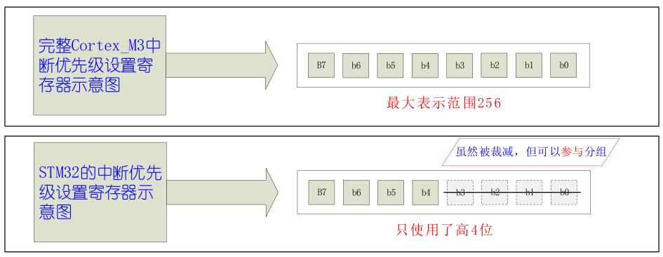
The STM32 utilizes the ARM Cortex-M3 core, which features 256 interrupt sources. Among these, the core itself has 16 interrupt sources, while external devices can have up to 240 interrupt sources. Each interrupt source comes with its own independent interrupt priority control register, which is an 8-bit register. Thus, each interrupt source within a complete Cortex-M3 core could theoretically have 256 levels of interrupt priority. However, this represents the entire interrupt architecture of the Cortex-M3 core.
In the context of STM32 chips, there aren't as many interrupt sources or priority levels. Specifically, in our STM32, we have the core's 16 interrupt sources and 68 interrupt sources from external devices. Since the STM32 does not employ all the interrupt sources available in the Cortex-M3, it also doesn't support the full range of 256 interrupt priority levels for programming. The interrupt priority setting registers for each interrupt source in the STM32 do not utilize the entire 8 bits; instead, only the upper 4 bits are used. Detailed information is provided in the diagram below:↓
Note: For the interrupt priority setting register of each interrupt source in STM32, these 4 bits need to be grouped before they can be used. We divide these 4 bits into 2 groups. The first group, which is the higher part, we refer to as "preemptive priority," and the second group, which is the lower part, we call "subpriority." In the Cortex-M3, the grouping mode for interrupts uses a specific register called the "Application Interrupt and Reset Control Register (AIRCR)" for configuration and storage. The AIRCR register is a 32-bit register, and we use three particular bits [bits 10, 9, and 8] within it to set and save the interrupt grouping status. These three bits have a specific name, "PRIGROUP." By setting the value of PRIGROUP, the priority format for each interrupt source in the entire system is defined and configured. The detailed grouping information is as follows↓.
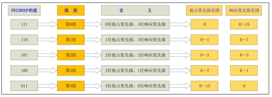
Explanation of Interrupt Priority Grouping: From the table above, we can see the relationship between the five defined interrupt groups and their corresponding priorities. For instance, if we set our chip's interrupt system to Group 2 (with PRIGROUP value = 101), then all interrupt sources on the chip will use 2 bits in the priority register for preemption priority (range from 0 to 3) and 2 bits for response priority (also ranging from 0 to 3). The values assigned to preemption priority and response priority determine the hierarchy; the smaller the value, the higher the priority it represents.
★ Note ★: According to the Cortex-M3 core specifications, regardless of how many bits are used to express priority, the lower bits in the priority register are always truncated, not the higher bits. The priority register follows the high-bit alignment principle. The interrupt priority register of the Cortex-M3 core mandates that during grouping, "at least one bit must be used for response priority." As a result, the full interrupt priority in the Cortex-M3 core can have up to 7 bits for preemption priority. However, the Cortex-M3 core allows the interrupt priority register to be grouped such that all bits are used for expressing response priority, with no bits left for preemption priority. In this mode, there will be no interrupt nesting among the interrupt sources. In the STM32 interrupt priority register, only the higher 4 bits are used to represent priority. During interrupt priority grouping, the truncated lower 4 bits can still participate in the grouping, resulting in Group 4 where 4 bits are used for preemption priority and none for response priority.
The difference between "preemption priority" and "response priority" is as follows: If two (or more) interrupt events occur simultaneously, the CPU will first handle the interrupt source with the higher preemption priority. If another event with even higher preemption priority occurs during this process, the CPU will pause the current program and switch to handle the higher-priority interrupt. Once the higher-priority interrupt is processed, the CPU will return to the interrupted program to continue its unfinished task, thus forming interrupt nesting. Both the Cortex-M3 core and STM32 stipulate: [Only higher-preemption-priority interrupts can preempt lower-preemption-priority interrupts, forming interrupt nesting] [If two (or more) interrupts with the same preemption priority occur simultaneously, they cannot form interrupt nesting and must be handled sequentially based on their response priority. In this case, STM32 will handle the interrupt events with lower response priority later, queuing them for execution.] [If two (or more) interrupts with the same preemption and response priority occur simultaneously, STM32 will respond to the interrupt event with the lower interrupt vector address first.]
"Pending" and "Unpending" of STM32 interrupts: Pending occurs when an interrupt request is made by a source while the system is processing an interrupt with the same or higher preemption priority. The subsequent interrupt cannot be executed immediately and remains pending. If not unpended, the interrupt system will respond to the pending interrupt when possible according to its priority. Pending can also be manually set via the ISPR[2] register in the interrupt set-pending registers structure (writing 0 has no effect). A pending interrupt will be responded to by the CPU under suitable conditions. Unpending is the opposite of pending. An interrupt source in a pending state can be manually unpended by operating the ICPR[2] register in the interrupt clear-pending registers structure (writing 0 has no effect). After unpending, the interrupt source will not be responded to.


