Inductor Color Code Guide: How to Read and Decode Inductor Color Bands Accurately
Introduction
In the world of electronic components, tiny inductors may seem unremarkable, but they play a crucial role in ensuring the stable operation of circuits. However, when faced with inductors that look similar but have different parameters, how can engineers and technicians quickly identify their key characteristics? The answer lies in the colorful color bands. Color coding is not only the "code book" for inductor parameters but also a silent assistant for efficient design, maintenance, and production.
Color rings convey core information, such as inductance value, tolerance range, and even temperature coefficient, through the combination and arrangement of colors. This standardized design eliminates the issue of text labels being difficult to read due to size constraints, while significantly enhancing component versatility and assembly efficiency. Whether it's precise tuning in high-frequency circuits or filtering applications in power modules, accurate interpretation of color rings ensures the reliability of circuit performance.
This article will delve into the encoding rules of inductor color rings, reveal the scientific logic behind the colors, and explore their irreplaceable role in modern electronics manufacturing. From basic interpretation to practical applications, let's uncover the technical mysteries behind these colorful stripes.
What Is a Color-Ring Inductor?
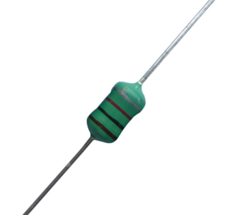
Color-coded inductors, also known as color-ring inductors, are fixed inductors that use colored rings to encode and label their parameters. Their primary function is to store and release energy through electromagnetic induction. They are commonly used in circuits alongside capacitors to form resonant circuits, filter circuits, and other similar configurations.
-
Color ring inductor ring structure
The core structure of a color-coded inductor consists of 4-6 colored rings arranged in a precise pattern. The position and color of each ring strictly comply with the standards set by the International Electrotechnical Commission (IEC). This is the physical basis for electromagnetic induction.
(1) Insulated wire coil
Typically, enameled copper wire or alloy wire is spirally wound to form a multi-layer or single-layer winding structure, with the number of turns directly determining the inductance value. The winding method (e.g., close winding, intermittent winding) affects the distributed capacitance and high-frequency characteristics of the inductor.
(2) Magnetic core/frame
The magnetic core is made of magnetic materials such as ferrite and alloy powder cores, which can be used to enhance magnetic fields and increase inductance. The hollow frame is a ceramic or plastic support that holds the coil in place and keeps the internal structure stable (when there is no magnetic core, it relies on an air magnetic circuit).
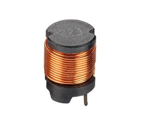
(3) Common winding shapes
| cylindrical winding |
Suitable for medium and low frequency circuits, simple process, low cost, easy to mass produce, and the most common winding method. |
 |
| Ring winding (ring core) | Low electromagnetic interference (EMI), good temperature characteristics, suitable for high-frequency and anti-interference circuits, complex winding process, and relatively high cost. | 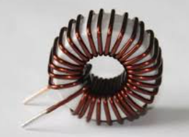 |
-
Key applications of color ring inductors
(1) Stable current
Color-coded inductors utilize their electromagnetic properties to impede changes in current. When the circuit current attempts to change abruptly, the inductor generates a counter-electromotive force (L·di/dt effect) to resist this change, thereby maintaining a relatively stable current. This characteristic is particularly prominent in the freewheeling circuit of switching power supplies, effectively suppressing current fluctuations caused by sudden changes in the load. For example, in a DC-DC converter, color-coded inductors work in conjunction with switching transistors to achieve smooth current transitions through an energy storage-release cycle.
(2) Energy storage
When current flows through a color-coded inductor, a magnetic field is established in the core (or hollow coil), storing energy in the form of magnetic energy (E = 1/2·L·I²).
This characteristic is crucial in the power conversion stage of switching power supplies: energy is stored during the conduction period of the switching transistor and released during the cutoff period, enabling continuous energy transfer.
(3) Energy buffering and transient protection
When there is a sudden change in instantaneous current in a circuit (such as when a relay switches or a motor starts or stops), the self-inductance effect of the inductor hinders the sudden change in current, acting as a buffer to protect sensitive components from voltage surges.
(4) Signal filtering
Utilizing the characteristic of inductance to "block high frequencies and pass low frequencies," color-coded inductors can be used in conjunction with capacitors to form LC filter networks. When connected in parallel with capacitors, they can form notch filters, and when connected in series with capacitors, they can form bandpass filters.
(5) Circuit matching
In RF/microwave circuits, color-coded inductors achieve impedance matching (eliminating signal reflection) and resonance matching (tuning capacitance) through specific reactance (XL = 2πfL).
(6) Magnetic coupling and energy transfer
In transformers or coupling circuits, color-coded inductors can be used as primary/secondary windings to transmit energy or signals across circuits via magnetic induction (e.g., isolated DC-DC converters).
(7) Power decoupling
Near the IC power supply pin, color ring inductors can form aπ-type filter network to prevent high-frequency noise from propagating along the power line, while forming a low-impedance path with decoupling capacitors.
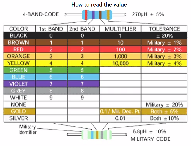
How to Read Inductor Color Code
The color bands on an inductor are a standardized parameter coding system whose primary function is to visually indicate the key electrical characteristics of the inductor through combinations of differently colored bands.
-
Four-ring inductor
Four-ring inductors have four color bands and are the most commonly used type in everyday applications.
The first two color bands represent 10 (the first band is 1, the second band is 0, combined to form 10; here, 10 is the significant digit, not the final value).
The third color band indicates the multiplier, which is the power of 10, determining the inductance level.
The fourth color band indicates the tolerance, indicating the potential deviation of the capacitor value, ensuring accuracy in various practical applications. In applications where precision is critical, even minor deviations can significantly affect the overall performance of electronic circuits.
The color ring readings for a four-ring inductor can be referenced in the figure below. For example, if the four rings are colored yellow (4) - purple (7) - red (10²) - gold (5%), the final value is: 47×10²= 4.7 nH, with a tolerance of 5%.
-
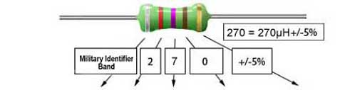
Five-ring inductor
A five-ring inductor has five color rings.
The first three color rings indicate 100 (the first ring is 1, the second ring is 0, and the third ring is 0). The five-ring capacitor has one more significant digit than the standard four-ring capacitor, resulting in higher precision.
The fourth color band indicates the multiplier, representing powers of 10.
The fifth color band indicates the tolerance.
The reading principle for five-band inductors is the same as for four-band inductors. Assuming the color bands are as shown in the figure, the reading is 270μH, with a tolerance of 5%.
Dot-Type Inductor Color Coding
On the minimal surface of surface-mount inductors, traditional color ring printing is prone to blurring or cannot accommodate the required markings. To address this issue, a dot code system has been introduced—using a combination of raised and recessed dots on the surface to ensure precise readings. Dot-type inductors typically use 1–3 dots to represent inductance value, tolerance, and dimensions. The core logic is similar to color rings but in a more compact form.
The dot code system offers extremely high space utilization efficiency, with a single dot diameter as small as 0.1 mm, making it suitable for ultra-miniature inductors. It is produced via laser engraving or special ink printing, making it resistant to oxidation and contamination, and more reliable than traditional color rings, which may fade over time. Currently, the dot code system is the optimal solution for parameter identification on small-sized surface-mount inductors, balancing the requirements of miniaturization and traceability.
-
Three-point color coding method explanation
There are two primary methods for reading dot codes: manually identifying the number and position of dots using a magnifying glass or microscope, then referencing the manufacturer's code manual to read the dot code; or utilizing AOI (automatic optical inspection), which combines high-resolution cameras with algorithms to parse the dot code automatically.
Three-point color coding represents the following from left to right:
First dot: First significant digit of inductance
Second dot: Second considerable digit of the inductance value
Third dot: Multiplier (10^n, where n corresponds to the color code)
By referencing the color ring code, assuming the decoded color ring is brown (1) - black (0) - gold (10⁻¹), the final value is: 10×10⁻¹= 1 nH, with an error margin of 5%.
Military-Spec Inductor Color Codes
Military-grade inductors typically have more complex color coding than civilian-grade color-ring inductors, which may include information such as inductance value, tolerance, temperature coefficient, and reliability rating.
In military-grade color-ring inductor coding, the five-ring standard and silver double-wide band are two special marking methods used to indicate stricter performance requirements or special applications and to explain special decoding rules and practical scenarios.
-
Five-ring standard military color ring inductors
Military-grade five-ring inductors are based on the standard four-ring configuration (numerical value + multiplier + tolerance), with an additional fifth ring to indicate temperature coefficient (TCR) or reliability rating (some special models may have six rings, with the last two rings indicating TCR and reliability rating, respectively).
Color ring meanings:
The first two rings indicate two significant digits, with color meanings identical to standard color rings.
The third ring indicates the multiplier, representing powers of 10.
The fourth ring indicates the tolerance. Most military inductors have stricter tolerances than civilian inductors, with tolerances as tight as±1%.
The fifth ring indicates the temperature coefficient (TCR), representing the stability of the inductance value with temperature (e.g., black =±250 ppm/°C, blue =±100 ppm/°C); or it may indicate the reliability grade of the inductor.
-
Special markings — silver double stripes
In military-grade color-coded inductors, a silver double-wide band (two adjacent silver bands) is a special coding format that typically represents the following special meanings:
(1) High reliability identification
The silver dual-band may indicate that the inductor meets high-reliability military standards such as MIL-PRF-15305 or MIL-PRF-83446, making it suitable for applications requiring high precision and performance. Such applications include aerospace electronics (MIL-PRF-15305 standard), satellite systems (MIL-PRF-39010/ESA standard), and missile guidance systems (MIL-PRF-83446 standard). Some dual silver ring inductors are listed on the U.S. Department of Defense Qualified Product List (QPL), ensuring long-term availability and consistent performance.
(2) Extreme environmental adaptability
The silver dual wide band indicates that the operating temperature range of this inductor has been extended to -55°C to +200°C (standard civilian inductors are only rated for -40°C to +125°C). It also indicates that this inductor has passed MIL-STD-202G vibration and shock tests, making it suitable for high-frequency vibration environments in military applications such as fighter jets and armored vehicles.
(3) Special electrical characteristics
Certain military-grade inductors with silver double-wide band markings are optimized for high-frequency circuits and offer superior high-frequency performance suitable for military applications, such as filtering and resonant circuits in radar systems.
-
Barcode reading rules comparison
|
Characteristic |
Ordinary Color Ring Inductors |
Military Color Ring Inductors |
|
Number of colour rings |
4-5 |
5-6 |
|
Tolerance accuracy |
5% (gold), 10% (silver) |
±1% (brown), ±0.5% (green), ±0.1% (purple) |
|
Temperature coefficient |
No |
Fifth ring labeling |
|
Reliability Marker |
No |
Labeling of ring 6 |
|
Special marking |
No |
Silver double wideband (for high reliability/extreme environments) |
-
Temperature Coefficient (TCR) Table (Ring 5)
|
Color |
Temperature Coefficient (ppm/°C) |
Description |
| Black | ±250 | General purpose military grade |
| Brown | ±100 | High Stability |
| Red | ±50 | Ultra-low drift (for aerospace) |
| Orange | ±15 | Precision military (e.g., missile guidance systems) |
| Yellow | ±25 | Medium Stability |
| Green | ±20 | Low Drift |
| Blue | ±10 | Very high stability (satellite communications) |
| Purple | ±5 | Top military (nuclear facilities, spacecraft) |
-
Reliability Mark (Sixth Ring)
|
Color |
Meaning |
Standard |
| Red |
MIL-PRF-39010 (Standard Military Specification) |
General Military Equipment |
| Orange |
MIL-PRF-15305 (High Reliability) |
Aerospace electronics, radar |
| Yellow |
MIL-PRF-83446 (Extreme Environment) |
Missiles, Deep Sea Equipment |
| Green |
QPL (Qualified Products List) Certification |
U.S. Department of Defense Approval |
| Blue |
Aerospace grade (NASA/ESA standards) |
Satellites, space stations |
| Purple |
Nuclear Grade (radiation hardened) |
Nuclear submarines, nuclear missiles |
-
Color ring inductors Practical applications
(1) Aerospace electronics
Standard: MIL-PRF-15305 (ring 6 orange).
Requirements: Ultra-low temperature drift (±50 ppm/°C),±0.5% tolerance.
Applications: Flight control systems (e.g., gyro stabilization circuits), satellite communication filters.
(2) Missiles and guidance systems
Standard: MIL-PRF-83446 (ring 6 yellow).
Requirements: Shock resistance, wide temperature range (-65°C ~ +150°C).
Applications: LC oscillator circuits for inertial navigation systems, radar signal processing modules.
(3) Nuclear facilities and spacecraft
Standard: Radiation resistant reinforcement (ring 6 purple).
Requirements:±5 ppm/°C temperature coefficient,±0.1% tolerance.
Applications: Nuclear reactor control circuits, power management for deep space probes.
(4) Ground military communications equipment
Standard: MIL-PRF-39010 (ring 6 red).
Requirements:±100 ppm/°C,±1% tolerance.
Applications: RF matching network for field radio, noise suppression for encryption equipment.
Color Code Inductors Units & Tolerance Letters
The value of color ring inductance is usually given in microhenries (µH), but may need to be converted to millihenries (mH), nanohygens (nH), henries (H), or even picohygens (pH) in practical applications.
-
conversion relationship
|
Unit (of measure) |
Symbol |
Conversion factors |
Typical Application Scenarios |
|
Henry |
H |
1 H = 1,000 mH |
High power supplies |
|
Millihenry |
mH |
1 mH = 1,000 μH |
Switching Power Supplies, Filter Circuits |
|
Microhenry |
μH |
1 μH = 1,000 nH |
Color ring inductor standard units, RF circuits |
|
Nanohenry |
nH |
1 nH = 1,000 pH |
High frequency microwave circuits, antenna matching |
|
Picohenry |
pH |
1 pH = 0.001 nH |
UHF (millimeter wave) research |
-
Quick conversion formula
μH÷1000→mH (e.g., 2,200μH = 2.2 mH).
μH x 1000→nH (e.g., 4.7μH = 4,700 nH).
nH x 1000→pH( e.g., 10 nH = 10,000 pH)
-
Common Alphabetic Tolerance Comparison Table
|
Alphabet Code |
Tolerance (Tolerance) |
Corresponding color ring color |
Applicable Scenarios |
|
F |
±1% |
Brown |
High-precision power supply filtering, instrumentation |
|
G |
±2% |
Red |
Communication equipment, RF matching |
|
J |
±5% |
Gold |
General-purpose circuits (most common) |
|
K |
±10% |
Silver |
Consumer electronics, non-critical circuits |
|
L |
±15% |
Colorless (some manufacturers) |
Low-cost design |
|
M |
±20% ±0.5% |
Colorless |
Power supply chokes, high current applications |
|
P |
±0.5% |
Green |
Military High Reliability |
|
W |
±0.25% |
Blue |
Aerospace, medical equipment |
|
B |
±0.1% |
Violet |
Nuclear Grade Equipment, Reference Voltage Sources |
Attention:
(1) The letter code is mostly found in the 6th ring of chip inductors or military color ring inductors, the color ring inductors are still color coded (e.g., gold=±5%), the letter code is just an auxiliary marking.
(2) Some precision chip inductors will use 3-bit code + letters, such as "68J" = 68μH±5%.
(3) A few military inductors will be labeled with a combination of letters, such as "J5" =±5% tolerance +±50 ppm/°C temperature coefficient.
Identification Tips for Color Ring Inductors
-
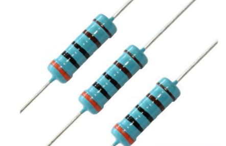
Distinguish color ring inductors from similar resistors
(1) Core differentiation criteria
|
FEATURES |
Color Ring Inductors
|
Color Ring Resistors
|
|
Main Features |
Energy storage, filtering, impedance matching |
Current limiting, voltage dividing |
|
Typical Colors |
Darkened tones (dark green, black, brown) |
Vivid color tones (red, yellow, blue) |
|
Number of Rings |
4-6 Rings (w/temperature coefficient/military coding) |
4-5 rings (a few 6 ring precision resistors) |
|
Component Shape |
Cylindrical, no pin color difference at ends |
Cylindrical shape, different color of metal caps at both ends |
|
Material Touch |
Rough surface (enameled wire or core) |
Smooth (ceramic or carbon film) |
|
Common Labeling |
Unit :μH |
Unit :Ω (e.g., "102" = 1kΩ) |
(2) Ring band logic difference
|
Ring Belt Position |
Color Ring Inductors |
Color Ring Resistors |
|
Ring 1-2 |
Effective digits |
Effective Numerals |
|
Ring 3 |
Multiplier (unit μH) |
Multiplier (in Ω) |
|
4th ring |
Tolerance |
Tolerance |
|
Ring 5 |
Temperature Coefficient (Military Inductors) |
Temperature Coefficient (Precision Resistors Only) |
|
Ring 6 |
Reliability Rating (Military) |
Rare |
(3) Physical form differentiation
|
Characteristics |
Color Ring Inductors |
Color Ring Resistors |
|
Two-end structure |
Same color on both pins (all metal or all enameled wire) |
Different color of metal caps at both ends (copper/tin plating) |
|
Surface texture |
Rough (enameled wire winding or core graininess) |
Smooth (ceramic/carbon film uniform coating) |
|
Dimensional Proportions |
Slim Type |
Short and thick type |
(4) Other auxiliary judgment methods
Multimeter detection: The resistance value is stable after the resistor is energized. At the same time, the resistance value of the inductor is close to 0Ω(DC short circuit). Therefore, an LCR meter is needed to measure the inductance.
Circuit Location: Inductors are commonly used in power supply filtering (DC-DC) and RF circuits (LC oscillation), while resistors are widely used for voltage dividing, current limiting, and pull-up/pull-down.
-
Common code reading errors and solutions
|
Common Errors |
Solution |
|
Color ring color misjudgment |
Observe under natural light or white LED, and use a magnifying glass to assist in distinguishing the difference in hue, or use a digital camera in macro mode to compare with the standard color code table after shooting. |
|
Color ring direction reading error, reverse reading or ignoring the wide ring/spacing tips |
First observe the distribution of color rings, usually the first ring is close to one end of the component, and the width of the first ring may be slightly wider or less spaced from the pins; if you can't confirm, give priority to the end of the color ring group without gold/silver as the starting ring (because gold/silver ring usually represents the tolerance/multiplication, and seldom appears in the first place). If you are still in doubt, you need to verify the logic of the direction by measuring the approximate value with a multimeter or consulting the device specification. |
|
Confusing multiplier units or ignoring special multipliers (e.g., the double silver rings of military inductors indicate 0.01). |
Clarify that the base unit of color ring inductance is μH, the multiplication ring only adjusts the magnitude, and if nH unit is needed, it needs to be converted manually. |
|
Ignoring the tolerance and temperature coefficient |
For all color ring components first unified count of the number of rings, if more than 4 rings, need to be resolved according to military rules: the fifth ring for the temperature coefficient, the sixth ring for the reliability level (such as orange = MIL-PRF-15305). For high reliability scenarios, the MIL-HDBK-199 manual must be checked to confirm the meaning of the special code. |
Conclusion & Best Practices
Suggest to readers how to use the color code to read accurate parameters in actual selection or repair.
To accurately read the parameters of color-coded inductors in actual selection or maintenance, the following systematic steps can be followed.
First, observe the inductor under sufficient natural light or white LEDs, and use a magnifying glass to help identify the color ring to ensure accurate color judgments (e.g., distinguish between brown and red, blue and purple).
Second, confirm the starting direction of the color ring. Usually, the first ring is near the end of the component or the widest ring. If there is a gold or silver ring, it is preferred to exclude it as the first ring.
Next, record the colors of the rings in order, with the first two rings representing significant digits, the third ring being the multiplier (base unit isμH), the fourth ring indicating the tolerance (e.g.,±5% for gold), the fifth ring (if any) labeled with the temperature coefficient, and the sixth ring (for military models) possibly representing the reliability class.
Then, the standard color code table will be converted to numerical values, and the inductance value (such as brown - black - red - gold corresponds to 10×100μH±5% = 1mH±5%)
Finally, use the LCR meter to verify the readings. If the deviation exceeds the tolerance range, it is necessary to re-verify the ring sequence or consider the aging factor of the components. Meanwhile, for military or special high-precision inductors, it is also required to consult the MIL-HDBK-199 manual to confirm the special coding rules, to ensure that the key parameters (e.g., temperature coefficient of±100ppm/°C) are in line with circuit requirements.
The whole process needs to be combined with visual judgment, tool measurements, and document cross-referencing to form a closed-loop verification to avoid selection errors or maintenance mistakes.
FAQ
How to read inductor code?
(1) Starting ring determination: the first ring is usually near the inductor end, or the widest ring band.
(2) Ring number classification
|
4 rings |
First two digits + Multiplier + Tolerance |
|
5 rings |
First three significant digits + multiplier + tolerance (precision inductors) |
|
6 rings |
Military specification, may include temperature coefficient (ring 5) and reliability rating (ring 6) |
(1) Query the color ring color corresponding to the number
(2) Calculate the resistance value, high-frequency circuits (such as RF) commonly used nH, power supply circuits moreμH/mH, if necessary, you can do unit conversion.
What is the 5 color band inductor?
Five-color ring inductors are a kind of fixed inductors with parameters marked by five colored rings. The coding rules are extended based on the traditional four rings (numerical value, multiplication, and tolerance), and the fifth ring is specially used to indicate the temperature coefficient of resistance (TCR) or special-purpose codes, which are commonly used in high-precision or military-specification (MIL-Spec) inductors.
The specific interpretation is as follows:
The first and second rings represent significant digits
The third ring is the multiplier (base unit is microhenryμH)
The fourth ring labels the tolerance (e.g., gold±5%)
The fifth ring defines the temperature stability (e.g., blue =±100ppm/°C) or the military reliability class (e.g., orange = MIL-PRF-15305).
For example, the color ring sequence "Brown-Black-Red-Gold-Blue" indicates 10 x 100μH = 1mH±5%, with a temperature coefficient of±100ppm/°C. These inductors are suitable for avionics or industrial equipment that needs to withstand temperature changes.
These inductors are usually made of magnetic cores or alloy materials with rough surfaces and dense color rings. They need to be verified by an LCR table and combined with MIL-HDBK-199 and other military standard manuals to check the meaning of the special code and ensure the accuracy of the parameters.
Recommended Reading:
Zero-Ohm Resistor: A Comprehensive Guide to Definition, Applications, and Design Techniques
Understanding DC Motor Components: A Comprehensive Guide