Terminal Block Connectors Explained: A Complete Guide to Types, Brands & Applications
What is a Terminal Block?
Terminal blocks are modular insulated cable connectors available in various types to suit different electrical applications, including screw-type, spring-clamp, and push-in styles. Regardless of type, all terminal blocks comprise three primary components: an insulating body, a conductive busbar, and a clamping mechanism. The insulating body is typically made from high-strength, heat-resistant, and insulating materials such as thermoplastics or thermosetting resins. The conductive busbar, composed of highly conductive metals like copper, brass, or their alloys, provides an electrical pathway between wires, ensuring minimal resistance and heat generation during current transmission. The clamping mechanism securely fastens the cables to the busbar, forming a stable, low-resistance connection within the terminal and preventing cable loosening due to vibration or mechanical stress.
In industrial electronics applications, wiring terminals offer a reliable, tidy, and secure wiring solution that easily accommodates system expansion needs. Furthermore, their cost-effectiveness and compatibility with diverse components make them an ideal choice for power, signal, and data connections in harsh environments.
Why Use Terminal Blocks Instead of Soldering or Tape?
Terminal blocks provide a reversible, flexible connection method, particularly suited for industrial environments requiring frequent modifications, maintenance, or high-volume production. The selection of terminal blocks is based on a series of trade-offs, primarily involving maintainability, reliability, and safety.
-
Maintainability
Terminal blocks allow a single wire to be connected or disconnected in seconds using just a screwdriver. This convenience saves countless hours of labor during product prototyping, testing, and debugging phases, or in industrial equipment requiring frequent circuit changes.
When system faults occur, individual wires can be easily disconnected from terminals for measurement or isolation without touching other circuits. If a component fails, it can be swiftly removed from the terminal and replaced without requiring a soldering iron, greatly simplifying maintenance procedures.
-
Reliability
(1) Vibration Resistance and Anti-Loosening Properties
High-quality terminal blocks (such as spring-clamp types) are engineered to withstand vibration and shock. Their clamping force is precisely calculated to prevent wire loosening due to mechanical stress, offering a perfect solution to address issues like screw loosening or solder joint fatigue cracking. This is critical in sectors such as rail transportation, heavy machinery, and aerospace.
(2) Reduce human error
The installation process for terminal blocks is standardized and straightforward, with cables arranged neatly and circuit layouts clearly defined, significantly reducing the risk of poor connections caused by human error. In contrast, soldering quality is highly dependent on the operator's skill, temperature, and materials. A "cold solder joint" may appear fine, but it is actually a high-resistance fault point.
(3) Stable contact resistance
The copper alloy conductor and clamping mechanism inside the terminal ensure a large contact area and constant pressure, providing a stable, low-resistance connection that minimizes energy loss and heat generation.
-
Safety
Terminal blocks can be neatly mounted on rails to achieve a modular layout, optimizing space utilization while facilitating airflow and heat dissipation to prevent safety hazards caused by high temperatures. Additionally, the insulators of these terminals are typically made from flame-retardant materials such as nylon PA66, completely isolating live parts to prevent accidental electric shocks and short circuits. Many terminals also feature finger protection, meeting stringent safety standards.
Common Characteristics of Terminal Blocks
-
Structural Composition
(1) Insulator
This component is typically manufactured from high-performance engineering plastics such as nylon (PA66) and polycarbonate (PC). These materials offer excellent insulation properties, mechanical strength, high-temperature resistance, flame retardancy (e.g., UL94 V-0 certified), and aging resistance.
This serves as the terminal's skeleton and protective layer, primarily preventing short circuits between conductors at different potentials to ensure personal safety and proper equipment operation. It provides mechanical support and protection for internal conductors and connection points, shielding them from external impacts, dust, moisture, and other adverse effects. The insulator is typically marked with wiring identifiers and rated current/voltage values, and features rail slots and mounting holes for easy identification and installation.
(2) Current-carrying element
Typically made from highly conductive metals such as electrolytic copper. To enhance corrosion resistance and solderability, the surface undergoes plating treatment. The most common plating is tin plating, which offers excellent conductivity, oxidation resistance, and lower cost. In harsh environments, nickel-plated conductive bodies are frequently used, as they provide higher hardness, superior wear resistance, and better corrosion resistance.
The current-carrying body serves as the "heart" of the terminal, responsible for bearing and transmitting electrical current. Its structural design determines the terminal's rated current capacity. As the most technically sophisticated component within the entire terminal assembly, it directly dictates the terminal's current-carrying capability and reliability.
(3) Clamping device
The clamping mechanism is the terminal's muscle, responsible for generating and maintaining a reliable clamping force on the wire. Its performance is critical, ensuring low and long-term stable contact resistance to prevent wire loosening, overheating, or even disconnection.
-
Core General Characteristics and Performance Parameters
(1) Electrical Characteristics
- Rated voltage
The maximum voltage at which the terminal can operate safely over the long term, such as 250V, 600V, etc.
- Rated current
This is the core parameter for selection, representing the maximum current the terminal can sustain over the long term. It is typically related to the conductor cross-sectional area and material, such as 10A, 25A, 100A, etc.
- Contact resistance
The resistance at the contact point between the clamping device and the wire. Its resistance value must be extremely low and stable; excessive resistance can cause overheating and energy loss, making it a critical factor in determining terminal quality.
- Compressive strength
A key indicator of safety, representing the ability of an insulator to withstand short-term high voltage between conductors at different potentials without breakdown.
- Insulation resistance
The ability of insulating materials to resist current leakage; the higher the value, the better.
(2) Mechanical Properties
- Wiring capacity
Specify the range and type of wire cross-sectional area that can be reliably connected.
- Clamping force
The force exerted by the clamping device on the conductor. Sufficient clamping force ensures low contact resistance.
- Mechanical life
The number of times a terminal (especially spring-loaded) can be reconnected.
- Vibration resistance
In critical sectors such as rail transit and heavy machinery, terminals must withstand prolonged vibration without loosening. Spring-loaded connectors demonstrate distinct advantages in this regard.
(3) Environmental Characteristics
- Operating temperature range
The operating temperature range for terminals, as well as the performance of insulating and metallic materials, are all affected by temperature.
- Protection Rating
For terminals used outdoors or in humid environments, a high protection rating (such as IP65 or IP67) is required to prevent dust and water ingress.
- Corrosion resistance
Ensure reliability in harsh environments such as humidity, salt spray, and chemical gases through the selection of plating layers and materials.
- Flame Retardant Rating
Insulation materials must be flame-retardant to prevent fire spread and are typically required to meet UL94 V-0 certification.
(4) Security and Authentication
High-quality terminal blocks typically obtain certifications from internationally recognized authorities, ensuring these products comply with safety and performance standards for specific regions, such as:
|
UL (America) |
 |
|
cUL (Canada) |
 |
|
CE (Europe) |
 |
|
TÜV (Germany) |
 |
|
CCC (China) |
 |
Types of Terminal Blocks by Function
(1) Universal Terminal Block
This is the most common and fundamental type of terminal block, primarily used for simple wire connections and busbar connections. Featuring a straightforward structure, it provides a secure and reliable electrical connection point that is easy to install, maintain, and test, though it typically lacks additional electronic functions. Main types include screw terminals and spring-loaded terminals.
(2) Fuse Terminal Block
This is an integrated component combining a terminal block and fuse holder for overcurrent protection in circuits. Its integrated design provides a convenient, centralized overcurrent protection point for circuits. When the current exceeds the rated value, the internal fuse melts, thereby interrupting the circuit and protecting downstream equipment.
(3) Thermocouple Terminal Block
This is a specialized terminal designed specifically for connecting thermocouple temperature sensors. It connects thermocouple wires and ensures the accuracy of temperature measurement signals. Operating based on the Seebeck effect, the minute voltage it generates is highly sensitive to the materials at the connection points.
(4) Ground Terminal Block
This is a specialized safety terminal block designed exclusively for connecting ground wires. It provides a centralized, reliable, and clearly labeled connection point for the protective earth (PE) conductor of equipment or systems, ensuring personal safety and proper equipment operation.
In addition to the types mentioned above, numerous terminals integrate specific electronic or protective functions.
(1) Surge Protection Terminal Block
Surge suppression components, such as internally integrated metal-oxide varistors (MOVs) or gas discharge tubes, rapidly discharge surge currents to ground when voltage exceeds the threshold, protecting downstream equipment from transient overvoltage (surge) damage caused by lightning strikes or switching operations.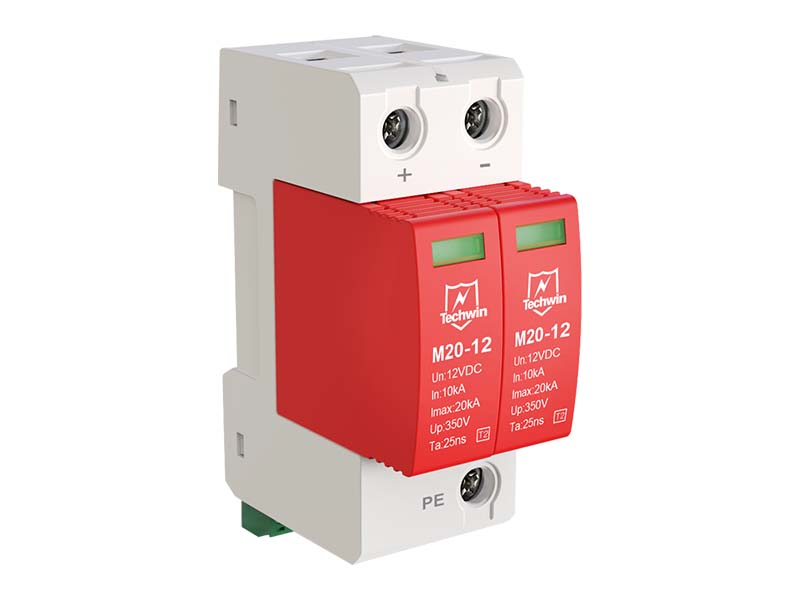
(2) Diode Terminal Block
Integrate the diode within the terminal to save space and simplify installation, enabling logic isolation in circuits (such as preventing signal backflow), rectification, or freewheeling.
Types of Terminal Blocks by Connection Method
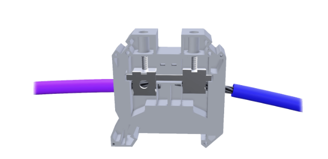
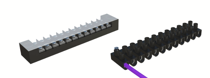
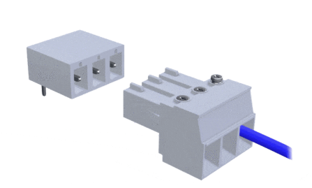
(1) Screw-type terminal block
The most commonly used connection method is the screw-type terminal block. This type of terminal secures wires with screws and features two common structures.
The first is direct screw compression, where the screw presses directly onto the wire. However, excessive tightening may damage the wire, leading to poor connections or even safety hazards. A modern, commonly used design involves the screw pushing an independent metal clamping plate to grip the wire. This clamping plate provides a larger contact area and employs translational rather than rotational motion. This effectively prevents wire breakage or damage and offers superior vibration resistance.
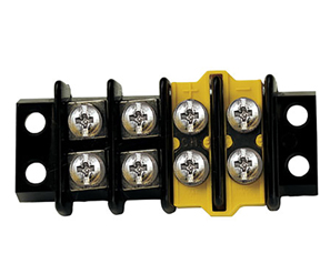
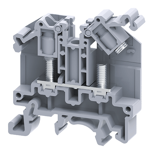
(2) Barrier-type terminal blocks / European connectors
Barrier-type terminal blocks closely resemble screw-type terminal blocks, both utilizing screws to clamp wires. Commonly referred to as barrier-type terminal blocks, they are also known as European connectors due to their widespread adoption in Europe.
Depending on application scenarios and environmental requirements, barrier terminal strips can be equipped with compact covers to protect wiring. Similar to screw-type terminals, stripping wires to the correct length is critical; otherwise, the screw clamp may fail to make contact with the conductor body. They feature high safety and high mechanical strength.
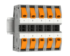
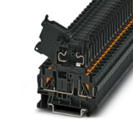
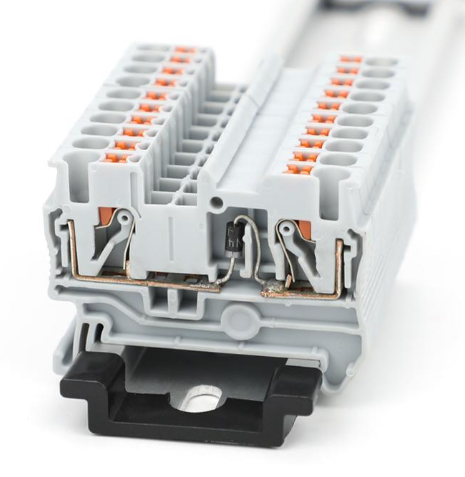
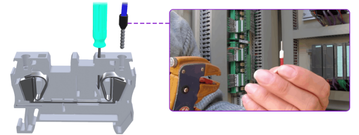
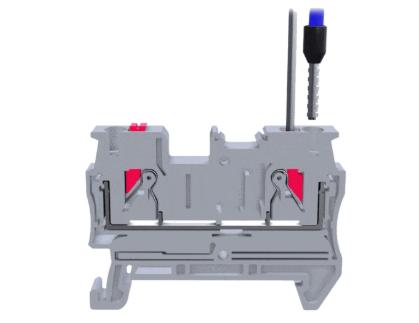
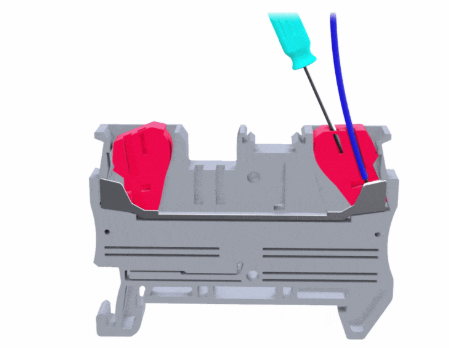
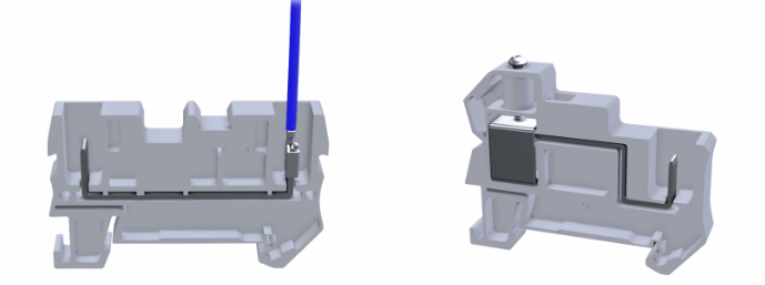
(3) Spring-loaded Terminal Block / Spring-loaded Connection
Another standard wiring method is the spring-loaded terminal block, whose core component is a high-quality corrosion-resistant spring.
Insert the wire to complete the connection. Most such terminal blocks require wires to be fitted with ferrules before insertion.
Ferrules or wires can be installed or removed by engaging the spring release mechanism. Some models feature proprietary spring release mechanisms, but most require a small screwdriver for operation.
(4) Push-in/Crimp Terminal
Crimp-type or push-in terminals are becoming increasingly popular. Similar to spring-loaded terminals, "crimp-type" terminals typically require wires to be fitted with ferrules. Connection is achieved simply by inserting the wire, with an internal self-locking spring mechanism allowing insertion while preventing the wire from being pulled out.
The most significant difference between spring-loaded and push-in terminals lies in the wire release mechanism. Push-in terminals can integrate the release device directly adjacent to the wire insertion point.
(5) IDC Terminal Block
This is a crimp-free connection technology designed explicitly for ribbon cables or flat cables. Initially applied in the telecommunications industry, it typically appears in rows and is suitable for large-scale automated production. It requires specialized tools or crimping machines for crimping, and insertion does not require stripping the cable insulation. Two sharp blades inside the terminal cut through the insulation and make contact with the internal metal conductor, forming an airtight connection.
When first introduced, this terminal type was better suited for solid wires than stranded wires. However, IDC products suitable for both wire types have now been developed.
(6) Pluggable Terminal Block
Pluggable terminal blocks feature plug interfaces that connect to sockets, with their bases secured to circuit boards. Strictly speaking, this is not an independent "electrical connection" method but rather a mechanical connection solution.
Wires are inserted and clamped in place by screws. The wire connection employs a plug-and-socket configuration. Such terminal blocks are suitable for applications requiring quick disconnections, such as circuit maintenance and testing.
(7) Surface-mount connector terminal
On blade connectors, wires are inserted into the blade contacts. Depending on the connector type, wires can be connected via crimping or soldering.
Blade connectors also offer a dual-port design: one side features blade connections, while the other utilizes screw-clamp connections.
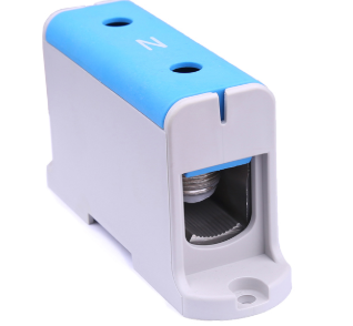
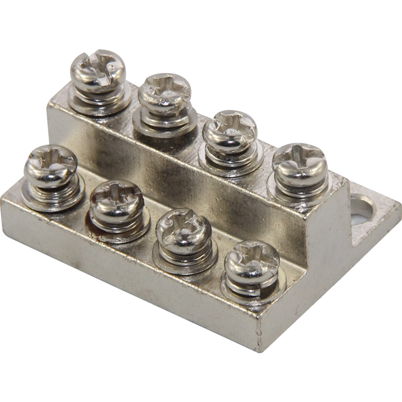
(8) Stud-type terminal block
These terminal blocks feature threaded metal studs mounted on insulated bases. Ring or fork-shaped terminals are secured onto the central metal stud using nuts and washers. Their simple construction enables them to withstand extremely high currents and voltages, providing a very secure connection. However, they occupy significant space and require additional nuts and tools for installation. They are suitable for high-power inverters, power supply equipment, transformers, and similar applications.
Mounting & Structural Considerations
-
Installation Method Selection
The two primary installation methods are as follows:
|
Installation Method |
Definition |
Installation Method |
Advantages |
Disadvantages |
Applicable Scenarios |
|
DIN Rail Mounting |
A standardized metal rail with a standardized cross-sectional shape, typically installed in rows on the back panel or mounting strip of a control cabinet, represents the most mainstream and universal mounting method currently available. |
The terminal block features a specially designed slot and spring-loaded latch at its base. During installation, first snap one end of the terminal into the upper edge of the rail, then press down on the other end until the latch snaps into the lower edge of the rail. To remove, use a screwdriver or your finger to press down on the latch, allowing the terminal to slide off the rail. |
1. High flexibility, allowing easy addition, removal, or rearrangement of terminals; 2. Supports high-density installation; 3. Standardized, with nearly all industrial terminals, circuit breakers, PLCs, power supplies, and other equipment supporting DIN rail mounting, ensuring excellent compatibility; 4. Easy maintenance enables individual terminal removal without affecting the entire circuit. |
1. Requires installing DIN rails first, adding an extra step. 2. For extremely heavy or high-current terminals, additional support may be needed. |
Almost all industrial environments, such as PLC control cabinets, distribution boxes, automation equipment, and instrumentation enclosures, are equipped with these components. |
|
Panel fixed installation |
Also known as "direct-mount" or "screw-retaining" installation, this method involves directly securing the terminal block to a panel or backplane. |
Terminal blocks feature mounting holes either on the block itself or at both ends. During installation, position the terminal block in the designated location, thread screws through the mounting holes, and secure it directly to the panel. Some designs feature multiple terminals sharing a single long mounting strip. |
1. High stability, with superior vibration and physical impact resistance compared to DIN rail mounting; 2. Eliminates the need for additional rails, saving costs and steps associated with purchasing and installing DIN rails; 3. More cost-effective for simple applications. |
1. Poor flexibility: Once installed, it is difficult to add or move terminals. Layout changes require re-drilling holes in the panel. 2. Each terminal or terminal group requires individual screw fastening, making installation more time-consuming. 3. Low installation density. |
1. Permanently installed equipment with fixed layouts; 2. Applications demanding exceptional vibration resistance, such as rail transit, marine vessels, and heavy machinery; 3. Terminals for extremely high currents, which are both heavy and bulky, making direct panel mounting more reliable. |
-
Installation Level Selection
|
Hierarchy |
Features |
Applicable |
|
Single-layer terminal block |
The most basic and standard configuration. All connection points (input and output) are located on the same horizontal plane, featuring a simple structure, the lowest cost, and intuitive wiring. |
Basic functions such as simple power distribution and signal transmission. This is the most widely used type. |
|
Double-layer terminal block |
Within the same terminal block width, two rows of wiring channels are stacked vertically, doubling the wiring density over the same rail length. This is its most significant advantage. |
Applications requiring high-density wiring include compact PLC cabinets and interfaces for distributed I/O modules. |
|
Three-Tier Terminal Block |
It represents the pinnacle of compact design, enabling numerous connections on extremely short rails with exceptional space efficiency, allowing for functional integration. |
For applications with extremely demanding space requirements, such as compact servo drives, valve island interfaces, and miniature control cabinets. |
|
Multi-level/Multi-tier Terminal Block |
More commonly, it refers to achieving functional expansion by increasing "height" rather than "planar density," meaning stacking various functional modules—such as fuse layers and switch layers—on top of the base wiring layer. |
Applications that require integrating connection functions with circuit protection/control/indication functions. Offers significant flexibility and functionality, but at a higher cost. |
Industrial Applications
-
Power Distribution in the Control Panel
This represents the most classic and widespread application scenario for terminal blocks, where they serve as both the framework and the hub. This enhances the flexibility of circuit modifications and improves circuit reliability.
(1) Main Power Supply Connection and Distribution
Industrial three-phase power (such as L1, L2, L3, N, PE) is first connected to the power terminal block. Through jumpers or comb strips, electrical power is efficiently and neatly distributed to multiple branch circuits, such as supplying different circuit breakers, contactors, variable frequency drives, and servo drives.
(2) Protective Grounding
The dedicated grounding terminal strip (PE terminal) provides a unified, reliable grounding reference point and safety protection path for the entire system, ensuring personnel and equipment safety.
(3) Fuse Protection
Fuse terminals integrate fuses into the connection path, providing overcurrent protection for sensitive circuits such as control circuits and PLC output points.
(4) Quarantine and Testing
Circuit breaker terminals or terminals with test functions enable the isolation, testing, and maintenance of individual circuits without interrupting the entire system, significantly enhancing convenience and safety.
-
Signal Transmission and Measurement Systems
In industrial environments, numerous sensors and actuators transmit either weak analog signals or high-speed digital signals, which are highly susceptible to interference. To address this, specialized signal terminals have been designed.
(1) Sensor Link
Proximity switches, photoelectric sensors, encoders, and similar devices are typically pre-wired to terminal blocks with M8/M12 connectors for quick plug-and-play installation and replacement. For PT100 thermistors or thermocouples, dedicated temperature measurement terminals are provided, often employing spring-clamp technology to prevent contact resistance from affecting measurement accuracy.
(2) Analog Signal Transmission
Analog I/O signals for connecting devices such as pressure transmitters (4-20mA) and level gauges. Shielded terminals are critical, as their built-in metal claws or shielding plates effectively ground the cable shielding layer, preventing electromagnetic interference (EMI) and radio frequency interference (RFI) from compromising signal integrity.
(3) Data Bus System
Modern automation systems commonly employ fieldbus technologies (such as PROFIBUS and DeviceNet) and industrial Ethernet (such as PROFINET and EtherNet/IP). Bus terminals are used to connect these network cables, ensuring impedance matching and reliable communication.
-
Typical Applications in Industrial Automation Systems
(1) Motor Control Center
Within cabinets housing soft starters, variable frequency drives, and other equipment used to control motor start-stop operations, extensive wiring employs power terminals, fuse terminals, and relay terminals.
(2) Human-machine interface
The buttons, switches, and indicator lights on touchscreens (HMI), consoles, and control panels are all connected to terminal blocks, ensuring a neat and standardized wiring configuration.
(3) Safety System
Safety circuits such as safety relays, emergency stop buttons, and safety light curtains require the use of safety terminals with vivid colors (typically yellow). These terminals are usually equipped with forced-guidance contacts or redundant designs to ensure functional safety levels (such as SIL or PL).
How to Choose the Right Terminal Block
-
Current and Voltage Parameters
(1) Current-Related Selection Principles
When selecting terminals, calculate the maximum continuous current for the application based on the load power and allow a sufficient safety margin. It is generally recommended to choose specifications 20%-50% higher than the calculated current.
Since terminal ratings are defined at specific ambient temperatures (typically 20°C or 40°C), their current-carrying capacity decreases at higher operating temperatures. Selection must reference the derating curve provided by the manufacturer. For example, a terminal rated for 100A may only safely carry 70A at 80°C. During high-density installations, adjacent terminals may affect each other's heat dissipation, potentially requiring derating.
(2) Voltage-Related Selection Principles
The selected rated voltage must exceed the highest voltage that may occur in the system. For high-voltage applications (e.g., above 380 VAC or above 1000 V DC), special attention must be paid to creepage distance and electrical clearance. In humid or dusty environments, a greater creepage distance is required to prevent arcing and short circuits.
-
Wire Specifications and Handling
Ensuring perfect matching between terminals and wires is key to guaranteeing low contact resistance and mechanical strength.
(1) Compatible wire diameter range
Each terminal has a clearly marked applicable wire cross-sectional area range. It is strictly prohibited to use wires exceeding this range. Wires that are too thin may have insufficient contact area, potentially preventing proper crimping and resulting in excessive contact resistance and overheating. Wires that are too thick may fail to fully insert into the terminal cavity or damage the terminal's crimping mechanism or insulating sleeve.
(2) Wire Type
Most universal terminals are compatible with flexible wires, while some terminals (such as specific insulation displacement connectors, IDCs) are explicitly designed for rigid cables. Always verify compatibility before wiring. Using terminal sleeves during wiring helps prevent risks such as short circuits and corrosion.
-
Environmental factors (temperature, dustproof and waterproof, vibration)
(1) Temperature
The materials and insulators of terminals have their own temperature limits. For instance, standard nylon (PA66) insulators have a long-term operating temperature range of approximately 105°C to 120°C. High-temperature plastics (such as PPS) or ceramics can withstand temperatures exceeding 150°C.
In high-temperature environments, terminals with metal components plated with tin, nickel, or stainless steel, and insulators made of high-temperature plastics should be selected. In low-temperature environments (e.g., -40°C), attention must be paid to whether the plastic may become brittle.
(2) Protection Rating
The IP code indicates the level of protection against dust and water ingress.
For example, IP20 is commonly used in dry, clean environments such as inside electrical cabinets; IP65/67 is used in applications where exposure to water, oil contamination, or high-pressure washing is possible (e.g., food machinery, outdoor equipment, vehicles). These terminals typically feature sealing rings (at the cable entry point and between the terminal and the mounting surface of the rail) and sealing caps.
(3) Vibration and Shock
In applications such as rail transit, heavy machinery, and wind power, vibration is the primary cause of connection loosening. It is recommended to select spring-loaded terminals or screw connections with locking mechanisms.
-
Modular expansion capability
(1) Base Type
- Single-unit type: Individual terminals that achieve electrical connections via rail slot plates, offering high flexibility.
- Bridge-type: Multiple circuits are integrated within a single plastic base. Plug-in bridge connectors enable rapid parallel connection of multiple circuits, significantly reducing installation and wiring time.
(2) Marking and Identification
Clear labeling is essential for installation and maintenance. Select a terminal system that provides labeling areas (handwritten), printable label strips, or electronic tags.
FAQ
-
What is a terminal block connector?
terminal block connectors serve as universal interface components for electrical connections. Featuring multiple parallel terminals on an insulated base, they enable the safe and organized centralized connection and distribution of various wires. Widely used in distribution boxes, control cabinets, and similar equipment, they facilitate the installation, maintenance, and testing of circuits.
-
What are the different types of terminal connectors?
Terminal connectors are primarily categorized into terminal blocks, connectors (such as circular, rectangular, PCB terminals, and RF connectors), as well as junction boxes and terminal sockets. These components facilitate electrical connections, circuit isolation, and signal transmission.
-
What is the difference between terminal blocks and Wago?
Terminal blocks are a broad generic term referring to all components used for electrical connections and the separation and joining of wires. They come in numerous varieties, including rail-mounted, panel-mounted, and plug-in types.
Wago, a German brand, is a global leader and innovator in spring-cage connection technology. Renowned for its easy-to-operate, highly reliable, and maintenance-free terminal block products, the term "Wago terminal" typically refers specifically to terminals manufactured by this brand that utilize its unique spring-cage pressure technology.
-
What is a 3-way terminal block?
A three-terminal connector is an electrical connection component typically featuring three independent connection points (or "ports"). It enables the reliable connection of three wires or facilitates branch and busbar functions within circuits. Their structure generally includes an insulated housing, a metal conductor, and fasteners (such as screws or spring clips). These components mechanically secure the wires to ensure low resistance and stable electrical contact. Widely used in distribution boxes, industrial control cabinets, home appliances, and lighting systems, they simplify wiring, enhance safety, and facilitate maintenance.
Manufacturer/Product Recommendations
Founded in Germany in 1923, this globally renowned enterprise began as a manufacturer of industrial connectors. Today, it has evolved into a world leader in electrical interconnects, electronic interfaces, and industrial automation technology, celebrated for its high quality, durability, and reliability across an extensive product portfolio. The ST 2.5-TWIN series model 3031241 represents its classic design, featuring a pull-back spring connection.
Amphenol, an American company founded in 1932, ranks among the world's leading connector manufacturers. The company designs, manufactures, and markets electrical, electronic, and fiber optic connectors, coaxial and flat ribbon cables, and interconnect systems. Its products are widely used across automotive, broadband communications, commercial aviation, defense, industrial, and other sectors. Amphenol enjoys a high reputation in the industry for its innovative technologies and extensive product portfolio. Amphenol's QT series terminal blocks utilize IDC technology to enhance wiring efficiency by 70% while delivering long-term reliability.
The company offers a wide range of connectivity and sensor solutions for applications across electric vehicles, aerospace, digital factories, smart homes, healthcare, and more. With a strong focus on innovation, it holds over 15,000 granted or pending patents. TE's push-in PCB terminal blocks feature a push-in clamping termination method that reduces wiring time, thereby lowering labor costs.