
Experience in Solving Audio Signal Ground Noise Based on the BA3121
In designs involving embedded products, robots, and similar applications, audio amplifier design is sometimes indispensable. Our requirements for audio are not high; as long as the volume is sufficient and the sound is clear, clean, and free of noise, it will suffice. After all, we are not creating professional audio systems, so we do not need high fidelity, 4D surround sound, or balanced highs and lows.
What is a ground loop?
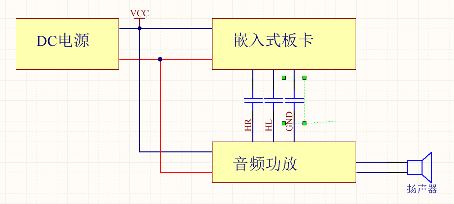
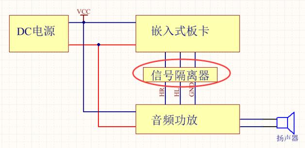
As shown in the diagram below, the embedded board and the amplifier use the same power supply. The audio signal is output from the embedded board to the audio amplifier via a 3.5MM interface.

As indicated by the red markings in the above diagram, the ground loop formed between the ground circuit and the 3.5MM audio signal can result in a ground loop issue. If the circuits on both sides of the 3.5MM jack are not specially treated, you may hear a persistent "buzz..." noise from the amplifier speaker. This noise will persist and increase as the volume of your embedded board increases, which is caused by the common ground noise.
This noise is unacceptable. Could breaking this loop resolve the issue? The first solutions that come to mind are capacitor isolation or disconnecting the ground wire, as illustrated in the diagram below.
However, after my practical tests, the final conclusion was that these methods are all ineffective.
Solution
After consulting various materials, examining other online cases, and seeking advice from professional audio amplifier design engineers, I have summarized the following: there are three ways to resolve this ground loop interference—power isolation, audio signal isolation, and signal ground separation.
Method One: Power Isolation
The circuit design topology is as follows:
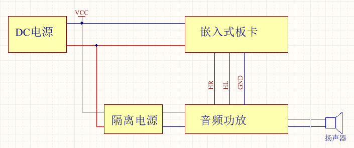
The power supply for the embedded board is provided by a DC power source, while the audio amplifier is powered by a DC-DC isolated power supply. This design effectively separates the ground of the amplifier from that of the embedded board, preventing the formation of ground loops and thereby eliminating ground loop noise.
It is crucial to use an isolated power supply; a non-isolated power supply will not achieve the desired effect.
When I disassembled a small boat robot, I discovered that it employed this method of power isolation for its audio design. The actual component setup is shown in the image below.
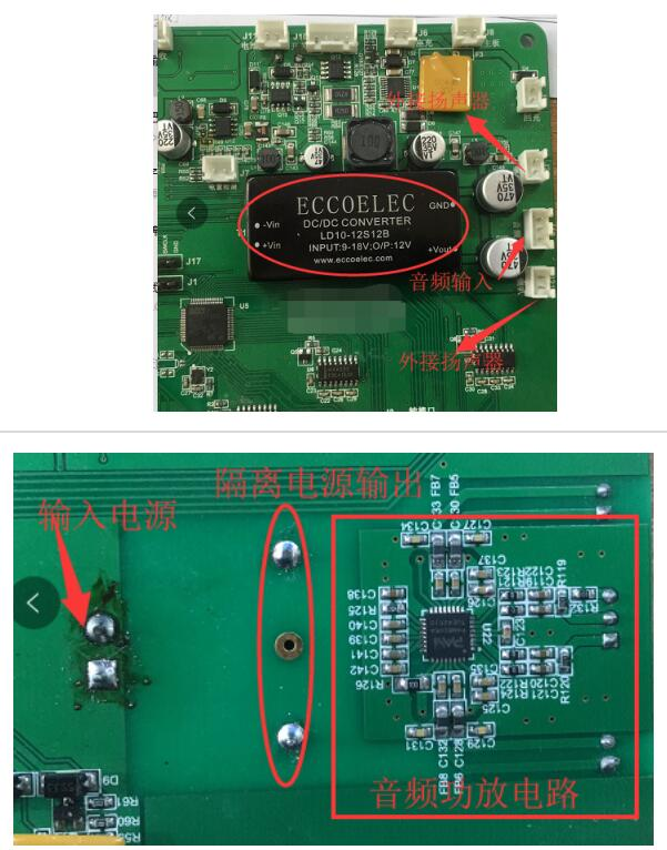
Judging from the silk-screen printing, the power supply employs a 10W 12V to 12V isolated power converter, and the audio system uses the PAM8006scheme, which is a class D digital amplifier with 15Wx2 dual-channel output for 8-ohm speakers.
Method Two: Audio Signal Isolation
Audio signal isolation typically occurs at the front end of the amplifier (i.e., the input signal) to isolate the audio signal.
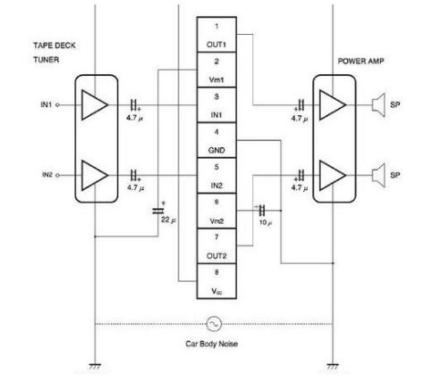
Below is an example of an audio isolator that I found online. Its internal circuit uses coupling inductors, and the schematic diagram is as follows:
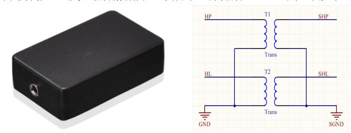
In actual use, you simply need to add this isolator to the 3.5mm audio input signal.
The internal structure of this isolator is quite simple; it essentially consists of coupling inductors (one for each of the left and right channels). It is also fairly convenient to use. The only drawback is its relatively large size, though one could integrate these coupling inductors directly onto the circuit board.
Method Three: Segmentation of Audio Signal Ground
If neither isolated power supplies nor signal isolators are used, employing a ring ground method to set up the audio solution can potentially address the noise caused by ground loops.
The answer is affirmative, but it requires significant expertise and advanced circuit design skills.
"Segmentation of Audio Signal Ground" is a term I coined myself, and it might not sound very professional. The design principle involves ensuring that the embedded boards provide a clean audio signal, free from excessive noise. The basic principle is as follows:
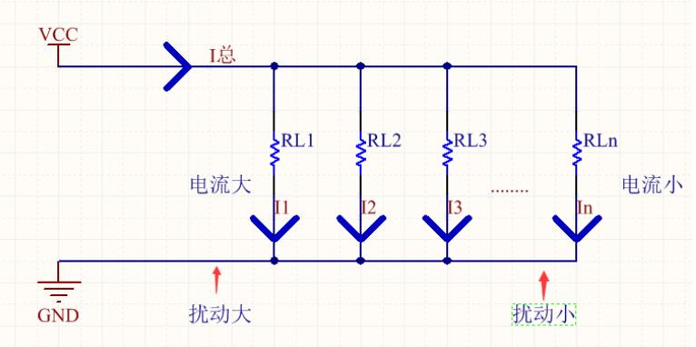
The image above illustrates the design concept for an embedded board (audio source). Generally speaking, embedded boards feature numerous power-consuming components such as display screens, CPUs, memory, and audio systems. These components can be viewed as individual loads through which current flows.
All currents flow from the positive to the negative terminal of the power supply. Hence, it is essential to design the power supply and grounding of the embedded board rationally. As shown in the image, the total input current, denoted as I_total, flows towards the loads: RL1, RL2, ..., RLn, each generating corresponding currents I1, I2, ..., In.
In designing an embedded board, high-current loads should be positioned near the power supply port, followed by medium-current loads, and finally low-current loads. The 3.5mm audio output carries a very small current, represented here by RLn, with negligible current flow. The 3.5mm audio signal and ground are output from this point.
This design ensures that the influence of high-current devices on the ground does not affect the subsequent stages of the power ground.
How can such a design be realized? It involves the segmentation of the ground plane. By effectively dividing the ground plane, the current flow in the power ground can be controlled (it is crucial not to use a fully copper-filled method to achieve ground plane design). At the far end, due to the minimal current, the impact on the power supply is also minimal, resulting in a clean audio signal output.
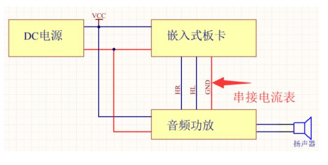
How can one determine if an audio signal is clean?
It's quite simple: connect an ammeter in series with the audio signal. If there is current displayed on the ammeter, then the signal is not a perfect audio signal.
Practical Design
Incorporating the methods mentioned above, how should I choose for my project?
First, considering the isolated power supply option: my project requires at least a 20W isolated power supply. The cost for just one isolated power supply is around 60, which seems rather uneconomical.
Second, the signal isolation option: While signal isolators are not expensive, they tend to be quite bulky. If I were to design a coupling inductor onto the circuit board, it’s challenging to find a suitable inductor readily.
I have eliminated the third option outright since the primary source of noise in my project is the board itself, which is a third-party component that I cannot modify.
Thus, it becomes clear that only options one and two remain viable.
In daily life, automobiles are equipped with numerous electronic devices inside, yet they typically rely on a single power source (battery or alternator, with only one operating at any given time). These devices also consume power, so what audio solutions do they employ?
Of course, we can't just dismantle a car, but we can look up information online.
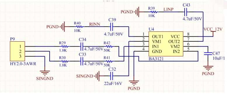
Ultimately, a chip from ROHM caught my attention—BA3121, an operational amplifier with ground potential movement capability.
I won't delve into the specifics of the chip's performance since you can download the datasheet for detailed information.
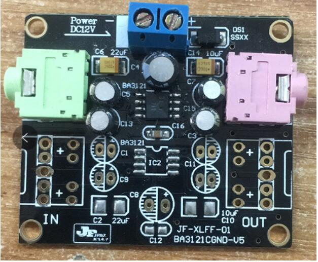
After constructing the actual circuit, it has been confirmed that this module effectively suppresses ground signal interference caused by ground loops. Please note that this module is active. Now, let's proceed with the actual circuit design.
I utilized the PAM8610 audio chip, which is an audio solution. The final actual wiring is as follows:

In the end, after prototyping the circuit board and conducting soldering tests, it was confirmed that this solution effectively resolves the "ding..." noise caused by audio ground loops, achieving results comparable to those obtained using a signal isolator.


