Design of USB DAC with Headphone Amplifier based on PCM2912A+TPA152
The PCM2912A, produced by TI, is a representative audio codec with a USB interface, mono microphone input, and stereo headphone output. It is particularly suitable for beginners as a sound card chip.
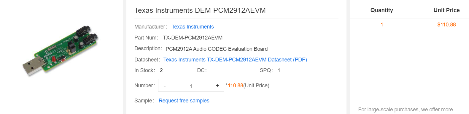
TI once created an evaluation module for this chip, with the model DEM-PCM2912AEVM. However, its price of 110 dollars does seem a bit steep, and without a headphone amplifier, it may not be very friendly to many high-quality headphones. So, let me introduce the DIY method for it.
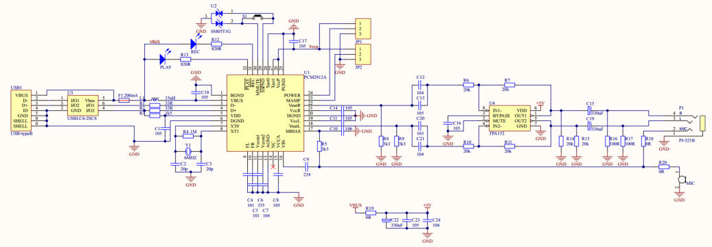
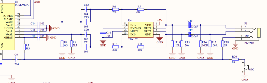
Overall Schematic Diagram
The USB sound card adopts the classic PCM2912A(https://www.unikeyic.com/products/13710010122586/DEM-PCM2912AEVM.html)+TPA152 solution, with all circuits designed following the recommended circuit designs in the chip manuals.
Detailed Design
• Interface Section:
The USB section is designed with ESD protection and fuse measures to ensure that the circuit is not easily damaged by static electricity during plugging and unplugging. The power input adopts a simple LC filter design to ensure clean input power and improve sound quality.
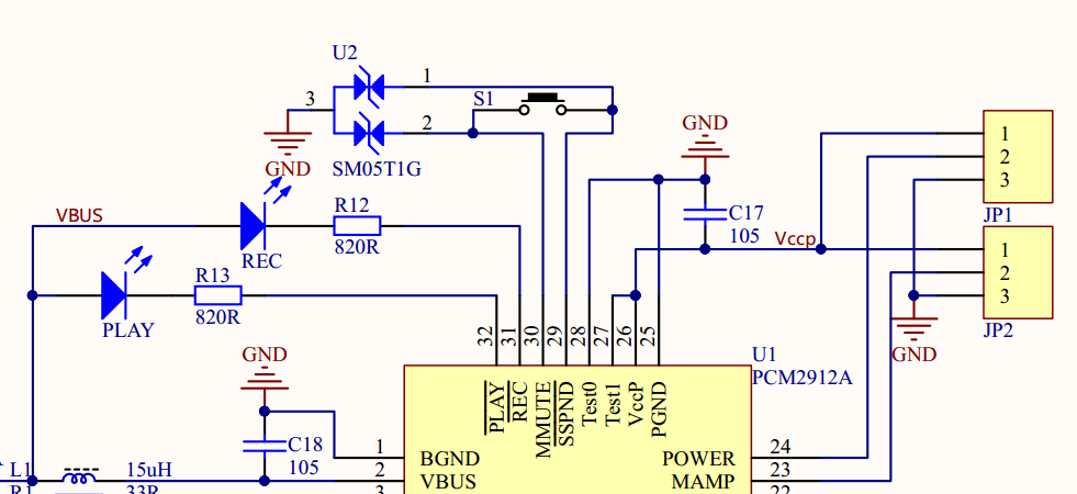
• Crystal Selection:
The crystal selected is the NDK NX8045GB-6MHZ-STD-CSF-3, in an 8mm x 4.5mm package, with a frequency of 6MHz and a temperature drift of 30ppm.

Microphone and Button Section: The function of the mute button for the microphone is not commonly used, so for reliability considerations, an SM05T1G is added as ESD protection. Additionally, two tin-jump wires are designed to select power-saving mode and microphone gain settings. The reason for using tin-jump wires is because I personally feel that these settings are not frequently adjusted, so there is no need to use complex jumper caps or dip switches.
• Power Amplifier Output and Headphone Interface:
The power amplifier section uses the standard TPA152(https://www.unikeyic.com/search?keyword=TPA152) circuit design, with output capacitors being two tantalum electrolytic capacitors, ensuring that the high-frequency equivalent series resistance (ESR) is not too high.
The output interface combines the microphone and headphone into one, aiming to be compatible with most mobile phone control headphones on the market. This allows for direct connection of a mobile phone headset, which is more practical than having separate interfaces, right?
Of course, a microphone output solution for single-headphone use has also been considered. A microphone position is reserved on the board for soldering a microphone to achieve microphone functionality.
• Bill of Materials
The components used are all relatively common and practical.
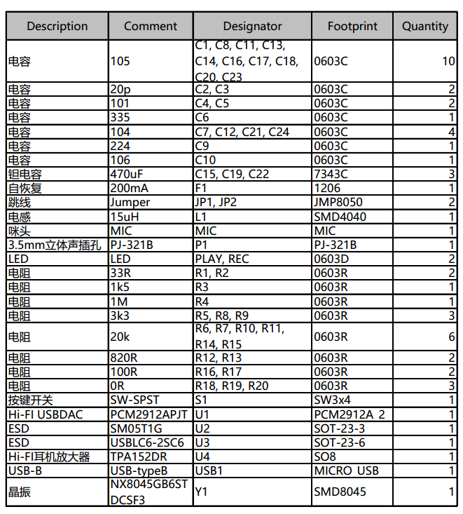
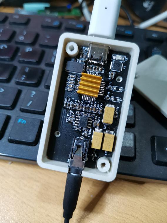
Photo of the Physical Prototype
First Version: Bare PCB
The main chip generates a little heat during operation

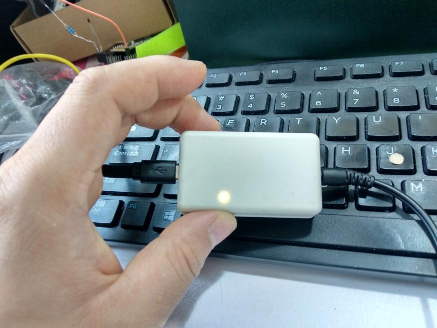
The appearance after adding the casing: MicroUSB Version

The appearance after adding the casing: Type-C Version
Appearance: