Arduino Hands-on - MAX30102 Wrist Heart Rate
I have prepared a series of experiments to try out different sensor and actuator modules, based on the principle that true knowledge comes from hands-on practice. The purpose of these experiments is to learn and exchange ideas. Regardless of whether they are successful (the program runs smoothly) or not, I will record the progress or challenges encountered – hoping to contribute and inspire.
【Arduino】168 Sensor Module Series Experiments (Data Code + Simulation Programming + Graphical Programming)
Experiment: MAX30102 Pulse Oximeter Wrist Heart Rate Pulse Detection Sensor Module.
MAX30102 is a comprehensive pulse oximetry and heart rate monitoring module. It includes internal LEDs, photodetectors, optical components, and low-noise electronic devices with ambient light suppression capability. MAX30102 provides a complete system solution, simplifying the design process for mobile and wearable devices. Operating on a single 1.8V power supply, MAX30102 provides a separate 5.0V power supply for the internal LEDs. Communication is achieved through a standard I2C compatible interface. The module can be software-configured to minimize standby current, allowing the power rails to remain energized at all times.
Applications:
Wearable devices
Fitness assistance devices

Advantages and Features of MAX30102:
- Heart rate monitor and pulse oximeter sensor input LED reflection solution
- Miniature 5.6mm x 3.3mm x 1.55mm 14-pin optical module
- Integrated cover glass for optimal and robust performance
- Ultra-low power operation for mobile devices
- Programmable sampling rate and LED current saving
- Low-power heart rate monitor (<1mW)
- Ultra-low standby current (0.7μA, typical)
- Fast data output capabilities
- High sampling rate
- Powerful motion artifact recovery capability
- High signal-to-noise ratio
- Operating temperature range of -40°C to +85°C
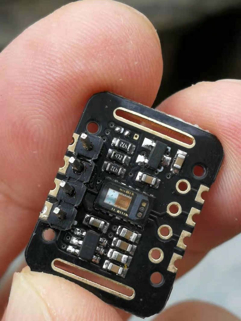
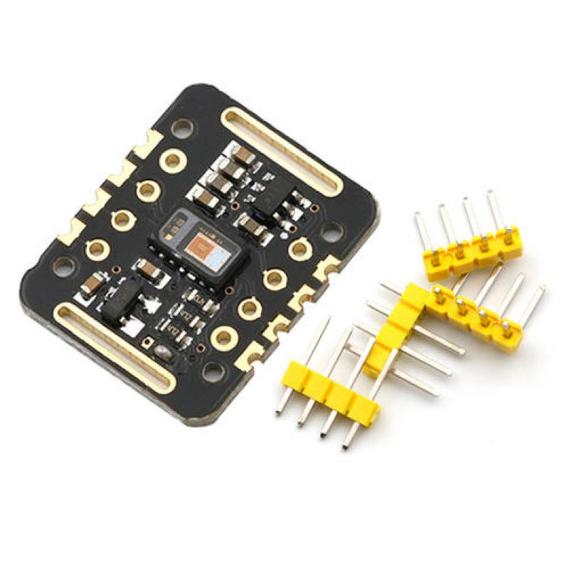
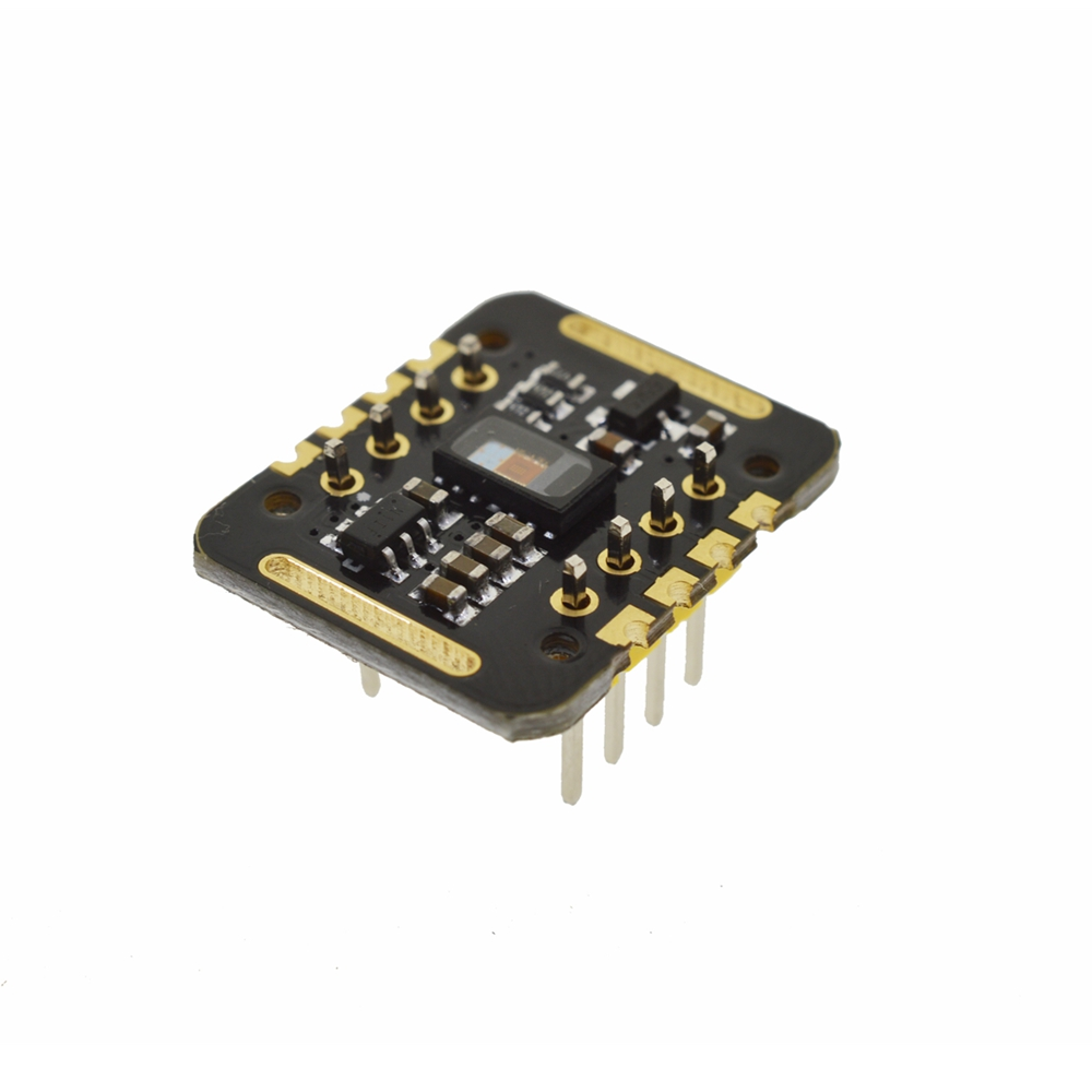
MAX30102 Wrist Heart Rate Module
It consists of two light-emitting DIODES, one photodetector, optimized optics, and low-noise analog signal processing to detect pulse oxygen saturation and heart rate signals.
1.By simply placing a finger on the sensor, it is possible to estimate the pulse oxygen saturation (SpO2) and pulse rate (equivalent to heartbeat).
2.Red blood cells carrying oxygen absorb more infrared light (850-1000nm), while red blood cells without oxygen absorb more red light (600-750nm).
3.Therefore, a pulse oximeter is like a mini spectrometer that analyzes oxygen saturation based on the absorption spectra of different types of red blood cells.
4.This real-time and fast measurement method is widely used in many clinical applications.
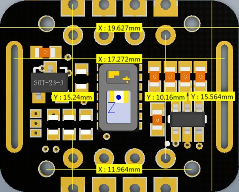
Schematic Diagram of MAX30102 Wrist Heart Rate Module

After extensive research and exploration, I have discovered a validated practical blood oxygen calibration formula from a program dedicated to studying the MAX30102 algorithm:
![]()
The value of R can be calculated by taking the logarithm of the intensity of red light and infrared light. This calibration expression is actually a quadratic curve fitting for blood oxygen saturation, obtained through measurements. Finally, the data on blood oxygen saturation can be outputted.
The MAX30102 wrist heart rate module is primarily used in the following applications:
Fitness devices
Smartphones
Tablets
Wearable devices

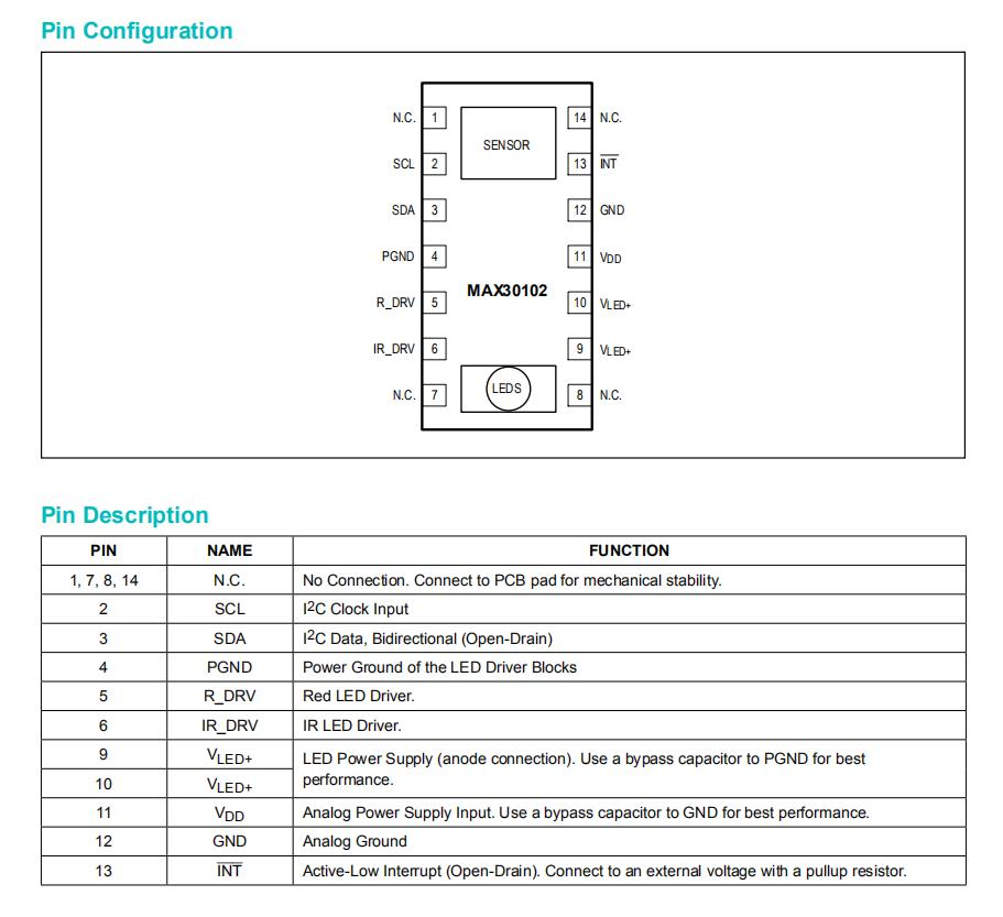
The light-emitting part of the MAX30102 includes two LEDs: one is a red LED (660nm) and the other is an infrared LED (880nm). This is the most common configuration for measuring blood oxygen saturation (SPO2). The receiving part consists of a photodiode that is sensitive to both visible and infrared light. The intensity of the received light is converted into a current signal, which is then sampled and converted by the built-in 18-bit ADC after passing through an ambient light elimination circuit. After the ADC conversion, the digital data is stored in a data register and can be read by an external MCU via the I2C bus. In terms of hardware, the power supply for the LEDs is separate from the power supply for other components. This is because the LEDs require a large instantaneous current (up to 50mA) to ensure sufficient light emission, which in turn requires a forward voltage of at least 3.1V. On the other hand, the remaining AD conversion and I2C bus sections need to operate at a lower voltage (1.8V) to meet the low-power requirements. Therefore, the sensor requires independent power supplies for these two parts. Additionally, since the LED power supply can generate a large instantaneous current, a large capacitor should be added near the power supply pin to mitigate the impact on the power voltage.
There are three main traditional methods for pulse measurement: extracting from the electrocardiogram signal, calculating pulse rate from the fluctuations measured by a pressure sensor during blood pressure measurement, and using the photoplethysmography method. The first two methods of signal extraction impose limitations on the patient's activities, and prolonged use may cause physical and psychological discomfort. In contrast, the photoplethysmography method is one of the most common methods for monitoring pulse measurement due to its simplicity, convenience, and high reliability.
The basic principle of photoplethysmography is to measure pulse and blood oxygen saturation by detecting variations in light transmittance caused by pulsation of the blood vessels in the human body. The sensor used in this method consists of a light source and a photodetector, which are typically attached to the patient's finger, wrist, or earlobe using a strap or clip. The light source usually consists of specific wavelength LEDs that selectively emit light near 660nm (red light) and 900nm (infrared light), targeting oxyhemoglobin (HbO2) and deoxyhemoglobin (Hb) in arterial blood. When the light beam passes through the peripheral blood vessels of the human body, the transmittance of this beam changes due to changes in blood volume caused by arterial pulsation. At this point, the reflected light from the human tissue is received by the photodetector, converted into an electric signal, amplified, and outputted. Since the pulse is a periodic signal that varies with the heartbeat, and arterial blood volume also exhibits periodic changes, the period of variation in the electric signal from the photodetector corresponds to the pulse rate.
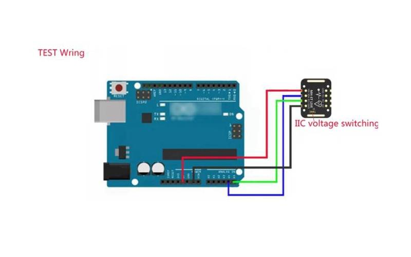
Schematic diagram of the MAX30102 wrist heart rate module experimental wiring.
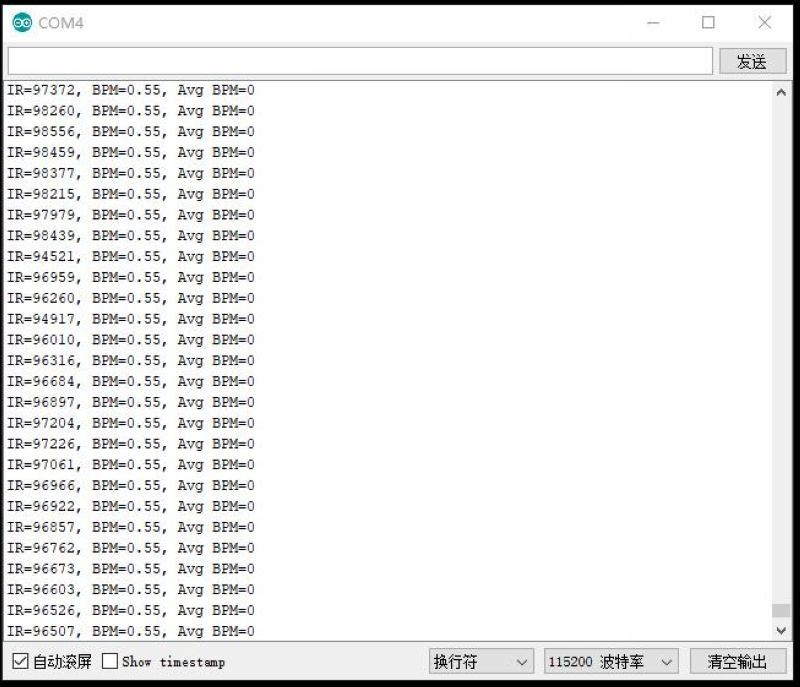
Open source code for experimentation.

Initializing…
Place your index finger on the sensor with steady pressure.
Module Electrical Schematic Number 2