Arduino Hands-on — 0.96-inch OLED Display
Experiment: 0.96 inch I2C IIC Communication 128*64 Display OLED LCD Screen Module
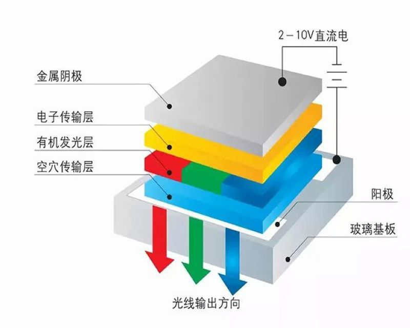
OLED, short for Organic Light-Emitting Diode, is also known as Organic Electroluminescence Display. It belongs to a kind of current-driven organic light-emitting device, in which light emission is achieved through the injection and recombination of charge carriers, with the intensity of light emission directly proportional to the injected current. Under the influence of an electric field, holes generated at the anode and electrons produced at the cathode move towards the hole transport layer and electron transport layer respectively, to finally reach the light-emitting layer. Upon meeting in the light-emitting layer, they form excitons that excite light-emitting molecules to emit visible light. Generally speaking, OLED can be divided into two categories based on the emissive materials: small molecule OLED and polymer OLED (also known as PLED). OLED is a device that utilizes multi-layer organic thin films to achieve electroluminescence, making it easy to fabricate with low driving voltages. These characteristics make OLED particularly outstanding for flat panel display applications. OLED displays are thinner and lighter compared to LCDs, with higher brightness, lower power consumption, faster response time, superior clarity, good flexibility, high luminous efficiency, meeting consumers' new demands for display technology. With more and more display manufacturers worldwide investing in research and development, the industrialization process of OLED has been significantly accelerated.
Characteristics of OLED
(1) Low power consumption - Compared to LCDs, OLEDs do not require a backlight source, which is a relatively energy-consuming part in LCDs, making OLEDs more energy-efficient. For example, a 24-inch AMOLED module consumes only 440mW, while a 24-inch polysilicon LCD module reaches 605mW.
(2) Fast response time - OLED technology has a fast response time compared to other technologies, with response times reaching the microsecond level. The higher response speed better achieves motion images. According to relevant data analysis, its response speed is approximately 1000 times faster than that of liquid crystal displays.
(3) Wide viewing angles - Compared to other displays, OLED screens do not exhibit distortion over a large viewing angle range due to their active light emission. The vertical and horizontal viewing angles exceed 170 degrees.
(4) High-resolution display capability - Most high-resolution OLED displays use active matrix organic light-emitting diode (AMOLED) technology, which can absorb up to 260,000 true colors of high resolution. With the advancement of science and technology, OLED resolutions are expected to increase further in the future.
(5) Wide temperature characteristics - Unlike LCDs, OLEDs can operate over a wide temperature range. According to technical analysis, OLEDs can function normally within a temperature range of -40 degrees Celsius to 80 degrees Celsius. This reduces geographical limitations, allowing for normal use even in extremely cold regions.
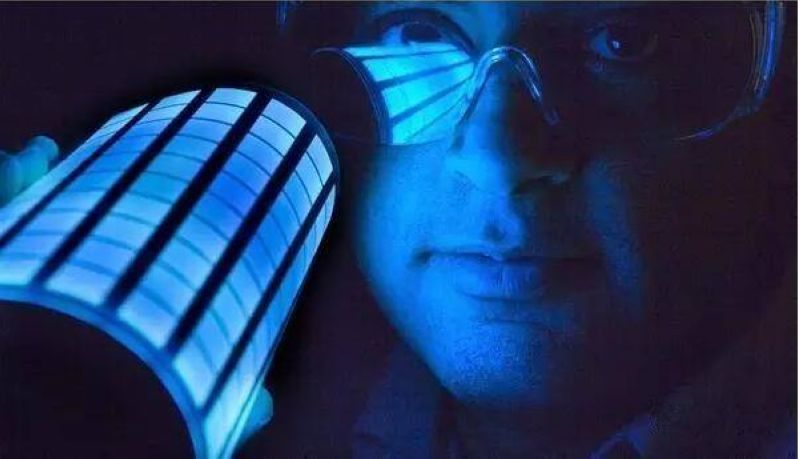
(6) OLED enables flexible screens - OLED technology can be produced on various flexible substrate materials such as plastic and resin. By depositing or coating organic layers on flexible substrates, OLEDs can achieve flexible screens.
(7) Lighter weight of OLED finished products - Compared to other products, OLEDs have a smaller footprint and thickness than LCDs. They have a higher resistance coefficient, able to withstand greater accelerations, vibrations, and harsh environments.
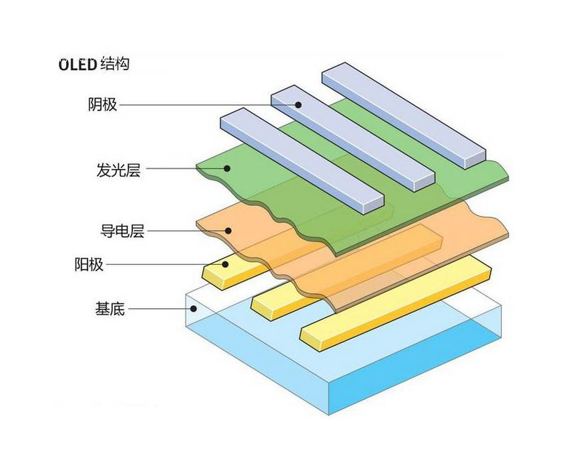
OLED Structure
The structure of an OLED consists of various components including the substrate, cathode, anode, hole injection layer (HIL), electron injection layer (EIL), hole transport layer (HTL), electron transport layer (ETL), electron blocking layer (EBL), hole blocking layer (HBL), and emissive layer (EML). The substrate serves as the foundation of the entire device, with all functional layers needing to be deposited onto it; typically, glass is used as the substrate material for the device, but if flexible OLED devices are required, other materials such as plastic may be used. The anode is connected to the positive terminal of the external driving voltage applied to the device, where the holes within the anode move towards the emissive layer within the device under the influence of the driving voltage. The anode needs to have a certain degree of transparency when the device is in operation, allowing light emitted from within the device to be observed externally; the most commonly used material for the anode is ITO. The hole injection layer modifies the anode of the device and facilitates the smooth injection of holes from the anode into the hole transport layer; the hole transport layer is responsible for transporting holes to the emissive layer. The electron blocking layer prevents electrons from the cathode from entering the emissive layer interface of the device, increasing the concentration of electrons at the emissive layer interface. The emissive layer is where the recombination of electrons and holes occurs to form excitons which then emit light. The hole blocking layer blocks the holes from the anode at the interface of the emissive layer in order to enhance the probability of electron-hole recombination at the emissive layer interface, thereby increasing the device's luminous efficiency. The electron transport layer is responsible for transporting electrons from the cathode to the emissive layer of the device; the electron injection layer functions to modify the cathode and transfer electrons to the electron transport layer. Electrons within the cathode move towards the device's emissive layer under the driving force of the external driving voltage, where they recombine with holes from the anode at the emissive layer.
Principle of Luminescence
The luminescent process of OLED devices can be divided into: injection of electrons and holes, transmission of electrons and holes, recombination of electrons and holes, and exciton excitation light emission. Specifically:
(1) Injection of electrons and holes. Electrons in the cathode and holes in the anode will move towards the light-emitting layer of the device under the driving voltage. In the process of moving towards the light-emitting layer, if the device contains an electron injection layer and a hole injection layer, electrons and holes first need to overcome the energy barrier between the cathode and the electron injection layer, as well as between the anode and the hole injection layer, and then move through the electron injection layer and hole injection layer to the electron transport layer and hole transport layer of the device; the electron injection layer and hole injection layer can increase the efficiency and lifespan of the device. The mechanism of electron injection in OLED devices is still under continuous research, and currently, the most commonly used mechanisms are tunneling effect and interface dipole mechanism.
(2) Transmission of electrons and holes. Under the driving voltage, electrons from the cathode and holes from the anode will respectively move to the electron transport layer and hole transport layer of the device. The electron transport layer and hole transport layer will then move electrons and holes to the interface of the light-emitting layer of the device; at the same time, the electron transport layer and hole transport layer will block the holes from the anode and electrons from the cathode at the interface of the light-emitting layer, allowing electrons and holes to accumulate at the interface of the light-emitting layer.
(3) Recombination of electrons and holes. When a certain number of electrons and holes at the interface of the light-emitting layer of the device are reached, electrons and holes will recombine to form excitons in the light-emitting layer.
(4) Light emission due to exciton de-excitation. Excitons generated in the light-emitting layer will activate the organic molecules in the light-emitting layer of the device, causing the outermost electrons of the organic molecules to transition from the ground state to the excited state. Since the electrons in the excited state are highly unstable, they will transition back to the ground state, releasing energy in the form of light during the transition, thereby achieving device illumination.
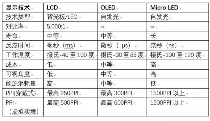
Comparison betweenOLEDand LED/LCD
1. Compared to the crystal layer of LED or LCD, the organic plastic layer of OLED is thinner, lighter, and more flexible.
2. The light-emitting layer of OLED is relatively light, allowing for the use of flexible materials in its base layer, rather than rigid materials. While OLED's base layer is made of plastic, LED and LCD use glass substrates.
3. OLED is brighter than LED. The organic layer of OLED is much thinner than the corresponding inorganic crystal layer in LED, allowing OLED's conductive and emitting layers to be multi-layered. Additionally, LED and LCD require glass as support, which absorbs some light. OLED, on the other hand, does not need to use glass.
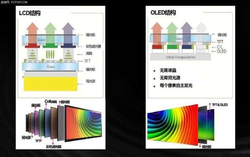
4. OLED does not require a backlight system like LCD. LCD selectively blocks certain backlight areas to display images, while OLED emits light by itself. Due to not needing a backlight system, OLED consumes less power compared to LCD (where most of the power consumption is for the backlight system). This is particularly important for battery-powered devices such as mobile phones.
5. OLED is easier to manufacture and can be made in larger sizes. Being made of plastic material, OLED can be manufactured into large thin sheets. In contrast, it would be much more challenging to use so many crystals and lay them flat.
6. OLED has a wide viewing angle, reaching around 170 degrees. LCD needs to block light when operating, leading to natural viewing obstacles at certain angles. As OLED emits light by itself, the viewing range is also much wider.
0.96 inch I2C IIC Communication 12864 Display OLED LCD Screen Module
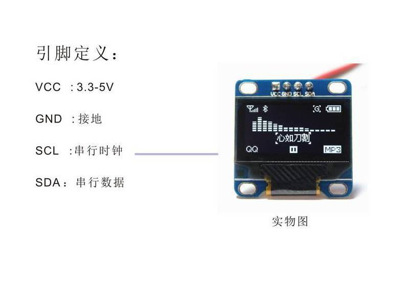
- l Voltage: 3V~5V DC
- l Operating Temperature: -30℃~70℃
- l Duty Duty: 1/64 duty
- l High Resolution: 128 64
- l Panel Size: 26.70 19.26 1.85 mm / 1.03 0.76 0.07 inches (approx.)
- l Effective Area: 21.74 11.2 mm / 0.86 0.44 inches (approx.)
- l Driver IC: SSD1306
- l 128 * 64 LED display module, supporting various control chips.
- l Fully compatible with 51 series, MSP430 series, STM32/2, CSR IC, etc.
- l Ultra-low power consumption: 0.08W when the full screen is lit.
- l Super high brightness and adjustable contrast
- l With embedded driver/controller
- l Interface Type: IIC
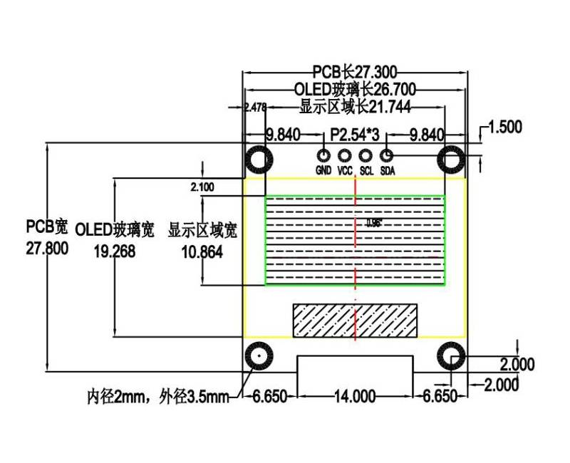
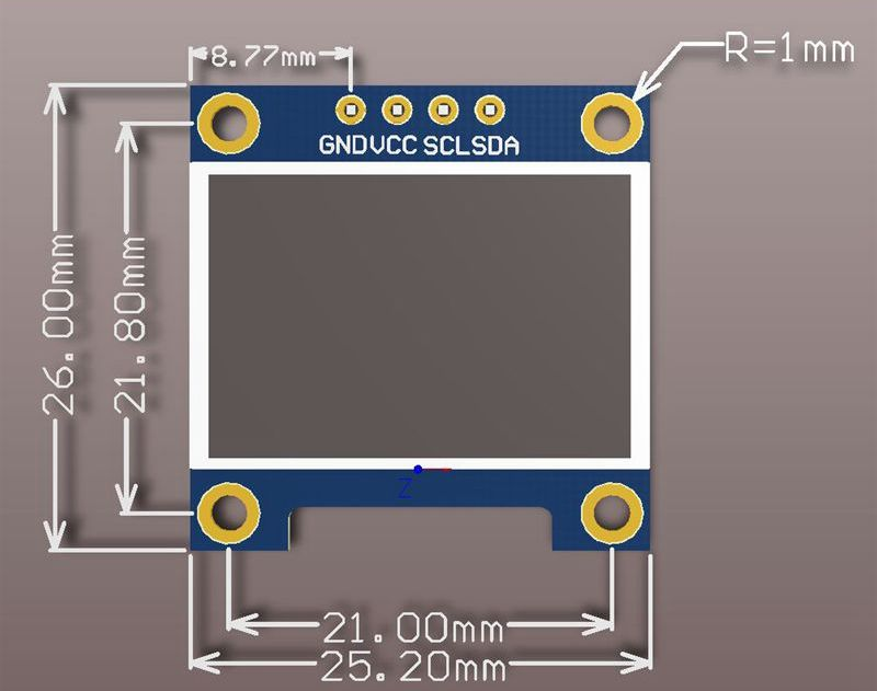

Schematic diagram of the module

Diagram of experimental wiring

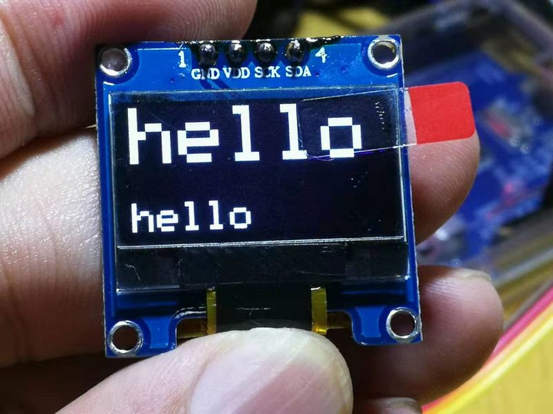
Experimental setup diagram
Two very important points about OLED:
Firstly, the pixel matrix. A pixel matrix, also known as a raster image or pixel map, is simply a graphic composed of the smallest units called pixels, and distortion may occur when scaled. The smallest unit forming a bitmap is a pixel, and a bitmap achieves its display effect through the arrangement of an array of pixels. Each pixel has its own color information. When editing a bitmap image, the objects that can be manipulated are each pixel. We can change the hue, saturation, and brightness of the image, thus altering the display effect of the image. To illustrate, a bitmap image is like a painting on a huge sandbox. When viewed from a distance, the image appears intricate and colorful. However, as you get extremely close, you can see each grain of sand that makes up the picture, with each grain having a simple, unchangeable color.
OLED is essentially an M x n pixel matrix, where specific pixel positions need to be illuminated in order to display content. For each pixel, it can either be lit up as 1 or not lit up as 0.
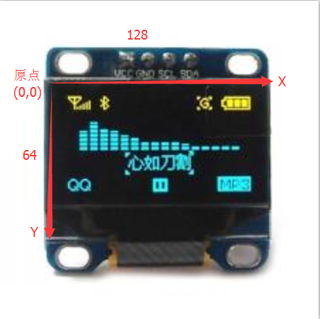
The Second: Coordinate System
A coordinate system is a commonly used auxiliary method in the field of science. Common types include the Cartesian coordinate system and the plane rectangular coordinate system. In order to describe the position of a particle, the speed and direction of its movement, a coordinate system must be chosen. In a frame of reference, a set of ordered data selected according to a specified method to determine the position of a point in space is called "coordinates." The method of determining coordinates in a particular problem is referred to as the coordinate system used for that problem. There are many types of coordinate systems, with commonly used ones including the Cartesian coordinate system, the plane polar coordinate system, the cylindrical coordinate system (also known as the cylindrical coordinate system), and the spherical coordinate system (also known as the spherical coordinate system). In high school physics, the commonly used coordinate system is the rectangular coordinate system or orthogonal coordinate system. In a broader sense, all abstract concepts of things exist with respect to the coordinate system to which they belong. The same object will have different abstract concepts represented in different coordinate systems. The number of abstract concepts related to the object expressed by the coordinate system, that is, the number of coordinate axes, is the dimension of the space in which the object exists. Two objects that can change each other must be in the same coordinate system.
In the OLED coordinate system, the top left corner is the origin, the X-axis extends to the right, and the Y-axis extends downwards.