
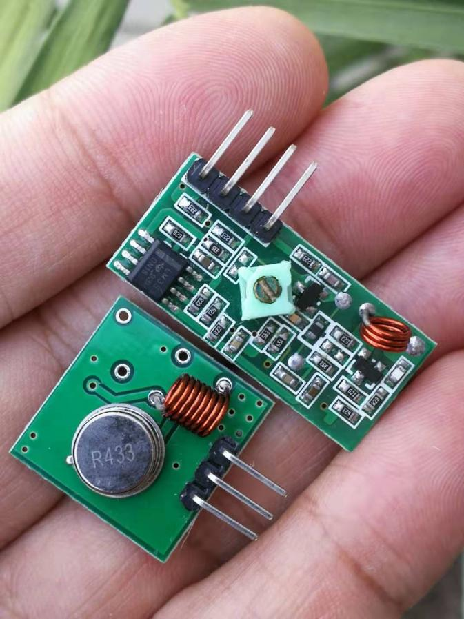
Arduino Hands-on - 433MHz Wireless Transmitter and Receiver Module
Experiment: 433M Wireless Transmitting and Receiving Module, Super Regenerative Anti-Theft Wireless Alarm Module.
Regenerative receivers, utilizing the principle of positive feedback, amplify the received signal and feed it back to the input for further amplification in a loop without frequency conversion. This design offers advantages such as simple circuitry, high sensitivity, compact size, and low cost. However, regenerative receivers may suffer from drawbacks including unstable sensitivity, poor selectivity, and low resistance to interference. Unlike superheterodyne technology where signals undergo frequency conversion, regenerative receivers process the signal directly.
Compared to superheterodyne technology, regenerative receivers have several advantages:
lSimple circuitry, with the most basic receiver requiring only one transistor to perform functions such as amplification, detection, and power amplification.
lHigh sensitivity.
lCompact size and low cost.
The main disadvantages of regenerative receivers are:
lUnstable sensitivity across the full frequency spectrum, making them more suitable for fixed-frequency applications.
lPoor selectivity and interference rejection capabilities.
lPoor frequency stability, leading to frequency drift.
lSusceptibility to blocking when receiving signals at close range.
433MHz wireless module
The 433MHz wireless module, utilizing high-frequency RF technology, is also known as the RF433 RF small module. It consists of a single IC RF front-end produced by an all-digital technology and an ATMEL AVR microcontroller, capable of high-speed transmission of data signals as a miniature transceiver, packaging, error checking, and error correction for wireless data transmission. The components are all industrial-grade standard, ensuring stable and reliable operation, with a compact size for easy installation. Widely used in various fields such as security alarms, wireless automatic meter reading, home and industrial automation, remote control, wireless data transmission, and more.
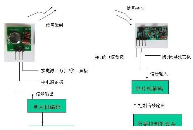
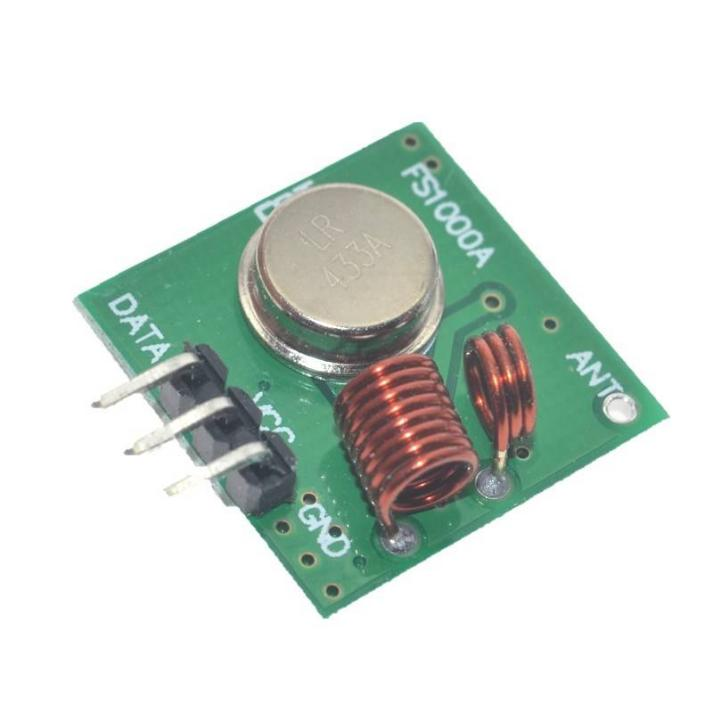
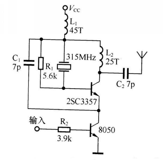
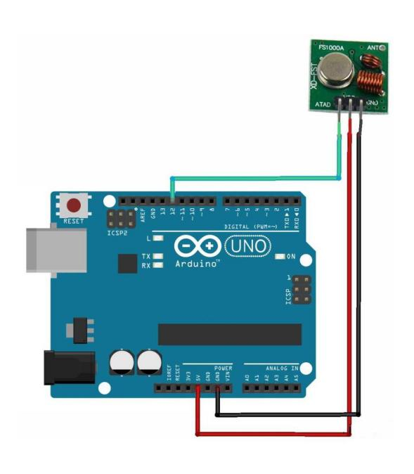
Transmitter module
lCommunication method: Amplitude Modulation (AM)
lOperating frequency: 315MHz/433MHz
lFrequency stability: ±75kHz
lTransmitting power: ≤500mW
lStatic current: ≤0.1μA
lTransmitting current: 3-50mA
lOperating voltage: DC 3-12V
lTransmitter head (utilizing 2SC3357 transistor)
Especially suitable for multi-transmit and single-receive wireless remote control and data transmission systems. The frequency stability of the SAW resonator is second only to that of crystals, while the frequency stability and consistency of common LC oscillators are poorer. Even with high-quality variable capacitors, it is difficult to guarantee that the tuned frequency will not deviate due to temperature changes and vibrations. The transmitter module does not have an integrated encoding circuit but includes a data modulation transistor Q1, enabling easy interfacing with other fixed encoding circuits, rolling code circuits, and microcontrollers without considering the working voltage of the encoding circuit and the magnitude of the output signal amplitude values. For example, when connected with encoding integrated circuits like PT2262 or SM5262, simply connect the data output pin (Pin 17) directly to the input terminal of the data module.
The transmission module has a wide operating voltage range of 3 to 12V. When the voltage changes, the transmission frequency remains basically unchanged. The receiving module paired with the transmission module can stably receive without any adjustments. When the transmission voltage is 3V, the open transmission distance is approximately 20 to 50 meters, with low transmission power. At 5V, the distance extends to about 100 to 200 meters, and at 9V, it reaches around 300 to 500 meters. The optimal operating voltage is 12V, which provides excellent transmission performance. The transmission current is approximately 60 milliamperes, and in clear conditions, the transmission distance ranges from 700 to 800 meters with a transmission power of about 500 milliwatts. Beyond 12V, power consumption increases, and the effective transmission power no longer significantly improves.
The main features of this module are its relatively high transmission power and long transmission distance, making it suitable for communication in harsh conditions. It is advisable to use a 25-centimeter long wire as the antenna. For long-distance transmission, it is recommended to set the antenna upright, as wireless radio signal transmission is influenced by various factors. Hence, the practical transmission distance is usually only half or even less than the nominal distance, which should be taken into consideration during development.
The data module adopts ASK modulation to reduce power consumption. When the data signal stops, the transmission current drops to zero. The data signal should be connected to the input terminal of the transmission module using resistors or direct connections and not capacitive coupling; otherwise, the transmission module will not function correctly. The data voltage level should be close to the actual operating voltage of the data module to achieve better modulation effects.
Ideally, the transmission module should be vertically installed on the edge of the motherboard, at least 5mm away from surrounding components to avoid impedance effects. The transmission distance of the module is related to the modulation signal frequency and amplitude, transmission voltage and battery capacity, transmission antenna, receiver sensitivity, and the transmitting environment. In an open area, the maximum transmission distance is around 800 meters, but obstacles may shorten this distance. Refraction and reflection during the wireless radio signal transmission process create dead zones and unstable areas, leading to varying transmission distances depending on the environmental conditions.
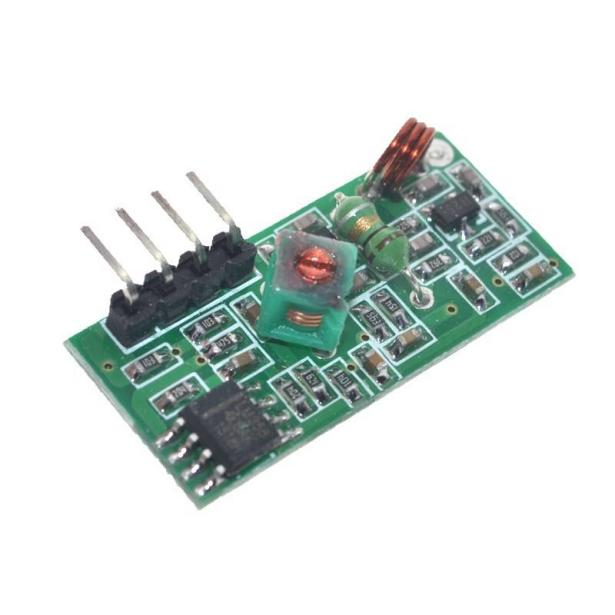
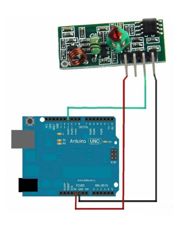
Super-regenerative Receiver Module
Dimensions: 30x13x8 millimeters
Main Technical Specifications:
lCommunication Method: Amplitude Modulation (AM)
lOperating Frequency: 315MHz/433MHz
lFrequency Stability: ±200kHz
lReceiver Sensitivity: -106dBm
lStatic Current: ≤5mA
lOperating Current: ≤5mA
lOperating Voltage: DC 5V
lOutput Method: TTL Level
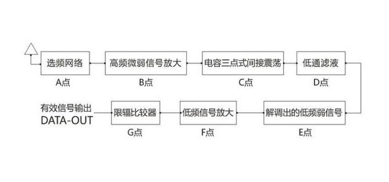
The working voltage of the receiver module is 5 volts, with a static current of 4 milliamperes. It operates as a super-regenerative receiving circuit, with a receiver sensitivity of -105dBm. The recommended antenna for reception is a wire measuring 25 to 30 centimeters in length, ideally positioned vertically. The receiver module itself does not come with a decoding integrated circuit, serving merely as a component. Its full potential is realized only when applied in specific circuits and further developed accordingly. This kind of design offers many advantages, as it can be flexibly adapted to work in conjunction with various decoding circuits or microcontrollers, providing convenience and flexibility in circuit design.
The advantages of this circuit include:
lThe antenna input end features a selective frequency circuit, independent of the quarter-wavelength antenna's selective function. When controlling over shorter distances, the external antenna can be shortened or even removed.
lThe waveform at the output end is clean without signals, with interference signals appearing as brief spike pulses rather than the dense noise waveforms produced by other super-regenerative receiving circuits, resulting in strong anti-interference capabilities.
lThe module itself emits minimal radiation, and combined with the shielding effect of the copper foil grounding mesh on the back of the circuit board, leakage from self-oscillation and intrusion of external interference signals are minimized.
lBy using a skeleton-core copper inductor to adjust the frequency to 315MHz before encapsulation, stability is greatly improved compared to circuits that use adjustable capacitors to adjust the receiving frequency. Adjustable capacitors have lower adjustment precision, offering only a range of 3/4 turns, whereas adjustable inductors allow for multi-turn adjustments. Adjusted capacitors cannot be sealed after adjustment, as variations in conductors or insulators will alter the capacitance and affect the receiving frequency. In contrast, unsealed adjustable capacitors can experience displacement between the fixed and moving plates under vibration, changes in distance due to thermal expansion and contraction, altered capacity due to humidity changes, and oxidation-induced capacity changes in the fixed and moving plates when operating in humid environments for extended periods. All these factors significantly impact frequency stability. Using adjustable inductors resolves these issues, as they can be sealed after adjustment, with the insulating sealant maintaining the inductance constant.
433M Wireless Transmitting and Receiving Module
The transmitting module can be freely paired with market-fixed code or learning code receiving modules of the same frequency, and can be matched with our store's wireless receiving modules. It features stable sound modulation, reliable performance, wide operating voltage range, good product consistency, and high cost-effectiveness. The super-regenerative receiving module adopts an LC oscillating circuit with built-in amplification and shaping, outputting data signals at TTL level that can be directly connected to a decoder, making it extremely convenient to use and available at a low price. The receiving module has a relatively wide receiving bandwidth, typically ±10MHz, with a factory default setting of 315MHz or 433.92MHz (frequency adjustment is possible within the range of 266MHz to 433MHz if special requirements arise).
Module Applications
Remote control switches, receiving modules, motorcycles, car anti-theft products, home security products, electric gates, roller shutters, windows, remote control sockets, remote-controlledLEDs, remote-controlled stereos, remote-controlled garage doors, remote-controlled sliding doors, remote-controlled rolling shutters, sliding gates, remote-controlled door opening systems, remote-controlled curtains, alarm hosts, alarms, remote-controlled motorcycles, remote-controlled electric vehicles, remote-controlled MP3 players, and more.
Usage Notes
lThe VCC voltage should be consistent with the module's operating voltage, and power filtering should be done effectively.
lThe antenna greatly affects the reception of the module. It is advisable to connect a 1/4 wavelength antenna, typically using a 50-ohm single-core wire, with the antenna length for 433M being approximately 17cm.
lThe position of the antenna also influences the module's reception. During installation, extend the antenna as straight as possible, away from shielding bodies, high-voltage areas, and sources of interference. When in use, the receiving frequency, decoding method, and oscillation resistance should match that of the transmitter.
lBoth the transmitting and receiving modules require external antennas; otherwise, the signal distance will only be a few centimeters.

Schematic diagram of the experimental setup
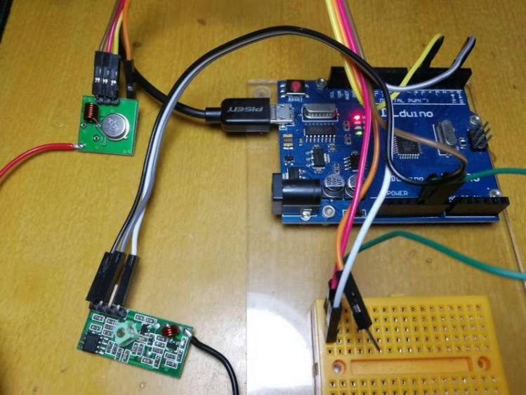
Experimental scene diagram


